EP2143941A1 - Direct drive generator and wind turbine - Google Patents
Direct drive generator and wind turbine Download PDFInfo
- Publication number
- EP2143941A1 EP2143941A1 EP08012250A EP08012250A EP2143941A1 EP 2143941 A1 EP2143941 A1 EP 2143941A1 EP 08012250 A EP08012250 A EP 08012250A EP 08012250 A EP08012250 A EP 08012250A EP 2143941 A1 EP2143941 A1 EP 2143941A1
- Authority
- EP
- European Patent Office
- Prior art keywords
- endplate
- arrangement
- stator
- direct drive
- rotor
- Prior art date
- Legal status (The legal status is an assumption and is not a legal conclusion. Google has not performed a legal analysis and makes no representation as to the accuracy of the status listed.)
- Granted
Links
Images


Classifications
-
- F—MECHANICAL ENGINEERING; LIGHTING; HEATING; WEAPONS; BLASTING
- F03—MACHINES OR ENGINES FOR LIQUIDS; WIND, SPRING, OR WEIGHT MOTORS; PRODUCING MECHANICAL POWER OR A REACTIVE PROPULSIVE THRUST, NOT OTHERWISE PROVIDED FOR
- F03D—WIND MOTORS
- F03D13/00—Assembly, mounting or commissioning of wind motors; Arrangements specially adapted for transporting wind motor components
- F03D13/20—Arrangements for mounting or supporting wind motors; Masts or towers for wind motors
-
- F—MECHANICAL ENGINEERING; LIGHTING; HEATING; WEAPONS; BLASTING
- F03—MACHINES OR ENGINES FOR LIQUIDS; WIND, SPRING, OR WEIGHT MOTORS; PRODUCING MECHANICAL POWER OR A REACTIVE PROPULSIVE THRUST, NOT OTHERWISE PROVIDED FOR
- F03D—WIND MOTORS
- F03D15/00—Transmission of mechanical power
- F03D15/20—Gearless transmission, i.e. direct-drive
-
- F—MECHANICAL ENGINEERING; LIGHTING; HEATING; WEAPONS; BLASTING
- F03—MACHINES OR ENGINES FOR LIQUIDS; WIND, SPRING, OR WEIGHT MOTORS; PRODUCING MECHANICAL POWER OR A REACTIVE PROPULSIVE THRUST, NOT OTHERWISE PROVIDED FOR
- F03D—WIND MOTORS
- F03D80/00—Details, components or accessories not provided for in groups F03D1/00 - F03D17/00
- F03D80/70—Bearing or lubricating arrangements
-
- F—MECHANICAL ENGINEERING; LIGHTING; HEATING; WEAPONS; BLASTING
- F03—MACHINES OR ENGINES FOR LIQUIDS; WIND, SPRING, OR WEIGHT MOTORS; PRODUCING MECHANICAL POWER OR A REACTIVE PROPULSIVE THRUST, NOT OTHERWISE PROVIDED FOR
- F03D—WIND MOTORS
- F03D9/00—Adaptations of wind motors for special use; Combinations of wind motors with apparatus driven thereby; Wind motors specially adapted for installation in particular locations
- F03D9/20—Wind motors characterised by the driven apparatus
- F03D9/25—Wind motors characterised by the driven apparatus the apparatus being an electrical generator
-
- H—ELECTRICITY
- H02—GENERATION; CONVERSION OR DISTRIBUTION OF ELECTRIC POWER
- H02K—DYNAMO-ELECTRIC MACHINES
- H02K1/00—Details of the magnetic circuit
- H02K1/06—Details of the magnetic circuit characterised by the shape, form or construction
- H02K1/12—Stationary parts of the magnetic circuit
- H02K1/18—Means for mounting or fastening magnetic stationary parts on to, or to, the stator structures
- H02K1/185—Means for mounting or fastening magnetic stationary parts on to, or to, the stator structures to outer stators
-
- H—ELECTRICITY
- H02—GENERATION; CONVERSION OR DISTRIBUTION OF ELECTRIC POWER
- H02K—DYNAMO-ELECTRIC MACHINES
- H02K1/00—Details of the magnetic circuit
- H02K1/06—Details of the magnetic circuit characterised by the shape, form or construction
- H02K1/12—Stationary parts of the magnetic circuit
- H02K1/18—Means for mounting or fastening magnetic stationary parts on to, or to, the stator structures
- H02K1/187—Means for mounting or fastening magnetic stationary parts on to, or to, the stator structures to inner stators
-
- H—ELECTRICITY
- H02—GENERATION; CONVERSION OR DISTRIBUTION OF ELECTRIC POWER
- H02K—DYNAMO-ELECTRIC MACHINES
- H02K1/00—Details of the magnetic circuit
- H02K1/06—Details of the magnetic circuit characterised by the shape, form or construction
- H02K1/22—Rotating parts of the magnetic circuit
- H02K1/28—Means for mounting or fastening rotating magnetic parts on to, or to, the rotor structures
- H02K1/30—Means for mounting or fastening rotating magnetic parts on to, or to, the rotor structures using intermediate parts, e.g. spiders
-
- H—ELECTRICITY
- H02—GENERATION; CONVERSION OR DISTRIBUTION OF ELECTRIC POWER
- H02K—DYNAMO-ELECTRIC MACHINES
- H02K7/00—Arrangements for handling mechanical energy structurally associated with dynamo-electric machines, e.g. structural association with mechanical driving motors or auxiliary dynamo-electric machines
- H02K7/18—Structural association of electric generators with mechanical driving motors, e.g. with turbines
- H02K7/1807—Rotary generators
- H02K7/1823—Rotary generators structurally associated with turbines or similar engines
- H02K7/183—Rotary generators structurally associated with turbines or similar engines wherein the turbine is a wind turbine
- H02K7/1838—Generators mounted in a nacelle or similar structure of a horizontal axis wind turbine
-
- H—ELECTRICITY
- H02—GENERATION; CONVERSION OR DISTRIBUTION OF ELECTRIC POWER
- H02K—DYNAMO-ELECTRIC MACHINES
- H02K7/00—Arrangements for handling mechanical energy structurally associated with dynamo-electric machines, e.g. structural association with mechanical driving motors or auxiliary dynamo-electric machines
- H02K7/18—Structural association of electric generators with mechanical driving motors, e.g. with turbines
- H02K7/1807—Rotary generators
- H02K7/1823—Rotary generators structurally associated with turbines or similar engines
- H02K7/183—Rotary generators structurally associated with turbines or similar engines wherein the turbine is a wind turbine
-
- Y—GENERAL TAGGING OF NEW TECHNOLOGICAL DEVELOPMENTS; GENERAL TAGGING OF CROSS-SECTIONAL TECHNOLOGIES SPANNING OVER SEVERAL SECTIONS OF THE IPC; TECHNICAL SUBJECTS COVERED BY FORMER USPC CROSS-REFERENCE ART COLLECTIONS [XRACs] AND DIGESTS
- Y02—TECHNOLOGIES OR APPLICATIONS FOR MITIGATION OR ADAPTATION AGAINST CLIMATE CHANGE
- Y02E—REDUCTION OF GREENHOUSE GAS [GHG] EMISSIONS, RELATED TO ENERGY GENERATION, TRANSMISSION OR DISTRIBUTION
- Y02E10/00—Energy generation through renewable energy sources
- Y02E10/70—Wind energy
- Y02E10/72—Wind turbines with rotation axis in wind direction
-
- Y—GENERAL TAGGING OF NEW TECHNOLOGICAL DEVELOPMENTS; GENERAL TAGGING OF CROSS-SECTIONAL TECHNOLOGIES SPANNING OVER SEVERAL SECTIONS OF THE IPC; TECHNICAL SUBJECTS COVERED BY FORMER USPC CROSS-REFERENCE ART COLLECTIONS [XRACs] AND DIGESTS
- Y02—TECHNOLOGIES OR APPLICATIONS FOR MITIGATION OR ADAPTATION AGAINST CLIMATE CHANGE
- Y02E—REDUCTION OF GREENHOUSE GAS [GHG] EMISSIONS, RELATED TO ENERGY GENERATION, TRANSMISSION OR DISTRIBUTION
- Y02E10/00—Energy generation through renewable energy sources
- Y02E10/70—Wind energy
- Y02E10/728—Onshore wind turbines
Definitions
- the invention relates to a direct drive generator for a wind turbine and a wind turbine comprising such a direct drive generator.
- the first type of a wind turbine is the more classical type of a wind turbine comprising a gearbox arranged between the main shaft and a generator of the wind turbine.
- the second type of a wind turbine is a gearless type comprising a direct drive or a directly driven generator.
- a direct drive generator can be made as a synchronous generator with winded rotor or with permanent magnets attached to the rotor, or it can be designed as an alternative type of a generator.
- the width of the air gap between the rotor and the stator of the generator is preferably maintained constantly or at least within certain tolerances during the operation of the wind turbine and the direct drive generator respectively even when the arrangement of wind turbine rotor, main shaft and direct drive generator is subject to loads.
- the drawback of such a design is that the one-side support of the stator makes it difficult to maintain the width of the air gap at least substantially constant at the unsupported side of the stator in particular when the entire generator structure is not only subject to gravity and mass inertia but also to unbalanced magnetic pull.
- a direct drive generator with such a two-bearing arrangement needs a large and heavy stator support structure capable of absorbing relatively large bending moments of the stator.
- Such a stator support structure is e.g. described in WO 02/05408 A1 wherein the stator support structure comprises a support construction having a plenty of support arms.
- the two-bearing arrangement is replaced with a single bearing with a stationary inner bearing part attached to a stationary inner shaft and a rotating outer bearing part supporting the rotor of the direct drive generator.
- Wind turbines comprising a direct drive generator with a single bearing are disclosed in US 2006/0152014 A1 and WO 02/057624 A1 . But the replacement of the two bearings with a single bearing does not substantially change the drawback of the unilaterally supported stator structure.
- the stationary inner shaft concept is replaced with a rotating shaft concept. Since the stator of the generator is supported on both sides according to the rotating shaft concept, it is easier to maintain the width of the air gap between the rotor and the stator of the generator at least substantially constantly.
- the rotating shaft concept There are two known variants of the rotating shaft concept, one with a two-bearing arrangement and one with a four-bearing arrangement.
- the bearings of the generator act as bearings of a main shaft for the wind turbine which main shaft is connected to the wind turbine rotor.
- the stator structure is supported towards the main shaft and attached to a bedplate of the wind turbine.
- Wind turbines having such a design are disclosed in US 7,119,453 B2 and WO 03/023943 A2 .
- a drawback of this design is that the stator structure needs to be dimensioned to absorb and transfer all wind turbine rotor loads, i.e. the weight of the wind turbine rotor and all asymmetric aerodynamic loads to maintain the width of the air gap within the necessary tolerances. On large wind turbines this leads to very heavy and expensive stator structures.
- the main shaft of the wind turbine which is connected to the wind turbine rotor on its one end is supported by its own two bearings and carries at its other end the direct drive generator.
- the direct drive generator has a two-bearing arrangement for the centring of the rotor inside the stator.
- An example of such a wind turbine is described in US 6,781,276 B1 .
- the generator stator is carried by the generator rotor and torque is transferred from the generator to the wind turbine bedplate through a torque arm arrangement.
- the torque arm arrangement needs to comprise some kind of flexibility, e.g. implemented with rubber elements, to allow for minor misalignments between the main shaft - generator structure and the turbine bedplate.
- the bilateral support of the stator on the rotor enables for a relatively lightweight stator structure.
- the main drawback of this design is that a total of four bearings are required, and that the full torque has at least partially to pass through these bearings. For large wind turbines this means comparatively large and expensive bearings. Furthermore, for large wind turbines the torque arm arrangement becomes a comparatively substantial and heavy structure.
- the wind turbine comprises a stationary shaft as well as a direct drive generator having an inner stator and an outer rotor.
- the inner stator is arranged on the stationary shaft.
- the outer rotor is connected to the hub of the wind turbine, on the front side connected to the stationary shaft by a front bearing and on the rear side connected to the stationary shaft by rear bearing.
- a wind turbine comprising a direct drive generator having a rotor and a stator
- the rotor of the direct drive generator is attached to the rear side of a main shaft which main shaft is supported by two main bearings.
- the stator is substantially arranged around the rotor and comprises a front endplate, a rear endplate and a casing element connecting the front and the rear endplate to each other.
- the rear endplate of the stator is supported on the rotor or the main shaft by a third bearing.
- the front endplate of the stator is at least indirectly attached to a stationary part of the wind turbine. Therefore in the not pre-published EP 07013519.9 a three bearing arrangement is described.
- Such a three bearing structure can be sometimes statically undetermined.
- any misalignments due to mounting tolerances or any deformations arising as a result of gravity or external loads to the main shaft and/or the direct drive generator could potentially lead to an uneven load distribution between the three bearings of the wind turbine which in turn could cause a premature bearing failure.
- the front endplate of the stator is therefore at least partially in a certain adequate extent flexible in the directions of a centre axis of the main shaft.
- the front endplate acts like a membrane supporting the stator substantially firmly in the radial direction so as to maintain the air gap, but flexing readily so as to enable e.g. a bending of the main shaft with no major resistance.
- a direct drive generator for a wind turbine comprising a stator arrangement and a rotor arrangement, wherein the stator arrangement and/or the rotor arrangement comprises at least one at least partly flexible front and/or rear endplate, wherein the at least one endplate is at least partly, preferably completely made of fibreglass.
- Fibreglass comprises a relatively low module of elasticity and is therefore an appropriate material for the at least one endplate in view of the required flexibility. Additionally fibreglass comprises excellent corrosion behaviour, even in an aggressive environment like an offshore application of a wind turbine.
- a further advantage of fibreglass as material for a generator is the well electrical isolation.
- a direct drive generator comprising at least one such an endplate made of fibreglass is therefore well suitably for a wind turbine comprising a drive configuration which could be sometimes statically undetermined, e.g. a drive configuration with a three bearing structure.
- the direct drive generator comprises a centre axis, wherein the at least one endplate is at least partially in a certain extent flexible in the directions of the centre axis.
- the at least one endplate flexing readily so as to enable e.g. a bending of a respective component of the drive configuration of the wind turbine with no major resistance so that there occurs substantially no uneven load distribution between e.g. the three bearings of the drive configuration of the wind turbine.
- the at least one endplate is a ring-shaped endplate.
- the at least one endplate has a thickness of approximately 15 - 50 mm, preferably 20 - 30 mm in the direction of the centre axis.
- the at least one endplate has such dimensions e.g. in dependence of the structure of the at least one endplate that the at least one endplate has a comparatively little bending stiffness.
- the stator arrangement is substantially arranged around the rotor arrangement, comprises a front endplate, a rear endplate and a hollow cylindrical stator element connecting the front endplate and the rear endplate with each other.
- the hollow cylindrical stator element comprises on the inside at least one lamination stack provided with at least one winding, typically with a plurality of windings.
- the rotor arrangement is substantially arranged inside the stator arrangement.
- the rotor arrangement comprises a front endplate, a rear endplate and a hollow cylindrical rotor element connecting the front endplate and the rear endplate with each other.
- the hollow cylindrical rotor element comprises on the outside at least one permanent magnet arranged oppositely to the lamination stack with windings for power generation.
- a plurality of permanent magnets are arranged on the outer surface of,the hollow cylindrical rotor element.
- the rotor arrangement is substantially arranged around the stator arrangement, comprises a front endplate, a rear endplate and a hollow cylindrical rotor element connecting the front endplate and the rear endplate with each other.
- the hollow cylindrical rotor element comprises at least one permanent magnet on the inside.
- a plurality of permanent magnets are arranged on the inner surface of the hollow cylindrical rotor element.
- the stator arrangement is substantially arranged inside the rotor arrangement and comprises a stator support structure.
- a stator support structure Preferably at least one lamination stack provided with at least one winding, typically with a plurality of windings, is arranged on the stator support structure oppositely to the permanent magnets for power generation.
- a wind turbine comprising a direct drive generator as previously disclosed and a drive configuration for turning the rotor arrangement relatively to the stator arrangement comprising at least three bearings or two bearings wherein at least one of the two bearings is a four-point bearing which typically shows the behaviour of two bearings so that the two bearing arrangement with at least one four-point bearing behaves like a three bearing structure.
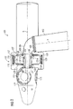
- FIG 1 shows schematically a first embodiment of a wind turbine 1 comprising a direct drive generator 2 which is arranged on the downwind side of a tower 3 of the wind turbine 1.
- a tower flange 4 is arranged on the top of the tower 3.
- a bedplate 5 is attached to the tower flange 4.
- the wind turbine 1 comprises in a not explicitly shown manner a yaw system for turning the bedplate 5 of the wind turbine around the axis Y together with the other components of the wind turbine 1 which are directly or indirectly attached to the bedplate 5.
- a bearing housing 6 is firmly arranged on the bedplate 5.
- the bearing housing 6 comprises two main bearings 7 and 8. Whilst each fixed part of the main bearings 7, 8 is attached to the bearing housing 6, each rotating part of the main bearings 7, 8 is attached to a main shaft 9. On the front end the main shaft 9 is connected to a hub 11 of the wind turbine 1.
- the hub 11 comprises three mounting devices 12 for three not shown, but well known wind turbine rotor blades.
- the main shaft 9 comprises a ring like flange 13 firmly connected to the main shaft 9.
- the bearing housing 6 comprises on the rear end a ring like flange 14.
- a tube like connection piece 15 with a first flange 16 on its front side and with a second flange 17 on its rear side is bolted with the ring like flange 14 of the bearing housing 6.
- the direct drive generator 2 is arranged on the main shaft 9 and on the bearing housing 6 and thus on the bedplate 5.
- the main shaft 9 and the direct drive generator 2 comprise a joint centre axis A.
- the direct drive generator 2 is one unit comprising a rotor arrangement 18 and a stator arrangement 19.
- the rotor arrangement 18 comprises on the front side a ring like flange 20.
- the ring like flange 20 is bolted with the ring like flange 13 of the main shaft 9.
- permanent magnets 24 are mounted on the outer surface of a ring element 23 of the rotor arrangement 18.
- On the rear side the rotor arrangement 18 comprises a lug 25.
- a tube like projection 26 is attached to the lug 25 by bolts.
- a third bearing 27 is arranged on the tube like projection 26.
- the stator arrangement 19 comprises a rear ring-shaped stator endplate 28 attached to the substantially stationary part or housing of the third bearing 27.
- stator arrangement 19 comprises a front ring-shaped stator endplate 29 having a ring like flange 30.
- the ring like flange 30 of the front endplate 29 and the ring like flange 17 of the tube like connection piece 15 are bolted together.
- a hollow cylindrical stator element 32 connects the front ring-shaped endplate 29 and the rear ring-shaped endplate 29 to each other.
- the hollow cylindrical stator element 32 comprises on the inside and the inner surface respectively a lamination stack 33 with windings.
- the lamination stack 33 with windings of the stator arrangement 19 and the permanent magnets 24 of the rotor arrangement 18 are arranged oppositely to each other with an intermediate ring-shaped air gap 34 of approximately 5 mm.
- the rotor arrangement 18 can turn together with the main shaft 9 relatively to the stator arrangement 19 around the centre axis A.
- stator arrangement 19 is supported on the rear side with the rear endplate 28 on the rotor arrangement 18 via the third bearing 27 and is supported on the front side with the front endplate 29 via the bearing housing 6 on the fixed structure of the wind turbine bedplate 5 close to the main bearing 8.
- the front endplate 29 of the stator arrangement 19 which is supported on the fixed structure of the bedplate 5 is made of fibreglass and thus comprises sufficient flexibility in the directions of the centre axis A.
- the front endplate 29 acts like a membrane supporting the stator arrangement 19 substantially firmly in the radial direction so as to maintain the width of the air gap 34 substantially constant, but flexing readily so as to allow e.g. a bending of the main shaft 9 with no major resistance.
- the front endplate 29 has thereby a thickness of approximately 15 - 50 mm, preferably 20 - 30 mm and has a comparatively little bending stiffness.
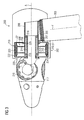
- FIG 2 shows schematically a second embodiment of a wind turbine 100 comprising a direct drive generator 102 which is arranged on the upwind side of a tower 103 of the wind turbine 100.
- a retaining arm 106 is on its base side directly arranged on a bedplate 105. On the other side the retaining arm 106 comprises a flange 108. A stationary shaft 107 is attached to the flange 108 with a flange 109.
- a main shaft 110 is supported towards the stationary shaft 107 by means of a first main bearing 111 and a second main bearing 112. On the front end the main shaft 110 is connected to a hub 114 of the wind turbine 100.
- the hub 114 comprises three mounting devices 115 for three not explicitly shown, but well known wind turbine rotor blades.
- the direct drive generator 102 is substantially arranged around the main shaft 110 and comprises a rotor arrangement 116 and a stator arrangement 117.
- the rotor arrangement 116 comprises a front ring-shaped rotor endplate 118, a rear ring-shaped rotor endplate 119 and a hollow cylindrical rotor element 120 connecting the front 118 and the rear 119 rotor endplate with each other.
- the hollow cylindrical rotor element 120 carries around its outer perimeter not in detail shown permanent magnets 125.
- the stator arrangement 117 comprises a front ring-shaped stator endplate 126, a rear ring-shaped stator endplate 127 and a hollow cylindrical stator element 128 connecting the front 126 and the rear 127 stator endplate with each other.
- the hollow cylindrical stator element 128 carries around its inner perimeter a not in detail shown lamination stack 133 with windings.
- the lamination stack 133 with windings and the permanent magnets 125 are arranged oppositely to each other for power generation with an intermediate ring-shaped air gap 134 of approximately 5 mm.
- the width of the air gap 134 is so small that the air gap 134 is not explicitly visible in FIG 2 .
- the wind turbine 100 in particular the direct drive generator 102 comprise a third or front generator bearing 135 and a fourth or rear generator bearing 136.
- the third bearing 135 is in case of the present embodiment of the invention attached to a flange 137 of the main shaft 110. More precisely the inner bearing shell of the third bearing 135 is firmly attached to the flange 137 of the main shaft 110. The inner bearing shell of the third bearing 135 is furthermore firmly attached to the front rotor endplate 118, which supports the front part of the rotor arrangement 116. The outer bearing shell of the third bearing 135 is firmly connected to the front stator endplate 126, which supports the front part of the stator arrangement 117.
- the rear part of the stator arrangement 117 is supported by the rear stator endplate 127, which is firmly connected to the flange 109 of the stationary shaft 107 and thus to the retaining arrangement.
- the inner bearing shell of the fourth bearing 136 is firmly attached to the rear stator endplate 127 and the rear rotor endplate 119 supporting the rear part of the rotor arrangement 116 is firmly connected to the outer bearing shell of the fourth bearing 136.
- the main shaft 110 turns in operation of the wind turbine 100 together with the rotor arrangement 116 relatively to the stator arrangement 117.
- the front rotor endplate 118 firmly supported on the main shaft 110 and the rear stator endplate 127 firmly supported on the retaining arrangement are made of fibreglass and thus comprise a certain and sufficient extent of flexibility in the directions of the centre axis A.
- the front rotor endplate 118 and the rear stator endplate 127 have thereby a thickness of approximately 15 - 50 mm, preferably 20 - 30 mm and a comparatively little bending stiffness.
- end plates 118, 127 act like membranes supporting the rotor arrangement 116 and the stator arrangement 117 substantially firmly in the radial direction so as to maintain the width of the air gap 134, but flexing readily so as to allow e.g. a bending of the main shaft 110 with no major resistance.
- the end plates 118, 127 simply flex passively when e.g. the main shaft 110 is shifted a bit by deflection.
- FIG 3 shows schematically a third embodiment of a wind turbine 200 comprising a direct drive generator 202 having a centre axis A which is arranged on the upwind side of a tower 203 of the wind turbine 200.
- the wind turbine 200 comprises a stationary outer shaft 206.
- the rear side of the stationary outer shaft 206 is attached to a retaining arrangement 207 which is attached to a bedplate 205.
- a stator arrangement 208 of the direct drive generator 202 is arranged on the front side of the stationary outer shaft 206 .
- the stator arrangement 208 comprises a stator support structure 209 and a lamination stack 210 with windings 211.
- the stator support structure 209 comprises two support elements 212 for a two side support of the lamination stack 210.
- the support elements 212 are ring-shaped support elements 212 attached, e.g. bolted, to the outside of the stationary outer shaft 206.
- the ring-shaped support elements 212 are able to be compact or are able to comprise spokes or a spoke structure.
- a kind of hollow cylindrical support element 213 is attached to the outer ends of the ring-shaped support elements 212.
- the hollow cylindrical support element 213 carries the ring-shaped lamination stack 210 with windings 211.
- the lamination stack 210 is able to comprise ring segment shaped lamination stack segments each having at least one winding 211 which segments build in their entirety the lamination stack 210.
- a rotatable inner shaft 214 is arranged inside the stationary outer shaft 206 and rotatably supported by two main bearings 215, 216 against the stationary outer shaft 206.
- the centre axis A is a joint centre axis A of the direct drive generator 202, the rotatable inner shaft 206 and the stationary outer shaft 214.
- a hub 217 is connected to the front end of the rotatable inner shaft 214 e.g. by means of bolts.
- the hub 217 comprises three mounting devices 218 for three not shown, but well known wind turbine rotor blades.
- the rotatable inner shaft 214 can turn together with the hub 217.
- a rotor arrangement 219 is substantially arranged around the stator arrangement 208.
- the rotor arrangement 219 comprises a front ring-shaped endplate 220, a rear ring-shaped endplate 221 and a hollow cylindrical rotor element 222 connecting the front ring-shaped endplate 220 and the rear ring-shaped endplate 221 to each other.
- On the inside the hollow cylindrical rotor element 222 comprises a plurality of permanent magnets 223 substantially arranged oppositely to the lamination stack 210.
- An air gap 224 having a width of approximately 5 mm is located between the permanent magnets 223 and the lamination stack 210.
- the front ring-shaped endplate 220 is connected e.g. bolted to the hub 217 and the rotatable inner shaft 214.
- the rear ring-shaped endplate 221 is connected to the stationary outer shaft 206 by means of a third bearing, a so called support bearing 225.
- the rotor arrangement 219 has a two side support.
- the rotor arrangement 219 can turn together with the hub 217 and the rotatable inner shaft 214, wherein in particular the permanent magnets 223 turn relatively to the lamination stack 210 for power generation.
- the front endplate 220 of the rotor arrangement 219 comprises an adequate flexibility in the directions of the centre axis A.
- the front endplate 220 acts like a membrane supporting the rotor arrangement 219 substantially firmly in the radial direction so as to maintain the width of the air gap 224, but flexing readily so as to allow e.g. a bending of the rotatable inner shaft 214 and the stationary outer shaft 206 with no major resistance.
- the front endplate 220 has such dimensions that it has a comparatively little bending stiffness. It simply flexes passively when e.g.
- the rotatable inner shaft 214 is shifted a bit by deflection.
- the front endplate 220 bends in the directions of the centre axis A wherein the width of the air gap 224 is maintained substantially constant or within required tolerances. Again an uneven load distribution between the three bearings is avoided.
- the front endplate 220 is made of fibreglass and has a thickness of approximately 15 - 55 mm, preferably of 20 - 30 mm.
- the rear endplate 221 of the rotor arrangement 219 is also able to be made of fibreglass or steel. Normally the rear endplate 221 has a higher thickness as the front endplate 220.
- the support bearing is a four-point bearing capable of transmitting high axial loads in both directions of the centre axis A.
- FIG 4 shows schematically a fourth embodiment of a wind turbine 300 comprising a direct drive generator 302 having a centre axis A which is arranged on the upwind side of a tower 303 of the wind turbine 300.
- the wind turbine 300 comprises a stationary shaft 306.
- the rear side of the stationary shaft 306 is attached to a retaining arrangement 307 which is attached to a bedplate 305.
- a stator arrangement 308 of the direct drive generator 302 is arranged on the front side of the stationary shaft 306 .
- the stator arrangement 308 comprises a stator support structure 309 and a lamination stack 310 with windings 311.
- the stator support structure 309 comprises two support elements 312 for a two side support of the lamination stack 310.
- the support elements 312 are ring-shaped support elements 312 attached, e.g. bolted, to the outside of the stationary shaft 306.
- the ring-shaped support elements 312 are able to be compact or are able to comprise spokes or a spoke structure.
- a kind of hollow cylindrical support element 313 is attached to the outer ends of the ring-shaped support elements 312.
- the hollow cylindrical support element 313 carries the ring-shaped lamination stack 310 with windings 311.
- the lamination stack 310 is able to comprise ring segment shaped lamination stack segments each having at least one winding 311 which segments build in their entirety the lamination stack 310.
- a rotor arrangement 314 is substantially arranged around the stator arrangement 308.
- the rotor arrangement 314 comprises a front ring-shaped endplate 315, a rear ring-shaped endplate 316 and a hollow cylindrical rotor element 317 connecting the front ring-shaped endplate 315 and the rear ring-shaped endplate 316 to each other.
- On the inside the hollow cylindrical rotor element 317 comprises a plurality of permanent magnets 318 substantially arranged oppositely to the lamination stack 310.
- An air gap 319 having a width of approximately 5 mm is located between the permanent magnets 318 and the lamination stack 310.
- the front ring-shaped endplate 315 is indirectly arranged on the stationary shaft 306 by a four-point bearing 320 capable of transmitting high axial loads in both directions of the centre axis A.
- An appropriate four-point bearing is e.g. disclosed in DE 201 16 649 U1 .
- the stationary part 321 of the four-point bearing 320 is attached to the stationary shaft 306.
- the rotating part 322 of the four-point bearing 320 is in case of the present embodiment of the invention connected to a mounting ring 323.
- the front endplate 315 as well as the hub 324 of the wind turbine 300 are attached e.g. bolted to the mounting ring 323.
- the hub 324 comprises three mounting devices 325 for three not shown, but well known wind turbine rotor blades.
- the rear ring-shaped endplate 316 is connected to the stationary shaft 306 by means of another four-point bearing 326, a so called support bearing 326.
- a so called support bearing 326 a so called support bearing 326.
- the rotor arrangement 314 has a two side support.
- the rotor arrangement 314 can turn together with the hub 324 relatively to the stator arrangement 308, wherein in particular the permanent magnets 318 turn relatively to the lamination stack 310 for power generation.
- the front endplate 315 of the rotor arrangement 314 comprises and adequate flexibility in the directions of the centre axis A.
- the front endplate 315 acts like a membrane supporting the rotor arrangement 314 substantially firmly in the radial direction so as to maintain the width of the air gap 319, but flexing readily so as to allow e.g. a bending of the stationary shaft 306 with no major resistance.
- the front endplate 315 has such dimensions that it has a comparatively little bending stiffness. It simply flexes passively when e.g. the stationary shaft 306 is shifted a bit by deflection.
- the front endplate 315 bends in the directions of the centre axis A wherein the width of the air gap 319 is maintained substantially constant or within required tolerances. As previously mentioned an uneven load distribution between the bearings is avoided.
- the front endplate 315 is made of fibreglass and has a thickness of approximately 15 - 55 mm, preferably of 20 - 30 mm.
- the rear endplate 316 of the rotor arrangement 314 is also able to be made of fibreglass or steel. Normally the rear endplate 316 has a higher thickness as the front endplate 315.
- both bearings, the main bearing 320 and the support bearing 326 are four-point bearings. It is also possible that only the main bearing 320 or only the support bearing 326 is a four-point bearing.
- a ring-shaped endplate having a certain flexibility need not to have this flexibility in the whole endplate.
- the ring-shaped endplate is able to have different areas.
- the ring-shaped endplate may have e.g. a comparatively rigid area e.g. for the attachment to a component of the wind turbine and an area having the mentioned flexibility in the directions of the centre axis A.
- the respective endplate need not to be completely made of fibreglass.
- the endplate may have an area made of fibreglass and comprising the required flexibility and an area made of another material e.g. steel for mounting reasons.
Abstract
Description
- The invention relates to a direct drive generator for a wind turbine and a wind turbine comprising such a direct drive generator.
- In principle there are two main types of wind turbines in view of the drive configuration of a wind turbine. The first type of a wind turbine is the more classical type of a wind turbine comprising a gearbox arranged between the main shaft and a generator of the wind turbine. The second type of a wind turbine is a gearless type comprising a direct drive or a directly driven generator. Such a direct drive generator can be made as a synchronous generator with winded rotor or with permanent magnets attached to the rotor, or it can be designed as an alternative type of a generator. Independently from the type of a direct drive generator it is desirable that the width of the air gap between the rotor and the stator of the generator is preferably maintained constantly or at least within certain tolerances during the operation of the wind turbine and the direct drive generator respectively even when the arrangement of wind turbine rotor, main shaft and direct drive generator is subject to loads.
- Therefore different bearing arrangements for a drive configuration of a wind turbine comprising a direct drive generator were developed. Up to now the classical bearing arrangement of a direct drive generator is a two-bearing arrangement. Thereby the rotor of the generator which is connected to the wind turbine rotor is supported with two bearings towards a stationary inner shaft or a fixed inner shaft. The stator is on one side attached to the stationary inner shaft. Thus the rotor can turn relatively to the stator around the stationary inner shaft. Wind turbines with such a design are e.g. described in
EP 1 641 102 A1 andUS 6,483,199 B2 . The drawback of such a design is that the one-side support of the stator makes it difficult to maintain the width of the air gap at least substantially constant at the unsupported side of the stator in particular when the entire generator structure is not only subject to gravity and mass inertia but also to unbalanced magnetic pull. In order to reduce this drawback a direct drive generator with such a two-bearing arrangement needs a large and heavy stator support structure capable of absorbing relatively large bending moments of the stator. Such a stator support structure is e.g. described inWO 02/05408 A1 - In an alternative design the two-bearing arrangement is replaced with a single bearing with a stationary inner bearing part attached to a stationary inner shaft and a rotating outer bearing part supporting the rotor of the direct drive generator. Wind turbines comprising a direct drive generator with a single bearing are disclosed in
US 2006/0152014 A1 andWO 02/057624 A1 - In some further solutions the stationary inner shaft concept is replaced with a rotating shaft concept. Since the stator of the generator is supported on both sides according to the rotating shaft concept, it is easier to maintain the width of the air gap between the rotor and the stator of the generator at least substantially constantly. There are two known variants of the rotating shaft concept, one with a two-bearing arrangement and one with a four-bearing arrangement.
- According to the two-bearing arrangement the bearings of the generator act as bearings of a main shaft for the wind turbine which main shaft is connected to the wind turbine rotor. The stator structure is supported towards the main shaft and attached to a bedplate of the wind turbine. Wind turbines having such a design are disclosed in
US 7,119,453 B2 andWO 03/023943 A2 - In the four-bearing arrangement the main shaft of the wind turbine which is connected to the wind turbine rotor on its one end is supported by its own two bearings and carries at its other end the direct drive generator. The direct drive generator has a two-bearing arrangement for the centring of the rotor inside the stator. An example of such a wind turbine is described in
US 6,781,276 B1 . In this main shaft mounted arrangement the generator stator is carried by the generator rotor and torque is transferred from the generator to the wind turbine bedplate through a torque arm arrangement. The torque arm arrangement needs to comprise some kind of flexibility, e.g. implemented with rubber elements, to allow for minor misalignments between the main shaft - generator structure and the turbine bedplate. The bilateral support of the stator on the rotor enables for a relatively lightweight stator structure. The main drawback of this design is that a total of four bearings are required, and that the full torque has at least partially to pass through these bearings. For large wind turbines this means comparatively large and expensive bearings. Furthermore, for large wind turbines the torque arm arrangement becomes a comparatively substantial and heavy structure. - In
US 4,291,235 a further bearing arrangement for a wind turbine is described. The wind turbine comprises a stationary shaft as well as a direct drive generator having an inner stator and an outer rotor. The inner stator is arranged on the stationary shaft. The outer rotor is connected to the hub of the wind turbine, on the front side connected to the stationary shaft by a front bearing and on the rear side connected to the stationary shaft by rear bearing. Thereby the bearing arrangement is not optimal in relation to the load capacity. - Furthermore in the not pre-published
EP 07013519.9 EP 07013519.9 - Such a three bearing structure can be sometimes statically undetermined. In this case any misalignments due to mounting tolerances or any deformations arising as a result of gravity or external loads to the main shaft and/or the direct drive generator could potentially lead to an uneven load distribution between the three bearings of the wind turbine which in turn could cause a premature bearing failure. The front endplate of the stator is therefore at least partially in a certain adequate extent flexible in the directions of a centre axis of the main shaft.
- Thus the potential problem of a static indeterminacy of the three bearing arrangement is eliminated by establishing a sufficient flexibility of the front endplate in the directions of the centre axis of the main shaft. The front endplate acts like a membrane supporting the stator substantially firmly in the radial direction so as to maintain the air gap, but flexing readily so as to enable e.g. a bending of the main shaft with no major resistance.
- It is an object of the present invention to indicate an appropriate material for a flexible endplate of a direct drive generator of a wind turbine to preferably guarantee a sufficient flexibility of the endplate.
- This object is inventively achieved by a direct drive generator for a wind turbine comprising a stator arrangement and a rotor arrangement, wherein the stator arrangement and/or the rotor arrangement comprises at least one at least partly flexible front and/or rear endplate, wherein the at least one endplate is at least partly, preferably completely made of fibreglass. Fibreglass comprises a relatively low module of elasticity and is therefore an appropriate material for the at least one endplate in view of the required flexibility. Additionally fibreglass comprises excellent corrosion behaviour, even in an aggressive environment like an offshore application of a wind turbine. A further advantage of fibreglass as material for a generator is the well electrical isolation. A direct drive generator comprising at least one such an endplate made of fibreglass is therefore well suitably for a wind turbine comprising a drive configuration which could be sometimes statically undetermined, e.g. a drive configuration with a three bearing structure.
- According to an embodiment of the invention the direct drive generator comprises a centre axis, wherein the at least one endplate is at least partially in a certain extent flexible in the directions of the centre axis. Thus the potential problem of a static indeterminacy e.g. of a three bearing arrangement is eliminated by establishing a sufficient flexibility of the at least one endplate in the directions of the centre axis of the direct drive generator. When required the at least one endplate flexing readily so as to enable e.g. a bending of a respective component of the drive configuration of the wind turbine with no major resistance so that there occurs substantially no uneven load distribution between e.g. the three bearings of the drive configuration of the wind turbine.
- According to a variant of the invention the at least one endplate is a ring-shaped endplate. According to a further variant of the invention the at least one endplate has a thickness of approximately 15 - 50 mm, preferably 20 - 30 mm in the direction of the centre axis. Thus the at least one endplate has such dimensions e.g. in dependence of the structure of the at least one endplate that the at least one endplate has a comparatively little bending stiffness.
- In an embodiment of the invention the stator arrangement is substantially arranged around the rotor arrangement, comprises a front endplate, a rear endplate and a hollow cylindrical stator element connecting the front endplate and the rear endplate with each other. Preferably the hollow cylindrical stator element comprises on the inside at least one lamination stack provided with at least one winding, typically with a plurality of windings.
- In a further embodiment of the invention the rotor arrangement is substantially arranged inside the stator arrangement. In particular the rotor arrangement comprises a front endplate, a rear endplate and a hollow cylindrical rotor element connecting the front endplate and the rear endplate with each other. Preferably the hollow cylindrical rotor element comprises on the outside at least one permanent magnet arranged oppositely to the lamination stack with windings for power generation. As a rule a plurality of permanent magnets are arranged on the outer surface of,the hollow cylindrical rotor element.
- In another embodiment of the invention the rotor arrangement is substantially arranged around the stator arrangement, comprises a front endplate, a rear endplate and a hollow cylindrical rotor element connecting the front endplate and the rear endplate with each other. Preferably the hollow cylindrical rotor element comprises at least one permanent magnet on the inside. As a rule a plurality of permanent magnets are arranged on the inner surface of the hollow cylindrical rotor element.
- According to a variant of the invention the stator arrangement is substantially arranged inside the rotor arrangement and comprises a stator support structure. Preferably at least one lamination stack provided with at least one winding, typically with a plurality of windings, is arranged on the stator support structure oppositely to the permanent magnets for power generation.
- The object of the invention is also achieved by a wind turbine comprising a direct drive generator as previously disclosed and a drive configuration for turning the rotor arrangement relatively to the stator arrangement comprising at least three bearings or two bearings wherein at least one of the two bearings is a four-point bearing which typically shows the behaviour of two bearings so that the two bearing arrangement with at least one four-point bearing behaves like a three bearing structure.
- The invention will in the following be explained in more detail with reference to the schematic drawing, wherein
- FIG 1
- shows a first type of a wind turbine comprising a direct drive generator having a flexible endplate,
- FIG 2
- shows a second type of a wind turbine comprising a direct drive generator having two flexible end-plates,
- FIG 3
- shows a third type of a wind turbine comprising a direct drive generator having a flexible endplate and
- FIG 4
- shows a fourth type of a wind turbine comprising a direct drive generator having a flexible endplate.
-
FIG 1 shows schematically a first embodiment of a wind turbine 1 comprising a direct drive generator 2 which is arranged on the downwind side of a tower 3 of the wind turbine 1. - A tower flange 4 is arranged on the top of the tower 3. A bedplate 5 is attached to the tower flange 4. The wind turbine 1 comprises in a not explicitly shown manner a yaw system for turning the bedplate 5 of the wind turbine around the axis Y together with the other components of the wind turbine 1 which are directly or indirectly attached to the bedplate 5.
- A bearing
housing 6 is firmly arranged on the bedplate 5. The bearinghousing 6 comprises twomain bearings main bearings housing 6, each rotating part of themain bearings main shaft 9. On the front end themain shaft 9 is connected to ahub 11 of the wind turbine 1. Thehub 11 comprises three mountingdevices 12 for three not shown, but well known wind turbine rotor blades. - On the rear end the
main shaft 9 comprises a ring likeflange 13 firmly connected to themain shaft 9. Also the bearinghousing 6 comprises on the rear end a ring likeflange 14. A tube likeconnection piece 15 with afirst flange 16 on its front side and with a second flange 17 on its rear side is bolted with the ring likeflange 14 of the bearinghousing 6. - The direct drive generator 2 is arranged on the
main shaft 9 and on the bearinghousing 6 and thus on the bedplate 5. Themain shaft 9 and the direct drive generator 2 comprise a joint centre axis A. The direct drive generator 2 is one unit comprising arotor arrangement 18 and astator arrangement 19. - The
rotor arrangement 18 comprises on the front side a ring likeflange 20. The ring likeflange 20 is bolted with the ring likeflange 13 of themain shaft 9. Not in detail shownpermanent magnets 24 are mounted on the outer surface of aring element 23 of therotor arrangement 18. On the rear side therotor arrangement 18 comprises alug 25. A tube likeprojection 26 is attached to thelug 25 by bolts. Athird bearing 27 is arranged on the tube likeprojection 26. - The
stator arrangement 19 comprises a rear ring-shapedstator endplate 28 attached to the substantially stationary part or housing of thethird bearing 27. - Furthermore the
stator arrangement 19 comprises a front ring-shapedstator endplate 29 having a ring likeflange 30. The ring likeflange 30 of thefront endplate 29 and the ring like flange 17 of the tube likeconnection piece 15 are bolted together. A hollowcylindrical stator element 32 connects the front ring-shapedendplate 29 and the rear ring-shapedendplate 29 to each other. The hollowcylindrical stator element 32 comprises on the inside and the inner surface respectively alamination stack 33 with windings. - The
lamination stack 33 with windings of thestator arrangement 19 and thepermanent magnets 24 of therotor arrangement 18 are arranged oppositely to each other with an intermediate ring-shapedair gap 34 of approximately 5 mm. Thus therotor arrangement 18 can turn together with themain shaft 9 relatively to thestator arrangement 19 around the centre axis A. - According to the described three-bearing arrangement in particular comprising the
main shaft 9 and the direct drive generator 2 thestator arrangement 19 is supported on the rear side with therear endplate 28 on therotor arrangement 18 via thethird bearing 27 and is supported on the front side with thefront endplate 29 via the bearinghousing 6 on the fixed structure of the wind turbine bedplate 5 close to themain bearing 8. - For avoiding situations in which the three-bearing arrangement is statically undetermined the
front endplate 29 of thestator arrangement 19 which is supported on the fixed structure of the bedplate 5 is made of fibreglass and thus comprises sufficient flexibility in the directions of the centre axis A. Thereby thefront endplate 29 acts like a membrane supporting thestator arrangement 19 substantially firmly in the radial direction so as to maintain the width of theair gap 34 substantially constant, but flexing readily so as to allow e.g. a bending of themain shaft 9 with no major resistance. Thefront endplate 29 has thereby a thickness of approximately 15 - 50 mm, preferably 20 - 30 mm and has a comparatively little bending stiffness. It simply flexes passively in the directions of the axis A when e.g. themain shaft 9 is shifted a bit by deflection. Thus when a bending of themain shaft 9 to which therotor arrangement 18 is attached occurs thefront endplate 29 bends in the directions of the centre axis A wherein the width of theair gap 34 is maintained substantially constant or within the required tolerances. Moreover an uneven load distribution between the three bearings of the wind turbine is avoided. -
FIG 2 shows schematically a second embodiment of awind turbine 100 comprising adirect drive generator 102 which is arranged on the upwind side of atower 103 of thewind turbine 100. - A retaining
arm 106 is on its base side directly arranged on abedplate 105. On the other side the retainingarm 106 comprises aflange 108. Astationary shaft 107 is attached to theflange 108 with aflange 109. - A main shaft 110 is supported towards the
stationary shaft 107 by means of a first main bearing 111 and a second main bearing 112. On the front end the main shaft 110 is connected to ahub 114 of thewind turbine 100. Thehub 114 comprises three mountingdevices 115 for three not explicitly shown, but well known wind turbine rotor blades. - The
direct drive generator 102 is substantially arranged around the main shaft 110 and comprises arotor arrangement 116 and astator arrangement 117. - The
rotor arrangement 116 comprises a front ring-shapedrotor endplate 118, a rear ring-shapedrotor endplate 119 and a hollowcylindrical rotor element 120 connecting the front 118 and the rear 119 rotor endplate with each other. The hollowcylindrical rotor element 120 carries around its outer perimeter not in detail shownpermanent magnets 125. - The
stator arrangement 117 comprises a front ring-shapedstator endplate 126, a rear ring-shapedstator endplate 127 and a hollowcylindrical stator element 128 connecting the front 126 and the rear 127 stator endplate with each other. The hollowcylindrical stator element 128 carries around its inner perimeter a not in detail shownlamination stack 133 with windings. - The
lamination stack 133 with windings and thepermanent magnets 125 are arranged oppositely to each other for power generation with an intermediate ring-shapedair gap 134 of approximately 5 mm. The width of theair gap 134 is so small that theair gap 134 is not explicitly visible inFIG 2 . - In order that the
rotor arrangement 116 can turn together with the main shaft 110 around a centre axis A of thedirect drive generator 102 and relatively to thestator arrangement 117 thewind turbine 100 in particular thedirect drive generator 102 comprise a third or front generator bearing 135 and a fourth orrear generator bearing 136. - The third bearing 135 is in case of the present embodiment of the invention attached to a
flange 137 of the main shaft 110. More precisely the inner bearing shell of the third bearing 135 is firmly attached to theflange 137 of the main shaft 110. The inner bearing shell of the third bearing 135 is furthermore firmly attached to thefront rotor endplate 118, which supports the front part of therotor arrangement 116. The outer bearing shell of the third bearing 135 is firmly connected to thefront stator endplate 126, which supports the front part of thestator arrangement 117. - The rear part of the
stator arrangement 117 is supported by therear stator endplate 127, which is firmly connected to theflange 109 of thestationary shaft 107 and thus to the retaining arrangement. In case of the present embodiment of the invention the inner bearing shell of thefourth bearing 136 is firmly attached to therear stator endplate 127 and therear rotor endplate 119 supporting the rear part of therotor arrangement 116 is firmly connected to the outer bearing shell of thefourth bearing 136. - Based on the described arrangement comprising the main shaft 110, the first main bearing 111, the second main bearing 112, the
rotor arrangement 116, thestator arrangement 117, the third bearing 135 and thefourth bearing 136 the main shaft 110 turns in operation of thewind turbine 100 together with therotor arrangement 116 relatively to thestator arrangement 117. - For avoiding situations in which this four bearing arrangement is statically undetermined in case of the present embodiment of the invention the
front rotor endplate 118 firmly supported on the main shaft 110 and therear stator endplate 127 firmly supported on the retaining arrangement are made of fibreglass and thus comprise a certain and sufficient extent of flexibility in the directions of the centre axis A. Thefront rotor endplate 118 and therear stator endplate 127 have thereby a thickness of approximately 15 - 50 mm, preferably 20 - 30 mm and a comparatively little bending stiffness. Thereby theseend plates rotor arrangement 116 and thestator arrangement 117 substantially firmly in the radial direction so as to maintain the width of theair gap 134, but flexing readily so as to allow e.g. a bending of the main shaft 110 with no major resistance. Theend plates rotor arrangement 116 and thestator arrangement 117 are connected thefront rotor endplate 118 and therear stator endplate 127 bend in substantially a respective way in the directions of the centre axis A wherein the width of theair gap 134 is maintained substantially constant or within required tolerances. Furthermore an uneven load distribution between the four bearings of the wind turbine is avoided. -
FIG 3 shows schematically a third embodiment of awind turbine 200 comprising adirect drive generator 202 having a centre axis A which is arranged on the upwind side of atower 203 of thewind turbine 200. - The
wind turbine 200 comprises a stationaryouter shaft 206. The rear side of the stationaryouter shaft 206 is attached to a retainingarrangement 207 which is attached to abedplate 205. On the front side of the stationary outer shaft 206 astator arrangement 208 of thedirect drive generator 202 is arranged. Thestator arrangement 208 comprises astator support structure 209 and a lamination stack 210 withwindings 211. Thestator support structure 209 comprises twosupport elements 212 for a two side support of the lamination stack 210. In case of the present embodiment of the invention thesupport elements 212 are ring-shapedsupport elements 212 attached, e.g. bolted, to the outside of the stationaryouter shaft 206. The ring-shapedsupport elements 212 are able to be compact or are able to comprise spokes or a spoke structure. A kind of hollow cylindrical support element 213 is attached to the outer ends of the ring-shapedsupport elements 212. The hollow cylindrical support element 213 carries the ring-shaped lamination stack 210 withwindings 211. The lamination stack 210 is able to comprise ring segment shaped lamination stack segments each having at least one winding 211 which segments build in their entirety the lamination stack 210. - A rotatable
inner shaft 214 is arranged inside the stationaryouter shaft 206 and rotatably supported by twomain bearings outer shaft 206. In case of the present embodiment of the invention the centre axis A is a joint centre axis A of thedirect drive generator 202, the rotatableinner shaft 206 and the stationaryouter shaft 214. Ahub 217 is connected to the front end of the rotatableinner shaft 214 e.g. by means of bolts. Thehub 217 comprises three mountingdevices 218 for three not shown, but well known wind turbine rotor blades. Thus the rotatableinner shaft 214 can turn together with thehub 217. - A
rotor arrangement 219 is substantially arranged around thestator arrangement 208. In case of the present embodiment of the invention therotor arrangement 219 comprises a front ring-shapedendplate 220, a rear ring-shapedendplate 221 and a hollowcylindrical rotor element 222 connecting the front ring-shapedendplate 220 and the rear ring-shapedendplate 221 to each other. On the inside the hollowcylindrical rotor element 222 comprises a plurality ofpermanent magnets 223 substantially arranged oppositely to the lamination stack 210. Anair gap 224 having a width of approximately 5 mm is located between thepermanent magnets 223 and the lamination stack 210. - In case of the present embodiment of the invention the front ring-shaped
endplate 220 is connected e.g. bolted to thehub 217 and the rotatableinner shaft 214. The rear ring-shapedendplate 221 is connected to the stationaryouter shaft 206 by means of a third bearing, a so calledsupport bearing 225. Thus also therotor arrangement 219 has a two side support. Moreover therotor arrangement 219 can turn together with thehub 217 and the rotatableinner shaft 214, wherein in particular thepermanent magnets 223 turn relatively to the lamination stack 210 for power generation. - For avoiding situations in which the three-bearing arrangement comprising the two
main bearings front endplate 220 of therotor arrangement 219 comprises an adequate flexibility in the directions of the centre axis A. Thereby thefront endplate 220 acts like a membrane supporting therotor arrangement 219 substantially firmly in the radial direction so as to maintain the width of theair gap 224, but flexing readily so as to allow e.g. a bending of the rotatableinner shaft 214 and the stationaryouter shaft 206 with no major resistance. Thefront endplate 220 has such dimensions that it has a comparatively little bending stiffness. It simply flexes passively when e.g. the rotatableinner shaft 214 is shifted a bit by deflection. Thus when a bending of the rotatableinner shaft 214 and the stationaryouter shaft 206 which are connected to each other by means of themain bearings front endplate 220 bends in the directions of the centre axis A wherein the width of theair gap 224 is maintained substantially constant or within required tolerances. Again an uneven load distribution between the three bearings is avoided. - The
front endplate 220 is made of fibreglass and has a thickness of approximately 15 - 55 mm, preferably of 20 - 30 mm. Therear endplate 221 of therotor arrangement 219 is also able to be made of fibreglass or steel. Normally therear endplate 221 has a higher thickness as thefront endplate 220. - In an embodiment of the invention the support bearing is a four-point bearing capable of transmitting high axial loads in both directions of the centre axis A.
-
FIG 4 shows schematically a fourth embodiment of awind turbine 300 comprising a direct drive generator 302 having a centre axis A which is arranged on the upwind side of atower 303 of thewind turbine 300. - The
wind turbine 300 comprises astationary shaft 306. The rear side of thestationary shaft 306 is attached to a retainingarrangement 307 which is attached to abedplate 305. On the front side of the stationary shaft 306 astator arrangement 308 of the direct drive generator 302 is arranged. Thestator arrangement 308 comprises astator support structure 309 and a lamination stack 310 with windings 311. Thestator support structure 309 comprises twosupport elements 312 for a two side support of the lamination stack 310. Thesupport elements 312 are ring-shapedsupport elements 312 attached, e.g. bolted, to the outside of thestationary shaft 306. The ring-shapedsupport elements 312 are able to be compact or are able to comprise spokes or a spoke structure. A kind of hollowcylindrical support element 313 is attached to the outer ends of the ring-shapedsupport elements 312. The hollowcylindrical support element 313 carries the ring-shaped lamination stack 310 with windings 311. The lamination stack 310 is able to comprise ring segment shaped lamination stack segments each having at least one winding 311 which segments build in their entirety the lamination stack 310. - A
rotor arrangement 314 is substantially arranged around thestator arrangement 308. In case of the present embodiment of the invention therotor arrangement 314 comprises a front ring-shapedendplate 315, a rear ring-shapedendplate 316 and a hollowcylindrical rotor element 317 connecting the front ring-shapedendplate 315 and the rear ring-shapedendplate 316 to each other. On the inside the hollowcylindrical rotor element 317 comprises a plurality ofpermanent magnets 318 substantially arranged oppositely to the lamination stack 310. Anair gap 319 having a width of approximately 5 mm is located between thepermanent magnets 318 and the lamination stack 310. - In case of the present embodiment of the invention the front ring-shaped
endplate 315 is indirectly arranged on thestationary shaft 306 by a four-point bearing 320 capable of transmitting high axial loads in both directions of the centre axis A. An appropriate four-point bearing is e.g. disclosed inDE 201 16 649 U1 . Thestationary part 321 of the four-point bearing 320 is attached to thestationary shaft 306. Therotating part 322 of the four-point bearing 320 is in case of the present embodiment of the invention connected to a mounting ring 323. Thefront endplate 315 as well as thehub 324 of thewind turbine 300 are attached e.g. bolted to the mounting ring 323. By the way thehub 324 comprises three mountingdevices 325 for three not shown, but well known wind turbine rotor blades. - The rear ring-shaped
endplate 316 is connected to thestationary shaft 306 by means of another four-point bearing 326, a so calledsupport bearing 326. Thus also therotor arrangement 314 has a two side support. Moreover therotor arrangement 314 can turn together with thehub 324 relatively to thestator arrangement 308, wherein in particular thepermanent magnets 318 turn relatively to the lamination stack 310 for power generation. - For avoiding situations in which the bearing arrangement comprising the two four-
point bearings front endplate 315 of therotor arrangement 314 comprises and adequate flexibility in the directions of the centre axis A. Thereby thefront endplate 315 acts like a membrane supporting therotor arrangement 314 substantially firmly in the radial direction so as to maintain the width of theair gap 319, but flexing readily so as to allow e.g. a bending of thestationary shaft 306 with no major resistance. Thefront endplate 315 has such dimensions that it has a comparatively little bending stiffness. It simply flexes passively when e.g. thestationary shaft 306 is shifted a bit by deflection. Thus when a bending of thestationary shaft 306 occurs thefront endplate 315 bends in the directions of the centre axis A wherein the width of theair gap 319 is maintained substantially constant or within required tolerances. As previously mentioned an uneven load distribution between the bearings is avoided. - The
front endplate 315 is made of fibreglass and has a thickness of approximately 15 - 55 mm, preferably of 20 - 30 mm. Therear endplate 316 of therotor arrangement 314 is also able to be made of fibreglass or steel. Normally therear endplate 316 has a higher thickness as thefront endplate 315. - Moreover it is not necessary that both bearings, the
main bearing 320 and the support bearing 326 are four-point bearings. It is also possible that only themain bearing 320 or only the support bearing 326 is a four-point bearing. - A ring-shaped endplate having a certain flexibility need not to have this flexibility in the whole endplate. Thus the ring-shaped endplate is able to have different areas. The ring-shaped endplate may have e.g. a comparatively rigid area e.g. for the attachment to a component of the wind turbine and an area having the mentioned flexibility in the directions of the centre axis A.
- Furthermore the respective endplate need not to be completely made of fibreglass. Thus the endplate may have an area made of fibreglass and comprising the required flexibility and an area made of another material e.g. steel for mounting reasons.
Claims (14)
- Direct drive generator for a wind turbine comprising- a stator arrangement (19, 117, 208, 308) and- a rotor arrangement (18, 116, 219, 314),wherein- the stator arrangement (19, 117) and/or the rotor arrangement (116, 219, 314) comprises at least one at least partly flexible front and/or rear endplate (29, 118, 127, 220, 315),characterised in that
the at least one endplate (29, 118, 127, 220, 315) is at least partly made of fibreglass. - Direct drive generator according to claim 1 comprising a centre axis (A), wherein the at least one endplate (29, 118, 127, 220, 315) is at least partially in a certain extent flexible in the directions of the centre axis (A).
- Direct drive generator according to claim 1 or 2, wherein the at least one endplate is a ring-shaped endplate (29, 118, 127, 220, 315).
- Direct drive generator according to any of the claims 1 to 3, wherein the at least one endplate (29, 118, 127, 220, 315) has a thickness of approximately 15 - 50 mm.
- Direct drive generator according to any of the claims 1 to 4, wherein the stator arrangement (19, 117) is substantially arranged around the rotor arrangement (18, 116), comprises a front endplate (29, 126), a rear endplate (28, 127) and a hollow cylindrical stator element (32, 128) connecting the front endplate (29, 126) and the rear endplate (28, 127) with each other.
- Direct drive generator according to claim 5, wherein the hollow cylindrical stator element (32, 128) comprises on the inside at least one lamination stack (33, 133) provided with at least one winding.
- Direct drive generator according to claim 5 or 6, wherein the rotor arrangement (18, 116) is substantially arranged inside the stator arrangement (19, 117).
- Direct drive generator according to claim 7, wherein the rotor arrangement (116) comprises a front endplate (118), a rear endplate (119) and a hollow cylindrical rotor element (120) connecting the front endplate (118) and the rear endplate (119) with each other.
- Direct drive generator according to claim 8, wherein the hollow cylindrical rotor element (120) comprises on the outside at least one permanent magnet (125).
- Direct drive generator according to any of the claims 1 to 4, wherein the rotor arrangement (219, 314) is substantially arranged around the stator arrangement (208, 308), comprises a front endplate (220, 315), a rear endplate (221, 316) and a hollow cylindrical rotor element (222, 317) connecting the front endplate (220, 315) and the rear endplate (221, 316) with each other.
- Direct drive generator according to claim 10, wherein the hollow cylindrical rotor element (222, 317) comprises at least one permanent magnet (223, 318) on the inside.
- Direct drive generator according to claim 10 or 11,
wherein the stator arrangement (208, 308) is substantially arranged inside the rotor arrangement (219, 314) and comprises a stator support structure (209, 309). - Direct drive generator according to claim 12, wherein at least one lamination stack (210, 310) provided with at least one winding (211, 311) is arranged on the stator support structure (209, 309).
- Wind turbine comprising a direct drive generator according to any of the claims 1 to 13 and a drive configuration for turning the rotor arrangement (18, 116, 219, 314) relatively to the stator arrangement (19, 117, 208, 308) comprising at least three bearings or two bearings wherein at least one of the two bearings is a four-point bearing.
Priority Applications (11)
| Application Number | Priority Date | Filing Date | Title |
|---|---|---|---|
| EP08012250A EP2143941B1 (en) | 2008-07-07 | 2008-07-07 | Direct drive generator and wind turbine |
| DK08012250.0T DK2143941T3 (en) | 2008-07-07 | 2008-07-07 | Direct-drive generator and wind turbine |
| AT08012250T ATE488695T1 (en) | 2008-07-07 | 2008-07-07 | DIRECT DRIVE GENERATOR AND WIND TURBINE |
| ES08012250T ES2353927T3 (en) | 2008-07-07 | 2008-07-07 | DIRECT DRIVING AND WIND TURBINE GENERATOR. |
| DE602008003563T DE602008003563D1 (en) | 2008-07-07 | 2008-07-07 | Direct drive generator and wind turbine |
| PCT/EP2009/057977 WO2010003830A2 (en) | 2008-07-07 | 2009-06-25 | Direct drive generator and wind turbine |
| US12/992,088 US8004107B2 (en) | 2008-07-07 | 2009-06-25 | Direct drive generator and wind turbine |
| JP2011510008A JP5340383B2 (en) | 2008-07-07 | 2009-06-25 | Direct drive generator and windmill |
| NZ588977A NZ588977A (en) | 2008-07-07 | 2009-06-25 | Wind turbine direct drive generator with fibre glass flexible front and rear endplates to maintain stator rotor air gap spacing |
| CN200980117986.8A CN102037239B (en) | 2008-07-07 | 2009-06-25 | Direct drive generator and wind turbine |
| CA2724880A CA2724880C (en) | 2008-07-07 | 2009-06-25 | Direct drive generator and wind turbine |
Applications Claiming Priority (1)
| Application Number | Priority Date | Filing Date | Title |
|---|---|---|---|
| EP08012250A EP2143941B1 (en) | 2008-07-07 | 2008-07-07 | Direct drive generator and wind turbine |
Publications (2)
| Publication Number | Publication Date |
|---|---|
| EP2143941A1 true EP2143941A1 (en) | 2010-01-13 |
| EP2143941B1 EP2143941B1 (en) | 2010-11-17 |
Family
ID=40672579
Family Applications (1)
| Application Number | Title | Priority Date | Filing Date |
|---|---|---|---|
| EP08012250A Not-in-force EP2143941B1 (en) | 2008-07-07 | 2008-07-07 | Direct drive generator and wind turbine |
Country Status (11)
| Country | Link |
|---|---|
| US (1) | US8004107B2 (en) |
| EP (1) | EP2143941B1 (en) |
| JP (1) | JP5340383B2 (en) |
| CN (1) | CN102037239B (en) |
| AT (1) | ATE488695T1 (en) |
| CA (1) | CA2724880C (en) |
| DE (1) | DE602008003563D1 (en) |
| DK (1) | DK2143941T3 (en) |
| ES (1) | ES2353927T3 (en) |
| NZ (1) | NZ588977A (en) |
| WO (1) | WO2010003830A2 (en) |
Cited By (5)
| Publication number | Priority date | Publication date | Assignee | Title |
|---|---|---|---|---|
| CN102255411A (en) * | 2010-05-19 | 2011-11-23 | 西门子公司 | Generator with single turn wave winding and wind turbine |
| CN102684390A (en) * | 2011-02-25 | 2012-09-19 | 西门子公司 | Wind turbine with a generator |
| EP2570659A1 (en) * | 2011-09-15 | 2013-03-20 | Siemens Aktiengesellschaft | Wind turbine |
| GB2498004A (en) * | 2011-12-22 | 2013-07-03 | Brian Curtis | Vertical axis wind turbine and electricity generator |
| WO2017178291A1 (en) * | 2016-04-13 | 2017-10-19 | Wobben Properties Gmbh | Generator rotor for a generator of a wind turbine or a hydroelectric power plant, generator, and wind turbine and hydroelectric power plant comprising same |
Families Citing this family (15)
| Publication number | Priority date | Publication date | Assignee | Title |
|---|---|---|---|---|
| EP2063116B1 (en) * | 2007-11-26 | 2016-12-28 | Siemens Aktiengesellschaft | Direct drive generator and wind turbine |
| DK2143942T3 (en) * | 2008-07-07 | 2016-03-29 | Siemens Ag | Windmill |
| DK2143944T3 (en) * | 2008-07-07 | 2019-01-14 | Siemens Ag | Windmill |
| KR20130079359A (en) * | 2010-03-29 | 2013-07-10 | 알스톰 윈드, 에스.엘.유. | Wind turbine |
| US8860287B2 (en) | 2011-11-29 | 2014-10-14 | General Electric Company | Wind power generation systems including segmented stators |
| WO2013083386A2 (en) | 2011-12-06 | 2013-06-13 | Siemens Aktiengesellschaft | Wind turbine |
| DE102011089498A1 (en) * | 2011-12-21 | 2013-06-27 | Wobben Properties Gmbh | Generator of a gearless wind turbine |
| ITMI20120257A1 (en) * | 2012-02-21 | 2013-08-22 | Wilic Sarl | ROTARY ELECTRIC MACHINE FOR AEROGENERATOR |
| US20130300124A1 (en) * | 2012-05-11 | 2013-11-14 | Clipper Windpower, Inc. | Profiled Air Cap on Direct Drive Wind Turbine Generator |
| DE102012208550A1 (en) * | 2012-05-22 | 2013-11-28 | Wobben Properties Gmbh | Generator of a gearless wind turbine |
| KR101418415B1 (en) | 2012-07-13 | 2014-07-09 | 삼성중공업 주식회사 | Connection structure between main shaft and gear box for wind turbine |
| EP2888494A4 (en) * | 2012-08-21 | 2016-05-11 | Skf Publ Ab | Wind turbine rotor shaft arrangement with expanding attachment portion |
| US10197093B2 (en) * | 2013-10-17 | 2019-02-05 | Aktiebolaget Skf | Bearing arrangement |
| CN104989601A (en) * | 2015-07-27 | 2015-10-21 | 北京三力新能科技有限公司 | Main bearing assembly of wind generating set |
| CN111852787A (en) * | 2020-07-29 | 2020-10-30 | 上海电气风电集团股份有限公司 | Driving chain structure of wind generating set and wind driven generator comprising same |
Citations (11)
| Publication number | Priority date | Publication date | Assignee | Title |
|---|---|---|---|---|
| US4291235A (en) | 1979-02-26 | 1981-09-22 | Bergey Jr Karl H | Windmill |
| EP0864748A1 (en) * | 1997-03-10 | 1998-09-16 | Jeumont Industrie | Low speed gearless wind turbine |
| DE20116649U1 (en) | 2001-10-10 | 2001-12-06 | Skf Ab | Bearings, especially rolling bearings |
| WO2002005408A1 (en) | 2000-07-10 | 2002-01-17 | Aloys Wobben | Stator support |
| WO2002057624A1 (en) | 2001-01-19 | 2002-07-25 | Aloys Wobben | Wind energy unit comprising a hollow shaft for rotor hub and generator |
| US6483199B2 (en) | 2000-04-28 | 2002-11-19 | Mitsubishi Denki Kabushiki Kaisha | Wind power generating device |
| WO2003023943A2 (en) | 2001-09-13 | 2003-03-20 | High Technology Investments B.V. | Wind power current generator |
| US6781276B1 (en) | 1998-12-15 | 2004-08-24 | Bonus Enegy A/S | Generator for a windmill, stator module for use in such a generator and use of such a generator |
| EP1641102A1 (en) | 2004-09-27 | 2006-03-29 | General Electric Company | Electrical machine with double-sided lamination stack |
| US20060152014A1 (en) | 2005-01-07 | 2006-07-13 | Grant James J | Method and apparatus for wind turbine air gap control |
| US7119453B2 (en) | 2004-04-19 | 2006-10-10 | Northern Power Systems, Inc. | Direct drive wind turbine |
Family Cites Families (16)
| Publication number | Priority date | Publication date | Assignee | Title |
|---|---|---|---|---|
| US6206934B1 (en) * | 1998-04-10 | 2001-03-27 | Flex-Foot, Inc. | Ankle block with spring inserts |
| FR2796671B1 (en) * | 1999-07-22 | 2002-04-19 | Jeumont Ind | DEVICE FOR CAPTURING WIND ENERGY AND PRODUCING ELECTRICAL ENERGY AND METHOD FOR OPTIMIZING ENERGY PRODUCTION |
| NO320790B1 (en) * | 2000-10-19 | 2006-01-30 | Scan Wind Group As | Vindkraftverk |
| DE10239366A1 (en) * | 2002-08-28 | 2004-03-11 | Klinger, Friedrich, Prof. Dr.-Ing. | Wind turbine |
| US7431567B1 (en) * | 2003-05-30 | 2008-10-07 | Northern Power Systems Inc. | Wind turbine having a direct-drive drivetrain |
| JP2005069082A (en) * | 2003-08-22 | 2005-03-17 | Fuji Heavy Ind Ltd | Temperature controller of windmill |
| WO2005050008A1 (en) * | 2003-11-20 | 2005-06-02 | Vestas Wind Systems A/S | Wind turbine lightning connection means method and use hereof |
| CN2797673Y (en) * | 2004-04-21 | 2006-07-19 | 贾雄雄 | Wind power generator with two wind wheel machine |
| US7154193B2 (en) * | 2004-09-27 | 2006-12-26 | General Electric Company | Electrical machine with double-sided stator |
| JP2006046107A (en) * | 2004-08-02 | 2006-02-16 | Yanmar Co Ltd | Wind power generator |
| US20060232143A1 (en) * | 2005-04-15 | 2006-10-19 | Delaware Capital Formation | Over molded stator |
| US7360310B2 (en) * | 2005-10-05 | 2008-04-22 | General Electric Company | Method for changing removable bearing for a wind turbine generator |
| NO20054704D0 (en) * | 2005-10-13 | 2005-10-13 | Sway As | Method and method for wind turbines and propulsion systems with magnetically stable main bearing and load control system |
| KR100695012B1 (en) * | 2006-03-24 | 2007-03-14 | 유니슨 주식회사 | Wind turbine generator system |
| EP1985846A1 (en) * | 2007-04-27 | 2008-10-29 | Greenergy India Private Limited | Wind turbine |
| EP2014917B1 (en) | 2007-07-10 | 2017-08-30 | Siemens Aktiengesellschaft | Minimising wind turbine generator air gap with a specific shaft bearing arrangement |
-
2008
- 2008-07-07 AT AT08012250T patent/ATE488695T1/en not_active IP Right Cessation
- 2008-07-07 DE DE602008003563T patent/DE602008003563D1/en active Active
- 2008-07-07 DK DK08012250.0T patent/DK2143941T3/en active
- 2008-07-07 EP EP08012250A patent/EP2143941B1/en not_active Not-in-force
- 2008-07-07 ES ES08012250T patent/ES2353927T3/en active Active
-
2009
- 2009-06-25 CA CA2724880A patent/CA2724880C/en not_active Expired - Fee Related
- 2009-06-25 WO PCT/EP2009/057977 patent/WO2010003830A2/en active Application Filing
- 2009-06-25 US US12/992,088 patent/US8004107B2/en not_active Expired - Fee Related
- 2009-06-25 CN CN200980117986.8A patent/CN102037239B/en not_active Expired - Fee Related
- 2009-06-25 JP JP2011510008A patent/JP5340383B2/en not_active Expired - Fee Related
- 2009-06-25 NZ NZ588977A patent/NZ588977A/en not_active IP Right Cessation
Patent Citations (11)
| Publication number | Priority date | Publication date | Assignee | Title |
|---|---|---|---|---|
| US4291235A (en) | 1979-02-26 | 1981-09-22 | Bergey Jr Karl H | Windmill |
| EP0864748A1 (en) * | 1997-03-10 | 1998-09-16 | Jeumont Industrie | Low speed gearless wind turbine |
| US6781276B1 (en) | 1998-12-15 | 2004-08-24 | Bonus Enegy A/S | Generator for a windmill, stator module for use in such a generator and use of such a generator |
| US6483199B2 (en) | 2000-04-28 | 2002-11-19 | Mitsubishi Denki Kabushiki Kaisha | Wind power generating device |
| WO2002005408A1 (en) | 2000-07-10 | 2002-01-17 | Aloys Wobben | Stator support |
| WO2002057624A1 (en) | 2001-01-19 | 2002-07-25 | Aloys Wobben | Wind energy unit comprising a hollow shaft for rotor hub and generator |
| WO2003023943A2 (en) | 2001-09-13 | 2003-03-20 | High Technology Investments B.V. | Wind power current generator |
| DE20116649U1 (en) | 2001-10-10 | 2001-12-06 | Skf Ab | Bearings, especially rolling bearings |
| US7119453B2 (en) | 2004-04-19 | 2006-10-10 | Northern Power Systems, Inc. | Direct drive wind turbine |
| EP1641102A1 (en) | 2004-09-27 | 2006-03-29 | General Electric Company | Electrical machine with double-sided lamination stack |
| US20060152014A1 (en) | 2005-01-07 | 2006-07-13 | Grant James J | Method and apparatus for wind turbine air gap control |
Cited By (10)
| Publication number | Priority date | Publication date | Assignee | Title |
|---|---|---|---|---|
| CN102255411A (en) * | 2010-05-19 | 2011-11-23 | 西门子公司 | Generator with single turn wave winding and wind turbine |
| CN102684390A (en) * | 2011-02-25 | 2012-09-19 | 西门子公司 | Wind turbine with a generator |
| CN102684390B (en) * | 2011-02-25 | 2018-03-20 | 西门子公司 | wind turbine with generator |
| EP2570659A1 (en) * | 2011-09-15 | 2013-03-20 | Siemens Aktiengesellschaft | Wind turbine |
| US8916984B2 (en) | 2011-09-15 | 2014-12-23 | Siemens Aktiengesellschaft | Wind turbine |
| GB2498004A (en) * | 2011-12-22 | 2013-07-03 | Brian Curtis | Vertical axis wind turbine and electricity generator |
| GB2498004B (en) * | 2011-12-22 | 2013-11-13 | Brian Curtis | Electricity generating apparatus |
| WO2017178291A1 (en) * | 2016-04-13 | 2017-10-19 | Wobben Properties Gmbh | Generator rotor for a generator of a wind turbine or a hydroelectric power plant, generator, and wind turbine and hydroelectric power plant comprising same |
| RU2711117C1 (en) * | 2016-04-13 | 2020-01-15 | Воббен Пропертиз Гмбх | Generator rotor for a generator of a wind-driven power plant or a hydroelectric power plant, as well as a generator, a wind-driven power plant and a hydroelectric power plant with such a generator |
| US10581296B2 (en) | 2016-04-13 | 2020-03-03 | Wobben Properties Gmbh | Generator rotor for a generator of a wind turbine or a hydroelectric power plant, and a generator, wind turbine and hydroelectric power plant comprising same |
Also Published As
| Publication number | Publication date |
|---|---|
| CA2724880C (en) | 2016-06-07 |
| CA2724880A1 (en) | 2010-01-14 |
| DK2143941T3 (en) | 2011-01-31 |
| ATE488695T1 (en) | 2010-12-15 |
| CN102037239A (en) | 2011-04-27 |
| US20110062719A1 (en) | 2011-03-17 |
| ES2353927T3 (en) | 2011-03-08 |
| NZ588977A (en) | 2012-06-29 |
| WO2010003830A2 (en) | 2010-01-14 |
| WO2010003830A3 (en) | 2010-08-19 |
| US8004107B2 (en) | 2011-08-23 |
| DE602008003563D1 (en) | 2010-12-30 |
| EP2143941B1 (en) | 2010-11-17 |
| JP2011521162A (en) | 2011-07-21 |
| JP5340383B2 (en) | 2013-11-13 |
| CN102037239B (en) | 2014-05-07 |
Similar Documents
| Publication | Publication Date | Title |
|---|---|---|
| EP2143941B1 (en) | Direct drive generator and wind turbine | |
| EP2143944B1 (en) | Wind turbine | |
| US8084879B2 (en) | Wind turbine | |
| EP2143942B1 (en) | Wind turbine | |
| EP2014917B1 (en) | Minimising wind turbine generator air gap with a specific shaft bearing arrangement | |
| EP2157314B1 (en) | Wind turbine | |
| US8274191B2 (en) | Stator arrangement, generator and wind turbine | |
| US20110254279A1 (en) | Wind turbine |
Legal Events
| Date | Code | Title | Description |
|---|---|---|---|
| PUAI | Public reference made under article 153(3) epc to a published international application that has entered the european phase |
Free format text: ORIGINAL CODE: 0009012 |
|
| 17P | Request for examination filed |
Effective date: 20090706 |
|
| AK | Designated contracting states |
Kind code of ref document: A1 Designated state(s): AT BE BG CH CY CZ DE DK EE ES FI FR GB GR HR HU IE IS IT LI LT LU LV MC MT NL NO PL PT RO SE SI SK TR |
|
| AX | Request for extension of the european patent |
Extension state: AL BA MK RS |
|
| GRAP | Despatch of communication of intention to grant a patent |
Free format text: ORIGINAL CODE: EPIDOSNIGR1 |
|
| AKX | Designation fees paid |
Designated state(s): AT BE BG CH CY CZ DE DK EE ES FI FR GB GR HR HU IE IS IT LI LT LU LV MC MT NL NO PL PT RO SE SI SK TR |
|
| GRAS | Grant fee paid |
Free format text: ORIGINAL CODE: EPIDOSNIGR3 |
|
| GRAA | (expected) grant |
Free format text: ORIGINAL CODE: 0009210 |
|
| AK | Designated contracting states |
Kind code of ref document: B1 Designated state(s): AT BE BG CH CY CZ DE DK EE ES FI FR GB GR HR HU IE IS IT LI LT LU LV MC MT NL NO PL PT RO SE SI SK TR |
|
| REG | Reference to a national code |
Ref country code: GB Ref legal event code: FG4D |
|
| REG | Reference to a national code |
Ref country code: CH Ref legal event code: EP |
|
| REG | Reference to a national code |
Ref country code: IE Ref legal event code: FG4D |
|
| REF | Corresponds to: |
Ref document number: 602008003563 Country of ref document: DE Date of ref document: 20101230 Kind code of ref document: P |
|
| REG | Reference to a national code |
Ref country code: DK Ref legal event code: T3 |
|
| REG | Reference to a national code |
Ref country code: ES Ref legal event code: FG2A Effective date: 20110224 |
|
| REG | Reference to a national code |
Ref country code: NL Ref legal event code: VDEP Effective date: 20101117 |
|
| REG | Reference to a national code |
Ref country code: SE Ref legal event code: TRGR |
|
| LTIE | Lt: invalidation of european patent or patent extension |
Effective date: 20101117 |
|
| PG25 | Lapsed in a contracting state [announced via postgrant information from national office to epo] |
Ref country code: LT Free format text: LAPSE BECAUSE OF FAILURE TO SUBMIT A TRANSLATION OF THE DESCRIPTION OR TO PAY THE FEE WITHIN THE PRESCRIBED TIME-LIMIT Effective date: 20101117 Ref country code: NO Free format text: LAPSE BECAUSE OF FAILURE TO SUBMIT A TRANSLATION OF THE DESCRIPTION OR TO PAY THE FEE WITHIN THE PRESCRIBED TIME-LIMIT Effective date: 20110217 |
|
| PG25 | Lapsed in a contracting state [announced via postgrant information from national office to epo] |
Ref country code: HR Free format text: LAPSE BECAUSE OF FAILURE TO SUBMIT A TRANSLATION OF THE DESCRIPTION OR TO PAY THE FEE WITHIN THE PRESCRIBED TIME-LIMIT Effective date: 20101117 Ref country code: LV Free format text: LAPSE BECAUSE OF FAILURE TO SUBMIT A TRANSLATION OF THE DESCRIPTION OR TO PAY THE FEE WITHIN THE PRESCRIBED TIME-LIMIT Effective date: 20101117 Ref country code: BG Free format text: LAPSE BECAUSE OF FAILURE TO SUBMIT A TRANSLATION OF THE DESCRIPTION OR TO PAY THE FEE WITHIN THE PRESCRIBED TIME-LIMIT Effective date: 20110217 Ref country code: IS Free format text: LAPSE BECAUSE OF FAILURE TO SUBMIT A TRANSLATION OF THE DESCRIPTION OR TO PAY THE FEE WITHIN THE PRESCRIBED TIME-LIMIT Effective date: 20110317 Ref country code: NL Free format text: LAPSE BECAUSE OF FAILURE TO SUBMIT A TRANSLATION OF THE DESCRIPTION OR TO PAY THE FEE WITHIN THE PRESCRIBED TIME-LIMIT Effective date: 20101117 Ref country code: FI Free format text: LAPSE BECAUSE OF FAILURE TO SUBMIT A TRANSLATION OF THE DESCRIPTION OR TO PAY THE FEE WITHIN THE PRESCRIBED TIME-LIMIT Effective date: 20101117 Ref country code: PT Free format text: LAPSE BECAUSE OF FAILURE TO SUBMIT A TRANSLATION OF THE DESCRIPTION OR TO PAY THE FEE WITHIN THE PRESCRIBED TIME-LIMIT Effective date: 20110317 Ref country code: CY Free format text: LAPSE BECAUSE OF FAILURE TO SUBMIT A TRANSLATION OF THE DESCRIPTION OR TO PAY THE FEE WITHIN THE PRESCRIBED TIME-LIMIT Effective date: 20101117 Ref country code: AT Free format text: LAPSE BECAUSE OF FAILURE TO SUBMIT A TRANSLATION OF THE DESCRIPTION OR TO PAY THE FEE WITHIN THE PRESCRIBED TIME-LIMIT Effective date: 20101117 Ref country code: SI Free format text: LAPSE BECAUSE OF FAILURE TO SUBMIT A TRANSLATION OF THE DESCRIPTION OR TO PAY THE FEE WITHIN THE PRESCRIBED TIME-LIMIT Effective date: 20101117 |
|
| PG25 | Lapsed in a contracting state [announced via postgrant information from national office to epo] |
Ref country code: GR Free format text: LAPSE BECAUSE OF FAILURE TO SUBMIT A TRANSLATION OF THE DESCRIPTION OR TO PAY THE FEE WITHIN THE PRESCRIBED TIME-LIMIT Effective date: 20110218 |
|
| PG25 | Lapsed in a contracting state [announced via postgrant information from national office to epo] |
Ref country code: EE Free format text: LAPSE BECAUSE OF FAILURE TO SUBMIT A TRANSLATION OF THE DESCRIPTION OR TO PAY THE FEE WITHIN THE PRESCRIBED TIME-LIMIT Effective date: 20101117 Ref country code: BE Free format text: LAPSE BECAUSE OF FAILURE TO SUBMIT A TRANSLATION OF THE DESCRIPTION OR TO PAY THE FEE WITHIN THE PRESCRIBED TIME-LIMIT Effective date: 20101117 Ref country code: CZ Free format text: LAPSE BECAUSE OF FAILURE TO SUBMIT A TRANSLATION OF THE DESCRIPTION OR TO PAY THE FEE WITHIN THE PRESCRIBED TIME-LIMIT Effective date: 20101117 |
|
| PG25 | Lapsed in a contracting state [announced via postgrant information from national office to epo] |
Ref country code: PL Free format text: LAPSE BECAUSE OF FAILURE TO SUBMIT A TRANSLATION OF THE DESCRIPTION OR TO PAY THE FEE WITHIN THE PRESCRIBED TIME-LIMIT Effective date: 20101117 Ref country code: SK Free format text: LAPSE BECAUSE OF FAILURE TO SUBMIT A TRANSLATION OF THE DESCRIPTION OR TO PAY THE FEE WITHIN THE PRESCRIBED TIME-LIMIT Effective date: 20101117 Ref country code: RO Free format text: LAPSE BECAUSE OF FAILURE TO SUBMIT A TRANSLATION OF THE DESCRIPTION OR TO PAY THE FEE WITHIN THE PRESCRIBED TIME-LIMIT Effective date: 20101117 |
|
| PLBE | No opposition filed within time limit |
Free format text: ORIGINAL CODE: 0009261 |
|
| STAA | Information on the status of an ep patent application or granted ep patent |
Free format text: STATUS: NO OPPOSITION FILED WITHIN TIME LIMIT |
|
| 26N | No opposition filed |
Effective date: 20110818 |
|
| REG | Reference to a national code |
Ref country code: DE Ref legal event code: R097 Ref document number: 602008003563 Country of ref document: DE Effective date: 20110818 |
|
| PG25 | Lapsed in a contracting state [announced via postgrant information from national office to epo] |
Ref country code: IT Free format text: LAPSE BECAUSE OF FAILURE TO SUBMIT A TRANSLATION OF THE DESCRIPTION OR TO PAY THE FEE WITHIN THE PRESCRIBED TIME-LIMIT Effective date: 20101117 Ref country code: MT Free format text: LAPSE BECAUSE OF FAILURE TO SUBMIT A TRANSLATION OF THE DESCRIPTION OR TO PAY THE FEE WITHIN THE PRESCRIBED TIME-LIMIT Effective date: 20101117 |
|
| PG25 | Lapsed in a contracting state [announced via postgrant information from national office to epo] |
Ref country code: MC Free format text: LAPSE BECAUSE OF NON-PAYMENT OF DUE FEES Effective date: 20110731 |
|
| REG | Reference to a national code |
Ref country code: IE Ref legal event code: MM4A |
|
| PG25 | Lapsed in a contracting state [announced via postgrant information from national office to epo] |
Ref country code: IE Free format text: LAPSE BECAUSE OF NON-PAYMENT OF DUE FEES Effective date: 20110707 |
|
| REG | Reference to a national code |
Ref country code: CH Ref legal event code: PL |
|
| PG25 | Lapsed in a contracting state [announced via postgrant information from national office to epo] |
Ref country code: LI Free format text: LAPSE BECAUSE OF NON-PAYMENT OF DUE FEES Effective date: 20120731 Ref country code: CH Free format text: LAPSE BECAUSE OF NON-PAYMENT OF DUE FEES Effective date: 20120731 |
|
| PG25 | Lapsed in a contracting state [announced via postgrant information from national office to epo] |
Ref country code: LU Free format text: LAPSE BECAUSE OF NON-PAYMENT OF DUE FEES Effective date: 20110707 |
|
| PGFP | Annual fee paid to national office [announced via postgrant information from national office to epo] |
Ref country code: TR Payment date: 20130625 Year of fee payment: 6 |
|
| PG25 | Lapsed in a contracting state [announced via postgrant information from national office to epo] |
Ref country code: HU Free format text: LAPSE BECAUSE OF FAILURE TO SUBMIT A TRANSLATION OF THE DESCRIPTION OR TO PAY THE FEE WITHIN THE PRESCRIBED TIME-LIMIT Effective date: 20101117 |
|
| PGFP | Annual fee paid to national office [announced via postgrant information from national office to epo] |
Ref country code: SE Payment date: 20130708 Year of fee payment: 6 |
|
| REG | Reference to a national code |
Ref country code: SE Ref legal event code: EUG |
|
| PG25 | Lapsed in a contracting state [announced via postgrant information from national office to epo] |
Ref country code: SE Free format text: LAPSE BECAUSE OF NON-PAYMENT OF DUE FEES Effective date: 20140708 |
|
| REG | Reference to a national code |
Ref country code: FR Ref legal event code: PLFP Year of fee payment: 9 |
|
| PGFP | Annual fee paid to national office [announced via postgrant information from national office to epo] |
Ref country code: FR Payment date: 20160725 Year of fee payment: 9 |
|
| PGFP | Annual fee paid to national office [announced via postgrant information from national office to epo] |
Ref country code: ES Payment date: 20160829 Year of fee payment: 9 |
|
| PG25 | Lapsed in a contracting state [announced via postgrant information from national office to epo] |
Ref country code: TR Free format text: LAPSE BECAUSE OF NON-PAYMENT OF DUE FEES Effective date: 20140707 |
|
| REG | Reference to a national code |
Ref country code: FR Ref legal event code: ST Effective date: 20180330 |
|
| PG25 | Lapsed in a contracting state [announced via postgrant information from national office to epo] |
Ref country code: FR Free format text: LAPSE BECAUSE OF NON-PAYMENT OF DUE FEES Effective date: 20170731 |
|
| PGFP | Annual fee paid to national office [announced via postgrant information from national office to epo] |
Ref country code: DE Payment date: 20180920 Year of fee payment: 11 |
|
| REG | Reference to a national code |
Ref country code: ES Ref legal event code: FD2A Effective date: 20181107 |
|
| PGFP | Annual fee paid to national office [announced via postgrant information from national office to epo] |
Ref country code: GB Payment date: 20180711 Year of fee payment: 11 Ref country code: DK Payment date: 20180723 Year of fee payment: 11 |
|
| PG25 | Lapsed in a contracting state [announced via postgrant information from national office to epo] |
Ref country code: ES Free format text: LAPSE BECAUSE OF NON-PAYMENT OF DUE FEES Effective date: 20170708 |
|
| REG | Reference to a national code |
Ref country code: DE Ref legal event code: R081 Ref document number: 602008003563 Country of ref document: DE Owner name: SIEMENS GAMESA RENEWABLE ENERGY A/S, DK Free format text: FORMER OWNER: SIEMENS AKTIENGESELLSCHAFT, 80333 MUENCHEN, DE |
|
| REG | Reference to a national code |
Ref country code: DE Ref legal event code: R119 Ref document number: 602008003563 Country of ref document: DE |
|
| REG | Reference to a national code |
Ref country code: DK Ref legal event code: EBP Effective date: 20190731 |
|
| GBPC | Gb: european patent ceased through non-payment of renewal fee |
Effective date: 20190707 |
|
| PG25 | Lapsed in a contracting state [announced via postgrant information from national office to epo] |
Ref country code: DE Free format text: LAPSE BECAUSE OF NON-PAYMENT OF DUE FEES Effective date: 20200201 Ref country code: GB Free format text: LAPSE BECAUSE OF NON-PAYMENT OF DUE FEES Effective date: 20190707 |
|
| PG25 | Lapsed in a contracting state [announced via postgrant information from national office to epo] |
Ref country code: DK Free format text: LAPSE BECAUSE OF NON-PAYMENT OF DUE FEES Effective date: 20190731 |