EP2112372A1 - Wind turbine with blades supported on the leeward site - Google Patents
Wind turbine with blades supported on the leeward site Download PDFInfo
- Publication number
- EP2112372A1 EP2112372A1 EP20080388016 EP08388016A EP2112372A1 EP 2112372 A1 EP2112372 A1 EP 2112372A1 EP 20080388016 EP20080388016 EP 20080388016 EP 08388016 A EP08388016 A EP 08388016A EP 2112372 A1 EP2112372 A1 EP 2112372A1
- Authority
- EP
- European Patent Office
- Prior art keywords
- blade
- wind turbine
- mounting point
- rotor
- supporting means
- Prior art date
- Legal status (The legal status is an assumption and is not a legal conclusion. Google has not performed a legal analysis and makes no representation as to the accuracy of the status listed.)
- Withdrawn
Links
- 238000000034 method Methods 0.000 claims description 5
- 239000003351 stiffener Substances 0.000 claims description 2
- 230000002787 reinforcement Effects 0.000 description 4
- OKTJSMMVPCPJKN-UHFFFAOYSA-N Carbon Chemical compound [C] OKTJSMMVPCPJKN-UHFFFAOYSA-N 0.000 description 2
- 229910052799 carbon Inorganic materials 0.000 description 2
- 239000002861 polymer material Substances 0.000 description 2
- 238000010276 construction Methods 0.000 description 1
- 239000011521 glass Substances 0.000 description 1
- 239000003365 glass fiber Substances 0.000 description 1
- 230000001939 inductive effect Effects 0.000 description 1
- 238000012423 maintenance Methods 0.000 description 1
- 238000010248 power generation Methods 0.000 description 1
- 238000009420 retrofitting Methods 0.000 description 1
Images


Classifications
-
- F—MECHANICAL ENGINEERING; LIGHTING; HEATING; WEAPONS; BLASTING
- F03—MACHINES OR ENGINES FOR LIQUIDS; WIND, SPRING, OR WEIGHT MOTORS; PRODUCING MECHANICAL POWER OR A REACTIVE PROPULSIVE THRUST, NOT OTHERWISE PROVIDED FOR
- F03D—WIND MOTORS
- F03D1/00—Wind motors with rotation axis substantially parallel to the air flow entering the rotor
- F03D1/06—Rotors
- F03D1/065—Rotors characterised by their construction elements
- F03D1/0658—Arrangements for fixing wind-engaging parts to a hub
-
- F—MECHANICAL ENGINEERING; LIGHTING; HEATING; WEAPONS; BLASTING
- F05—INDEXING SCHEMES RELATING TO ENGINES OR PUMPS IN VARIOUS SUBCLASSES OF CLASSES F01-F04
- F05B—INDEXING SCHEME RELATING TO WIND, SPRING, WEIGHT, INERTIA OR LIKE MOTORS, TO MACHINES OR ENGINES FOR LIQUIDS COVERED BY SUBCLASSES F03B, F03D AND F03G
- F05B2260/00—Function
- F05B2260/30—Retaining components in desired mutual position
-
- Y—GENERAL TAGGING OF NEW TECHNOLOGICAL DEVELOPMENTS; GENERAL TAGGING OF CROSS-SECTIONAL TECHNOLOGIES SPANNING OVER SEVERAL SECTIONS OF THE IPC; TECHNICAL SUBJECTS COVERED BY FORMER USPC CROSS-REFERENCE ART COLLECTIONS [XRACs] AND DIGESTS
- Y02—TECHNOLOGIES OR APPLICATIONS FOR MITIGATION OR ADAPTATION AGAINST CLIMATE CHANGE
- Y02E—REDUCTION OF GREENHOUSE GAS [GHG] EMISSIONS, RELATED TO ENERGY GENERATION, TRANSMISSION OR DISTRIBUTION
- Y02E10/00—Energy generation through renewable energy sources
- Y02E10/70—Wind energy
- Y02E10/72—Wind turbines with rotation axis in wind direction
-
- Y—GENERAL TAGGING OF NEW TECHNOLOGICAL DEVELOPMENTS; GENERAL TAGGING OF CROSS-SECTIONAL TECHNOLOGIES SPANNING OVER SEVERAL SECTIONS OF THE IPC; TECHNICAL SUBJECTS COVERED BY FORMER USPC CROSS-REFERENCE ART COLLECTIONS [XRACs] AND DIGESTS
- Y10—TECHNICAL SUBJECTS COVERED BY FORMER USPC
- Y10S—TECHNICAL SUBJECTS COVERED BY FORMER USPC CROSS-REFERENCE ART COLLECTIONS [XRACs] AND DIGESTS
- Y10S416/00—Fluid reaction surfaces, i.e. impellers
- Y10S416/06—Supports for natural fluid current motors
Definitions
- the present invention relates to a wind turbine comprising a number of blades extending substantially radially from a hub on a main shaft having a substantially horizontal axis, the blades together with the hub constituting a rotor with a rotor plane, and which can be put into rotation by wind, the rotor during normal use of the wind turbine having a windward side and a leeward side, and each blade having an innermost part comprising a root section of the blade and an outermost part comprising a tip section of the blade. Furthermore, the invention relates to a method of supporting blades of a wind turbine.
- US 4,403,916 discloses a wind turbine with a generally vertical support tower, and a generally horizontal drive shaft, which is connected to a vertical drive shaft.
- the blades of the wind turbine are reinforced by wire cables to strengthen the blades against gravitational pull and to hold the blades against wind forces.
- the wind turbine further comprises a tail section or a vane that continuously yaw the horizontal drive shaft to point into the wind.
- the object of the invention is to provide a new and improved support arrangement for the blades of wind turbines.
- the object is obtained by ensuring that each blade is supported on the leeward side by at least a first supporting means having a first end and a second end, the first end being connected to the blade at a first mounting point positioned in a radial distance from the horizontal axis, and the second end being connected to a second mounting point at a rotatable part of the wind turbine, the second mounting point being positioned in an axial distance from the rotor plane on the leeward side of the rotor.
- the wind turbine uses an upwind configuration. That is, the rotor is arranged in front of a tower supporting a nacelle so that the front of the rotor, i.e. the windward side, faces the wind direction.
- the blades may be angled slightly in respect to the rotor plane, so that they form a cone, with a large top angle, rather than a plane, and they may furthermore exhibit a built-in pre-bend, so that they curve in the radial direction out of the rotor plane, i.e. in the flapwise direction.
- the rotor plane is defined as the curved area that is swept by the blades during rotation.
- the rotor comprises two or three blades. Supporting the blade on the leeward side supports the blade against forces in the upwind direction, e.g. from a sudden drop in wind velocity, or even gusts of wind in a direction opposite to the prevailing wind. Therefore, the blade itself may be constructed lighter as it does not need to be dimensioned to withstand such forces. It is understood that the blade may be provided with multiple supporting means on the leeward side, distributed along the radial length of the blade.
- each blade is supported on the windward side by at least a first windward supporting means having a first end and a second end, the first end being connected to the blade at a first windward mounting point positioned in a radial distance from the hub, and the second end being connected to a second windward mounting point at a rotatable part of the wind turbine, the second forward mounting point being positioned in an axial distance from the rotor plane on the windward side of the rotor.
- the first windward mounting point and the first leeward mounting point are located in substantially the same radial distance from the hub, so that the forces imposed by the windward and leeward supporting means on the blade balance each other.
- the two supporting means carry part of the weight of the blade, which enables construction of longer blades.
- the second windward mounting point is located on an extension of the main shaft on the windward side of the rotor plane.
- the blades are inter-connected by a set of connection means that runs from one blade to a subsequent blade, as seen in the direction of rotation.
- the hub may be constructed lighter, and not as stiff as in a conventional wind turbine, e.g. the hub could be constructed as merely a cylindrical tube that is dimensioned to withstand the radial forces exerted by the blades.
- the first supporting means and/or the first windward supporting means are chosen from the group of stays, stiffeners, guys, wires, or struts.
- the first supporting means are optimised to exert a tensile force on the blade towards the leeward side of the rotor plane. Particularly, they need not be rigid so as to exert a force towards the windward side of the rotor plane.
- the supporting means may be provided with an aerofoil-like profile. This may be, for example, a so-called drag reducing profile, where the profile has a symmetrical drop shape. In this way, the wind resistance of the supporting means is reduced, and noise emission may be lowered.
- the first mounting point on the blade is positioned in a radial distance of 20-100% of the full length of the blade from the hub, or alternatively between 25-70%, or yet alternatively between 30-60%.
- the first mounting point is chosen so that the supporting means helps to carry at least part of the weight of the blade.
- the point should be chosen in relation to the axial distance between the rotor plane and the second mounting point, so that a sufficient support of the blade in the axial direction is achieved.
- the blade is provided with the first mounting point in proximity to the leading edge of the blade, and an additional first mounting point in proximity to the trailing edge of the blade, the two first mounting points having substantially the same radial distance from the hub.
- the load on the supporting means is substantially halved, and the loads from the mounting points are displaced over a larger area of the blade, which leads to a stronger connection.
- the blade may of course be provided with multiple sets of supporting means distributed along the length of the blade.
- the first mounting point and the additional first mounting point may also be provided at other positions of the blade.
- the blade is provided with at least a first spacing means that protrudes substantially normally to the rotor plane on the leeward side of the rotor, and where the spacing means intersects the first supporting means.
- the use of a spacing means increases the angle (a) between the rotor plane and the first supporting means, so that less tension in the supporting means is needed to achieve a given force exerted on the blade in the axial direction.
- the innermost part of blade may be supported against the wind load.
- the blade is provided with at least a first spacing means that protrudes substantially normally to the rotor plane on the leeward side of the rotor, and where the first spacing means intersects the first supporting means.
- the second mounting point is located on the blade in proximity to the blade root.
- the first spacing means may be rigidly attached to the blade, so as to rotate together with the blade when the pitch is adjusted.
- the first spacing means is substantially normal to the rotor plane under normal operation.
- the first spacing means may be mounted on the blade in such a direction that it is substantially normal to the rotor plane, when the blades are pitched to a parked position, e.g. when the turbine is halted.
- the spacing means may be provided as a guy or strut or any other suitable rigid support.
- the blade may be equipped with multiple spacing means to support multiple supporting means, e.g. with one spacing means that is substantially normal to the rotor plane during normal operation, and another spacing means that is substantially normal to the rotor plane when the turbine is halted.
- the first spacing means is made to extend forward in the windward direction from the blade root and in front of the rotor plane.
- a first windward supporting means may be made to intersect the windward extension of the spacing means.
- the second windward mounting point may be located on the blade in proximity to the blade root.
- an embodiment having only the windward side support is contemplated, i.e. an embodiment without any leeward side support and with a spacing means extending from the blade root on the windward side and with a windward supporting means connected between the first windward mounting point the blade in a radial distance from the horizontal axis and the second windward mounting point located on the blade in proximity to the blade root, intersecting the spacing means between the two mounting points.
- the second mounting point is located on an extension sleeve that is connectively mounted to the hub on the leeward side of the rotor, so that the sleeve surrounds the main shaft in a radial distance.
- the extension sleeve is cylindrical and extends more than 3 meters in the axial direction, measured from the rotor plane. One end of the sleeve may be connected to the hub while the other end is open so as to accommodate any part of the nacelle that surrounds the main shaft and extends closer to the rotor plane than the end point of the sleeve.
- the extension sleeve may also have a non-cylindrical shape, e.g. as an extruded triangle, or even as a wire frame structure.
- each blade has a total length of at least 40 meters.
- the innermost and outermost parts of the blade are constructed as two individual parts, where one or both parts may be pitched around a longitudinal axis of the blade oriented substantially in the radial direction.
- one or both of the innermost and outermost parts of the blade may be pitchable, i.e. have a controllable angle of attack with respect to the apparent wind direction.
- the innermost part of the two blades may be formed as a single section, so that a total of three blade sections are used to form the two blades.
- At least the first supporting means is provided with a swivel joint, such as a ball joint, or where at least part of the first supporting means is flexible, e.g. by inclusion of a flexible member.
- a swivel joint e.g. a ball joint
- a supporting means that is at least partly flexible may be advantageous to dampen forces introduced by, e.g., sudden gusts of wind, etc.
- any windward supporting means such as any windward supporting means, or any other supporting means besides the first may also be provided with a swivel joint, or be made flexible at least in part.
- the supporting means may both comprise a swivel joint and a flexible part.
- the main shaft is pivotally mounted in a nacelle mounted on top of a tower, the nacelle being able to pivot around a vertical shaft in relation to the tower, hereby being able to adjust the rotor plane of the blades in relation to a direction of the wind.
- the wind turbine is constructed according to the Danish concept, and the blades are shell bodies, preferably made of a polymer material reinforced with glass, carbon, or other reinforcement fibres.
- the nacelle comprises a load-bearing cylinder.
- the nacelle is constructed as a load-bearing cylinder that contains the main shaft, and a generator is mounted on the leeward end of the cylindrical nacelle, on the leeward side of the tower.
- the second mounting point is located on a ring that is rotatably mounted around the nacelle, the ring preferably being arranged substantially coaxially with the main shaft.
- the ring is mounted on a bearing that allows the ring to rotate freely around, and in a radial distance from, the main shaft axis.
- the extension sleeve mounted on the hub is rotatably mounted on the nacelle by a bearing.
- the load bearing cylindrical nacelle and the, preferably cylindrical, extension sleeve together form the main bearing that supports the load from the rotor. Therefore, the main shaft does not need to be supported at the windward end of the nacelle.
- the extension sleeve acts as the main shaft, and electric power generation occurs in a generator assembly comprising multi-poled, permanent magnets mounted on the extension sleeve and a corresponding inductive circuit mounted on the nacelle.
- each blade is provided with at least a first supporting means on a leeward side of the rotor plane, the first supporting means having a first end and a second end, the first end being connected to the blade at a first mounting point positioned in a radial distance from the horizontal axis, and the second end being connected to a second mounting point at a rotatable part of the wind turbine, the second mounting point being positioned in an axial distance from the rotor plane on a leeward side of the rotor.
- This method enables retrofitting supporting means on blades of wind turbines already erected in the field.
Abstract
Description
- The present invention relates to a wind turbine comprising a number of blades extending substantially radially from a hub on a main shaft having a substantially horizontal axis, the blades together with the hub constituting a rotor with a rotor plane, and which can be put into rotation by wind, the rotor during normal use of the wind turbine having a windward side and a leeward side, and each blade having an innermost part comprising a root section of the blade and an outermost part comprising a tip section of the blade. Furthermore, the invention relates to a method of supporting blades of a wind turbine.
- It is well known to provide blades of a wind turbine with supporting means on the windward side of the rotor plane extending from the blades to for instance an extension of the main shaft. Such a configuration is e.g. shown in
US 4,403,916 andWO 86/02701 -
US 4,403,916 discloses a wind turbine with a generally vertical support tower, and a generally horizontal drive shaft, which is connected to a vertical drive shaft. The blades of the wind turbine are reinforced by wire cables to strengthen the blades against gravitational pull and to hold the blades against wind forces. The wind turbine further comprises a tail section or a vane that continuously yaw the horizontal drive shaft to point into the wind. - The problem of applying the solution described in
US 4,403,916 to modern, large wind turbines is that the blade reinforcement system described only supports the blades on the windward side. As such, the blade still needs to be dimensioned to withstand sudden gusts of wind in the opposite direction. Also, large wind turbines commonly comprise a yaw mechanism that controls the direction in which the rotor plane is oriented. During operation, generally the rotor plane is oriented normally to the wind direction, but, e.g., under maintenance the rotor plane may be oriented at other angles with respect to the wind direction. In such situations, a blade reinforcement system as known in the art is insufficient to counter the wind loads on the blades. Therefore, blades need to be dimensioned to account for wind loads under such circumstance. - The object of the invention is to provide a new and improved support arrangement for the blades of wind turbines.
- According to the invention, the object is obtained by ensuring that each blade is supported on the leeward side by at least a first supporting means having a first end and a second end, the first end being connected to the blade at a first mounting point positioned in a radial distance from the horizontal axis, and the second end being connected to a second mounting point at a rotatable part of the wind turbine, the second mounting point being positioned in an axial distance from the rotor plane on the leeward side of the rotor.
- In a preferred embodiment, the wind turbine uses an upwind configuration. That is, the rotor is arranged in front of a tower supporting a nacelle so that the front of the rotor, i.e. the windward side, faces the wind direction. The blades may be angled slightly in respect to the rotor plane, so that they form a cone, with a large top angle, rather than a plane, and they may furthermore exhibit a built-in pre-bend, so that they curve in the radial direction out of the rotor plane, i.e. in the flapwise direction. In such a situation the rotor plane is defined as the curved area that is swept by the blades during rotation.
- According to another preferred embodiment, the rotor comprises two or three blades. Supporting the blade on the leeward side supports the blade against forces in the upwind direction, e.g. from a sudden drop in wind velocity, or even gusts of wind in a direction opposite to the prevailing wind. Therefore, the blade itself may be constructed lighter as it does not need to be dimensioned to withstand such forces. It is understood that the blade may be provided with multiple supporting means on the leeward side, distributed along the radial length of the blade.
- In another embodiment of the invention, each blade is supported on the windward side by at least a first windward supporting means having a first end and a second end, the first end being connected to the blade at a first windward mounting point positioned in a radial distance from the hub, and the second end being connected to a second windward mounting point at a rotatable part of the wind turbine, the second forward mounting point being positioned in an axial distance from the rotor plane on the windward side of the rotor.
- In an advantageous embodiment, the first windward mounting point and the first leeward mounting point are located in substantially the same radial distance from the hub, so that the forces imposed by the windward and leeward supporting means on the blade balance each other. In this configuration, the two supporting means carry part of the weight of the blade, which enables construction of longer blades.
- In one embodiment, the second windward mounting point is located on an extension of the main shaft on the windward side of the rotor plane. In another embodiment, the blades are inter-connected by a set of connection means that runs from one blade to a subsequent blade, as seen in the direction of rotation. By using an arrangement with supporting means on both the windward and leeward side of the rotor plane, the hub may be constructed lighter, and not as stiff as in a conventional wind turbine, e.g. the hub could be constructed as merely a cylindrical tube that is dimensioned to withstand the radial forces exerted by the blades.
- In an advantageous embodiment of the invention, the first supporting means and/or the first windward supporting means are chosen from the group of stays, stiffeners, guys, wires, or struts. Of course also other types of supporting means could be chosen. The first supporting means are optimised to exert a tensile force on the blade towards the leeward side of the rotor plane. Particularly, they need not be rigid so as to exert a force towards the windward side of the rotor plane. Furthermore, the supporting means may be provided with an aerofoil-like profile. This may be, for example, a so-called drag reducing profile, where the profile has a symmetrical drop shape. In this way, the wind resistance of the supporting means is reduced, and noise emission may be lowered.
- According to a preferred embodiment of the invention, the first mounting point on the blade is positioned in a radial distance of 20-100% of the full length of the blade from the hub, or alternatively between 25-70%, or yet alternatively between 30-60%. The first mounting point is chosen so that the supporting means helps to carry at least part of the weight of the blade. Furthermore, the point should be chosen in relation to the axial distance between the rotor plane and the second mounting point, so that a sufficient support of the blade in the axial direction is achieved. If, for instance, the first mounting point is chosen to be 20m in the radial direction from the hub, and the second mounting point is chosen to be 3m in the axial direction from the rotor plane, the force (P) exerted on the supporting means is approximately 7 times force (F) in the axial direction exerted on the blade by the support. This follows from the relation (F=P sin(a)), where (a) is the angle between the rotor plane and the supporting means.
- In another embodiment according to the invention, the blade is provided with the first mounting point in proximity to the leading edge of the blade, and an additional first mounting point in proximity to the trailing edge of the blade, the two first mounting points having substantially the same radial distance from the hub. By using a set of two supporting means connected to both the leading and trailing edge of the blade, respectively, the load on the supporting means is substantially halved, and the loads from the mounting points are displaced over a larger area of the blade, which leads to a stronger connection. The blade may of course be provided with multiple sets of supporting means distributed along the length of the blade. The first mounting point and the additional first mounting point may also be provided at other positions of the blade.
- According to another advantageous embodiment, the blade is provided with at least a first spacing means that protrudes substantially normally to the rotor plane on the leeward side of the rotor, and where the spacing means intersects the first supporting means. The use of a spacing means increases the angle (a) between the rotor plane and the first supporting means, so that less tension in the supporting means is needed to achieve a given force exerted on the blade in the axial direction. Additionally, by use of multiple spacing means, the innermost part of blade may be supported against the wind load.
- According to a further embodiment of the invention, the blade is provided with at least a first spacing means that protrudes substantially normally to the rotor plane on the leeward side of the rotor, and where the first spacing means intersects the first supporting means. Further according to this embodiment, the second mounting point is located on the blade in proximity to the blade root. If the blade is pitchable, the first spacing means may be rigidly attached to the blade, so as to rotate together with the blade when the pitch is adjusted. In this case, the first spacing means is substantially normal to the rotor plane under normal operation. Alternatively, the first spacing means may be mounted on the blade in such a direction that it is substantially normal to the rotor plane, when the blades are pitched to a parked position, e.g. when the turbine is halted. The spacing means may be provided as a guy or strut or any other suitable rigid support. Naturally, the blade may be equipped with multiple spacing means to support multiple supporting means, e.g. with one spacing means that is substantially normal to the rotor plane during normal operation, and another spacing means that is substantially normal to the rotor plane when the turbine is halted.
- In one embodiment, the first spacing means is made to extend forward in the windward direction from the blade root and in front of the rotor plane. In this case, a first windward supporting means may be made to intersect the windward extension of the spacing means. Further according to this embodiment, the second windward mounting point may be located on the blade in proximity to the blade root. Also, an embodiment having only the windward side support is contemplated, i.e. an embodiment without any leeward side support and with a spacing means extending from the blade root on the windward side and with a windward supporting means connected between the first windward mounting point the blade in a radial distance from the horizontal axis and the second windward mounting point located on the blade in proximity to the blade root, intersecting the spacing means between the two mounting points.
- In one embodiment, the second mounting point is located on an extension sleeve that is connectively mounted to the hub on the leeward side of the rotor, so that the sleeve surrounds the main shaft in a radial distance. According to a preferred embodiment, the extension sleeve is cylindrical and extends more than 3 meters in the axial direction, measured from the rotor plane. One end of the sleeve may be connected to the hub while the other end is open so as to accommodate any part of the nacelle that surrounds the main shaft and extends closer to the rotor plane than the end point of the sleeve. The extension sleeve may also have a non-cylindrical shape, e.g. as an extruded triangle, or even as a wire frame structure.
- According to another embodiment of the invention, each blade has a total length of at least 40 meters.
- In an alternative embodiment, the innermost and outermost parts of the blade are constructed as two individual parts, where one or both parts may be pitched around a longitudinal axis of the blade oriented substantially in the radial direction. In a preferred embodiment, one or both of the innermost and outermost parts of the blade may be pitchable, i.e. have a controllable angle of attack with respect to the apparent wind direction. According to an embodiment with a wind turbine with two blades, the innermost part of the two blades may be formed as a single section, so that a total of three blade sections are used to form the two blades.
- According to another embodiment, at least the first supporting means is provided with a swivel joint, such as a ball joint, or where at least part of the first supporting means is flexible, e.g. by inclusion of a flexible member. By using a swivel joint, e.g. a ball joint, or by making at least part of the supporting means flexible, it is possible to support a blade that is pitchable as a whole. Also, a supporting means that is at least partly flexible may be advantageous to dampen forces introduced by, e.g., sudden gusts of wind, etc. Of course, it is understood that other supporting means, such as any windward supporting means, or any other supporting means besides the first may also be provided with a swivel joint, or be made flexible at least in part. Naturally, the supporting means may both comprise a swivel joint and a flexible part.
- According to an alternative embodiment of the invention, the main shaft is pivotally mounted in a nacelle mounted on top of a tower, the nacelle being able to pivot around a vertical shaft in relation to the tower, hereby being able to adjust the rotor plane of the blades in relation to a direction of the wind. In a particularly preferred embodiment, the wind turbine is constructed according to the Danish concept, and the blades are shell bodies, preferably made of a polymer material reinforced with glass, carbon, or other reinforcement fibres.
- In an alternative embodiment, the nacelle comprises a load-bearing cylinder. In a particularly preferred embodiment, the nacelle is constructed as a load-bearing cylinder that contains the main shaft, and a generator is mounted on the leeward end of the cylindrical nacelle, on the leeward side of the tower.
- According to another embodiment of the invention, the second mounting point is located on a ring that is rotatably mounted around the nacelle, the ring preferably being arranged substantially coaxially with the main shaft. In a preferred embodiment, the ring is mounted on a bearing that allows the ring to rotate freely around, and in a radial distance from, the main shaft axis.
- In another embodiment according to the invention, the extension sleeve mounted on the hub is rotatably mounted on the nacelle by a bearing. In this manner, the load bearing cylindrical nacelle and the, preferably cylindrical, extension sleeve together form the main bearing that supports the load from the rotor. Therefore, the main shaft does not need to be supported at the windward end of the nacelle. In one embodiment, the extension sleeve acts as the main shaft, and electric power generation occurs in a generator assembly comprising multi-poled, permanent magnets mounted on the extension sleeve and a corresponding inductive circuit mounted on the nacelle.
- The object of the invention is also achieved by a method of supporting blades of a wind turbine. According to this method each blade is provided with at least a first supporting means on a leeward side of the rotor plane, the first supporting means having a first end and a second end, the first end being connected to the blade at a first mounting point positioned in a radial distance from the horizontal axis, and the second end being connected to a second mounting point at a rotatable part of the wind turbine, the second mounting point being positioned in an axial distance from the rotor plane on a leeward side of the rotor. This method enables retrofitting supporting means on blades of wind turbines already erected in the field.
- The invention is explained in detail below with reference to an embodiment shown in the drawings, in which
-
Fig. 1 illustrates a conventional modem upwind wind turbine according to the prior art, -
Fig. 2 is a schematic partially cut view of a wind turbine of a first embodiment according to the invention, -
Fig. 3 is a schematic partially cut view of a second embodiment of a wind turbine according to the invention, -
Fig. 4 shows a rotor assembly of a third embodiment of a wind turbine according to the invention, -
Fig. 5 is a schematic partially cut view of a fourth embodiment of a wind turbine according to the invention, -
Fig. 6 is a schematic partially cut view of a fifth embodiment of a wind turbine according to the invention, -
Fig. 7a and 7b shows two different embodiments of the connection between the blade and the supporting means, -
Fig. 8 is a schematic partially cut view of a sixth embodiment of a wind turbine according to the invention, -
Fig. 9 is a schematic partially cut view of a seventh embodiment of a wind turbine according to the invention, and -
Fig. 10 is a schematic partially cut view of an eights embodiment of a wind turbine according to the invention.
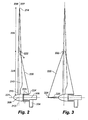
Thewind turbine 102 illustrated inFig. 1 is a modern conventional turbine that comprises atower 104 supporting a nacelle 106 (also called the windmill housing). A substantially horizontal main shaft projects from thenacelle 106, a rotor being mounted on said shaft, said rotor comprising ahub 108 and two ormore blades 110. The rotor can be made to rotate by the wind. Preferably, thewind turbine 102 is a so-called upwind turbine, where the wind impinges on the rotor before it impinges on thetower 104, and where thenacelle 106 is able to yaw, i.e. rotate around a vertical axis with respect to thetower 104, the rotor thereby adjusting itself to the wind direction at any given moment. Moreover, the wind turbine is preferably provided with threeblades 110 extending substantially radially outwards from thehub 108 and being formed as so-called shell bodies made of a polymer material reinforced with glass fibres, carbon fibres, or other reinforcement fibres. Eachblade 110 comprises aroot section 116 near thehub 108 and ablade tip 114.
The wind turbine shown inFig. 2 corresponds to the wind turbine shown inFig. 1 where like reference numerals refer to like parts. Therefore, only the differences are described here. The characteristic feature of the wind turbine shown inFig. 2 is that theblades 210, featuringinnermost parts 228 andoutermost parts 229, are supported onleeward sides 227 by supportingmeans 220 connected between first mountingpoints 222 located on theblades 210 with second mounting points 224 located in an axial distance from therotor plane 212. Note that only oneblade 210 is shown in the figure, while the others are omitted for clarity. The second mounting point 224 is located on anextension sleeve 225 that is mounted on thehub 208. Theextension sleeve 225 may rotate around ahorizontal axis 221, exterior to the nacelle 206. The nacelle 206 is rotatably mounted on thetower 204.
Fig. 3 shows a second embodiment that corresponds to the wind turbine shown inFig. 2 . Therefore, only the differences are described here. In this embodiment, the blades are supported on the leeward side as well as on the windward side by a first windward supporting means 330 that is connected to the blade in a firstwindward mounting point 332 and to a secondwindward mounting point 334 on ashaft extension 336. Theshaft extension 336 extends on the windward side of the hub to which it is preferably connected.
Fig. 4 shows the rotor assembly of a third embodiment of the invention. The wind turbine rotor assembly shown inFig. 4 corresponds to the wind turbines inFig. 2 and Fig. 3 , where like reference numerals refers to like parts. Therefore, only the differences are described here. According to this embodiment, theblades 410 of the wind turbine are supported on both the leeward and windward sides. Note that only two of theblades 410 are shown to simplify the figure. The characteristic feature of this embodiment is that eachblade 410 is provided with a first supporting means 420 having itsfirst mounting point 422 on or in proximity to aleading edge 440 of theblade 410, and an additional first supporting means 420 having itsfirst mounting point 422 on or in proximity to a trailingedge 441 of theblade 410. The two first mounting points 422 preferably have substantially the same radial distance from the hub. The two second mounting points 424 of the two first supporting means 420 are arranged in an axial distance from the rotor plane, e.g. on anextension sleeve 425 mounted to thehub 408. Furthermore, the blade may be provided with a set of first windward supporting means 430, having first windward mountingpoints 432 on or in proximity to, respectively, the leading 440 and trailingedge 441 of the blade. By using a set of two supportingmeans 420, connected to both the leading 440 and trailingedge 441 of the blade, the load on the supporting means 420 is substantially halved, and the load from the first mounting points 422 are displaced over a larger area of the blade, which leads to a stronger connection. Likewise, providing the blade with a set of two windward supporting means 430 substantially halves the load on the windward supporting means 430 and displaces the load applied in the firstwindward mounting points 432 over a larger area of the blade. The blade may of course be provided with multiple sets of supporting means, distributed along the length of the blade. It is also apparent to a person skilled in the art to, e.g. provide the blade with a set of two windward supporting means 430 and a single supporting means 420 on the leeward side to account for uneven loads on the two sides of the rotor plane. Thefirst mounting point 422 and the additionalfirst mounting point 422, and likewise for the firstwindward mounting points 432, may also be provided at different radial distances from thehub 408.
Fig. 5 shows a fourth embodiment of the invention, which corresponds to the wind turbine shown inFig. 2 where like reference numerals refer to like parts. Therefore, only the differences between the two embodiments are described here. In this embodiment the supportingmeans 520 is arranged to intersect a spacing means 550 that protrudes substantially normally to the rotor plane on the leeward side of the blade. Addition of a spacing means increases the angle a, which results in a smaller force needed along the supporting means 520 to achieve the same force in the horizontal direction, when compared to the situation without a spacing means. This follows from the relation F=P sin(a), where F is the force along the supportingmeans 520 and P is the force in the horizontal direction. To reduce drag and noise emissions, it may be advantageous to provide the spacing means 550 with a drag reducing profile (a "drop" profile). The spacing means must be dimensioned to withstand substantial compressible forces of the order of magnitude P. From this, it is evident that the blade may need to be reinforced in the area from where the supporting means extends. Naturally, the blade may be provided with multiple spacing means, to support the length of the innermost part of the blade.
Fig. 6 displays a fifth embodiment of the invention, and is described here with reference to the differences as compared toFig. 2 , where like reference numerals refer to like parts. According to this embodiment, the blade is divided in two parts, namely theinnermost part 628 and theoutermost part 629. Both parts are individually pitchable, i.e. may be rotated around their longitudinal axis. The first mounting point may be located towards the outer end of theinnermost part 628 of the blade, or on an intermediate part that separates theinnermost part 628 and theoutermost part 629, or even in proximity to the inner end of theoutermost part 629. Alternatively, only one of the blade parts is pitchable.
Fig. 7a and 7b shows two embodiments of thefirst mounting point 722, i.e. the mounting point of the supporting means to the blade. Since the blade part on which thefirst mounting point 722 is located may be pitchable, the relative direction of the supporting means 720 to the blade surface, or even the distance from the first mounting point to the second mounting point may differ. Therefore, care must be taken to allow the blade freedom to pitch, while being supported by the supporting means. According to the embodiment inFig. 7a , this problem is remedied by providing the supporting means with a ball joint, thereby allowing blade to turn with regard to the supportingmeans 720. An alternative solution is shown inFig. 7b , where the otherwise rigid supporting means 720 is provided with aflexible member 772, e.g. a spring, to account for changes in the distance between the mounting points at the two ends of the supporting means. It is apparent for a person skilled in the art that the blade may need to be reinforced in the area, where thefirst mounting point 722 is provided in order to withstand the forces imposed by the supportingmeans 720. It is also apparent that the two solutions shown inFig. 7a and 7b may be combined.
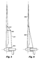
Fig. 8 displays a sixth embodiment of the invention, which corresponds to the wind turbine shown inFig. 2 . Therefore only the differences between the two embodiments are described here. In this embodiment, anacelle 880 is provided as a load bearing cylinder that supports agenerator 882 in one end, and the rotor in the other end. The rotor is connected to thegenerator 882 by amain shaft 886. The main bearing that supports the rotor is provided as abearing 884 between the outside of theload bearing cylinder 880 that forms the nacelle and an extension sleeve.
Fig. 9 shows a seventh embodiment of the invention, which corresponds to the wind turbine shown inFig. 2 . Therefore, only the differences between the two embodiments are described here. According to this embodiment, the second mounting points of the supporting means are mounted on arotatable ring 990 that may rotate freely around the nacelle, which is provided as aload bearing cylinder 980. Therotatable ring 990 is mounted to the nacelle by abearing 984.
Fig. 10 shows an eighth embodiment of the invention, which corresponds to the wind turbine shown inFig. 2 . Therefore, only the differences between the two embodiments are described here. According to this embodiment, the second mounting point 1024 of the first supporting means 1020 is located on the blade in proximity to the blade root. Furthermore, the blade one spacing means 1050, or as shown in the figure a spacing means 1050 and a second spacing means 1099. It is evident that the blade may comprise a higher number of spacing means, such as three, four, five or six. In a configuration according to this embodiment, one may consider it as if the second mounting point is located on the second spacing means 1099, which is then supported in the radial direction with an additional supporting means extending towards the blade root.
The examples have been described according to preferred embodiments. However, the invention is not limited to these embodiments. For example the blade may be provided with multiple supporting means. -
- a
- angle
- 102
- wind turbine
- 104, 204
- tower
- 106,206
- nacelle
- 108,208,408
- hub
- 110, 210, 410
- blade
- 114, 214
- blade tip
- 116, 216
- blade root
- 212
- rotor plane
- 220, 420, 520, 720, 1020
- supporting means
- 221
- horizontal axis
- 222, 422, 522, 722, 1022
- first mounting point
- 224, 424, 524, 1024
- second mounting point
- 225, 425
- extension sleeve
- 226
- windward side
- 227
- leeward side
- 228, 628
- innermost part
- 229, 629
- outermost part
- 330, 430
- windward supporting means
- 332, 432
- first windward mounting point
- 334, 434
- second windward mounting point
- 336, 436
- shaft extension
- 440
- leading edge
- 441
- trailing edge
- 550, 1050
- spacing means
- 770
- ball joint
- 772
- flexible member
- 880, 980
- load bearing cylinder
- 882
- generator
- 884, 984
- bearing
- 886
- main shaft
- 990
- rotatable ring
- 1099
- second spacing means
Claims (16)
- A wind turbine (102) comprising a number of blades (110, 210, 410) extending substantially radially from a hub (108, 208, 408) on a main shaft (886) having a substantially horizontal axis (221), the blades (110, 210, 410) together with the hub (108, 208, 408) constituting a rotor with a rotor plane (212), and which can be put into rotation by wind, the rotor during normal use of the wind turbine (102) having a windward side (226) and a leeward side (227), and each blade having an innermost part (228, 628) comprising a root section of the blade and an outermost part (229, 629) comprising a tip section of the blade, characterised in that each blade (110, 210, 410) is supported on the leeward side (227) by at least a first supporting means (220, 420, 520, 720, 1020) having a first end and a second end,- the first end being connected to the blade at a first mounting point (222, 422, 522, 722, 1022) positioned in a radial distance from the horizontal axis (221), and- the second end being connected to a second mounting point (224, 424, 524, 1024) at a rotatable part of the wind turbine (102), the second mounting point being positioned in an axial distance from the rotor plane (212) on the leeward side (227) of the rotor.
- A wind turbine (102) according to claim 1, wherein each blade (110, 210, 410) is supported on the windward side by at least a first windward supporting means (220, 420, 520, 720, 1020) having a first end and a second end,- the first end being connected to the blade at a first windward mounting point (332, 432) positioned in a radial distance from the hub (108, 208, 408), and- the second end being connected to a second windward mounting point (334, 434) at a rotatable part of the wind turbine (102), the second windward mounting point (334, 434) being positioned in an axial distance from the rotor plane (212) on the windward side (226) of the rotor.
- A wind turbine (102) according to any of the preceding claims, wherein the first supporting means (220, 420, 520, 720, 1020) and/or the first windward supporting means (220, 420, 520, 720, 1020) are chosen from the group of stays, stiffeners, guys, wires, or struts.
- A wind turbine (102) according to any of the preceding claims, wherein the first mounting point (222, 422, 522, 722, 1022) on the blade (110, 210, 410) is positioned in a radial distance of 20-100 % of the full length of the blade (110, 210, 410) from the hub (108, 208, 408), or alternatively between 25-70%, or yet alternatively between 30%-60%.
- A wind turbine (102) according to any of the preceding claims, wherein the blade is provided with the first mounting point (222, 422, 522, 722, 1022) in proximity to the leading edge (440) of the blade (110, 210, 410), and an additional first mounting point (222, 422, 522, 722, 1022) in proximity to the trailing edge (441) of the blade (110, 210, 410), the two first mounting points (222, 422, 522, 722, 1022) having substantially the same radial distance from the hub (108, 208, 408).
- A wind turbine (102) according to any of the preceding claims, wherein the blade is provided with at least a first spacing means (550, 1050) that protrudes substantially normally to the rotor plane (212) on the leeward side of the rotor, and where the spacing means intersects the first supporting means (220, 420, 520, 720, 1020).
- A wind turbine (102) according to claim 6, wherein the second mounting point (224, 424, 524, 1024) is located on the blade (110, 210, 410) in proximity to the blade root (116, 216).
- A wind turbine (102) according to any of the preceding claims, wherein the second mounting point (224, 424, 524) is located on an extension sleeve (225, 425) that is connectively mounted to the hub (108, 208, 408) on the leeward side of the rotor, so that the extension sleeve (225, 425) surrounds the main shaft (886) in a radial distance.
- A wind turbine (102) according to any of the preceding claims, wherein each blade (110, 210, 410) has a total length of at least 40 meters.
- A wind turbine (102) according to any of the preceding claims, wherein the innermost (228, 628) and outermost part (229, 629) of the blade (110, 210, 410) are constructed as two individual parts, where one or both parts may be pitched around a longitudinal axis of the blade (110, 210, 410), oriented in the substantially radial direction.
- A wind turbine (102) according to any of the preceding claims, wherein at least the first supporting means (220, 420, 520, 720, 1020) is provided with a swivel joint, such as a ball joint (772), or where at least part of the first supporting means (220, 420, 520, 720, 1020) is flexible.
- A wind turbine (102) according to any of the preceding claims, wherein the main shaft (886) is pivotally mounted in a nacelle (106, 206) mounted on top of a tower (104, 204), the nacelle (106, 206) being able to pivot around a vertical axis in relation to the tower (104, 204), hereby being able to adjust the rotor plane of the blades (110, 210, 410) in relation to a direction of the wind.
- A wind turbine (102) according to claim 12, wherein the nacelle comprises a load bearing cylinder (880, 980).
- A wind turbine (102) according to any of the claims 12-13, wherein the second mounting point (224, 424, 524, 1024) is located on a ring (990) that is rotatably mounted around the nacelle (106, 206), the ring being arranged substantially coaxially with the main shaft (886).
- A wind turbine (102) according to the claims 8 and 13, wherein the extension sleeve (225, 425) mounted on the hub (108, 208, 408) is rotatably mounted on the nacelle (106, 206) by a bearing (884, 984).
- A method of supporting blades (110, 210, 410) of a wind turbine (102) comprising a number of blades (110, 210, 410) extending substantially radially from a hub (108, 208, 408), the blades (110, 210, 410) together with the hub (108, 208, 408) constituting a rotor with a rotor plane (212), characterized by providing each blade (110, 210, 410) with at least a first supporting means (220, 420, 520, 720, 1020) on a leeward side (227) of the rotor plane (212), the first supporting means (220, 420, 520, 720, 1020) having a first end and a second end,- the first end being connected to the blade (110, 210, 410) at a first mounting point (222, 422, 522, 722, 1022) positioned in a radial distance from the horizontal axis (221), and- the second end being connected to a second mounting point (224, 424, 524, 1024) at a rotatable part of the wind turbine (102), the second mounting point (224, 424, 524, 1024) being positioned in an axial distance from the rotor plane (212) on a leeward side (227) of the rotor.
Priority Applications (5)
| Application Number | Priority Date | Filing Date | Title |
|---|---|---|---|
| EP20080388016 EP2112372A1 (en) | 2008-04-21 | 2008-04-21 | Wind turbine with blades supported on the leeward site |
| CN200980123519.6A CN102066746B (en) | 2008-04-21 | 2009-04-21 | Upwind wind turbine with blades supported on the leeward side |
| EP09734051.7A EP2304227B1 (en) | 2008-04-21 | 2009-04-21 | Upwind wind turbine with blades supported on the leeward side |
| US12/988,691 US9017034B2 (en) | 2008-04-21 | 2009-04-21 | Upwind wind turbine with blades supported on the leeward side |
| PCT/EP2009/054729 WO2009130212A1 (en) | 2008-04-21 | 2009-04-21 | Upwind wind turbine with blades supported on the leeward side |
Applications Claiming Priority (1)
| Application Number | Priority Date | Filing Date | Title |
|---|---|---|---|
| EP20080388016 EP2112372A1 (en) | 2008-04-21 | 2008-04-21 | Wind turbine with blades supported on the leeward site |
Publications (1)
| Publication Number | Publication Date |
|---|---|
| EP2112372A1 true EP2112372A1 (en) | 2009-10-28 |
Family
ID=40404874
Family Applications (2)
| Application Number | Title | Priority Date | Filing Date |
|---|---|---|---|
| EP20080388016 Withdrawn EP2112372A1 (en) | 2008-04-21 | 2008-04-21 | Wind turbine with blades supported on the leeward site |
| EP09734051.7A Not-in-force EP2304227B1 (en) | 2008-04-21 | 2009-04-21 | Upwind wind turbine with blades supported on the leeward side |
Family Applications After (1)
| Application Number | Title | Priority Date | Filing Date |
|---|---|---|---|
| EP09734051.7A Not-in-force EP2304227B1 (en) | 2008-04-21 | 2009-04-21 | Upwind wind turbine with blades supported on the leeward side |
Country Status (4)
| Country | Link |
|---|---|
| US (1) | US9017034B2 (en) |
| EP (2) | EP2112372A1 (en) |
| CN (1) | CN102066746B (en) |
| WO (1) | WO2009130212A1 (en) |
Cited By (8)
| Publication number | Priority date | Publication date | Assignee | Title |
|---|---|---|---|---|
| WO2014044855A1 (en) * | 2012-09-24 | 2014-03-27 | Joval Nv | A rotor assembly for a wind turbine |
| WO2014187933A2 (en) * | 2013-05-24 | 2014-11-27 | Joval Nv | A rotor assembly for a wind turbine comprising a pair of cables |
| DE202015100837U1 (en) | 2014-02-28 | 2015-03-20 | Horst Löwe | Wind turbine with days ahead of the rotor blades |
| US9822760B2 (en) | 2012-10-12 | 2017-11-21 | Joint Blade Rotor A/S | Joined blade wind turbine rotor |
| CN114588707A (en) * | 2022-03-15 | 2022-06-07 | 北京鑫龙创精密仪器有限公司 | Ventilation filter screen based on stainless steel ultrathin plate |
| WO2022128040A1 (en) * | 2020-12-17 | 2022-06-23 | Vestas Wind Systems A/S | A pitch controlled wind turbine with blade connecting members |
| WO2023078519A1 (en) * | 2021-11-04 | 2023-05-11 | Vestas Wind Systems A/S | A method for reducing blade vibrations in a wind turbine |
| WO2023078521A1 (en) * | 2021-11-04 | 2023-05-11 | Vestas Wind Systems A/S | A method for reducing blade flap loads in a wind turbine |
Families Citing this family (12)
| Publication number | Priority date | Publication date | Assignee | Title |
|---|---|---|---|---|
| US9709029B2 (en) | 2011-06-21 | 2017-07-18 | University Of Virginia Patent Foundation | Morphing segmented wind turbine and related method |
| CN102562485B (en) * | 2012-01-19 | 2014-04-02 | 清华大学 | Inhaul cable device used for reinforcing stability of blades of large wind driven generator |
| CN102536683B (en) * | 2012-01-19 | 2014-04-02 | 清华大学 | Zonal guy cable device used for enhancing blade stability of large-scale wind driven generator |
| KR101998423B1 (en) * | 2013-01-04 | 2019-07-09 | 두산중공업 주식회사 | Wind power generator including reinforcing structure and control method of the same |
| CN105298741B (en) * | 2015-11-03 | 2018-11-06 | 周方 | The reinforced blade of wind-driven generator |
| CN105298740B (en) * | 2015-11-03 | 2018-11-06 | 周方 | The rotor stiffening device of wind-driven generator |
| FR3064302B1 (en) * | 2017-03-23 | 2019-06-07 | Safran Aircraft Engines | CENTRAL SUPPORT OF TUBES SERVITUDE WITH ELASTIC RETURN |
| FR3072733B1 (en) * | 2017-10-24 | 2020-01-10 | Guy Euve | AEROGENERATOR |
| JP7369012B2 (en) * | 2019-11-20 | 2023-10-25 | 古野電気株式会社 | Channel optimization support device, channel optimization support method, access point management system, and program |
| WO2023237168A1 (en) * | 2022-06-10 | 2023-12-14 | Vestas Wind Systems A/S | A pitch controlled wind turbine |
| WO2023237167A1 (en) * | 2022-06-10 | 2023-12-14 | Vestas Wind Systems A/S | A pitch controlled wind turbine |
| CN116877323A (en) * | 2023-02-17 | 2023-10-13 | 清天新能源(北京)有限公司 | Wind wheel of steel rope net type wind driven generator |
Citations (7)
| Publication number | Priority date | Publication date | Assignee | Title |
|---|---|---|---|---|
| US2516576A (en) * | 1947-01-04 | 1950-07-25 | Charles R Jacobs | Self-governing wind-driven propeller |
| US4183715A (en) * | 1978-02-01 | 1980-01-15 | First National Bank Of Lubbock | Adjustable vane windmills |
| GB1592114A (en) * | 1976-08-26 | 1981-07-01 | Praktisk Teknik Ab | Rotors preferably for wind power stations |
| US4316699A (en) * | 1979-08-24 | 1982-02-23 | Schott Lawrence A | Windmill structure and power generator |
| US4403916A (en) | 1980-09-02 | 1983-09-13 | Chicago Province Of The Society Of Jesus | Wind turbines |
| WO1986002701A1 (en) | 1984-11-01 | 1986-05-09 | Christian Riisager | A windmill rotor with adjustable-pitch blades, as well as windmills with such a rotor |
| US5354175A (en) * | 1992-03-16 | 1994-10-11 | Northern Power Systems, Inc. | Wind turbine rotor hub and teeter joint |
Family Cites Families (6)
| Publication number | Priority date | Publication date | Assignee | Title |
|---|---|---|---|---|
| US493060A (en) * | 1893-03-07 | bowman | ||
| US300161A (en) * | 1884-06-10 | Windmill | ||
| US432435A (en) * | 1890-07-15 | Windmill | ||
| BR0207714B1 (en) * | 2001-12-28 | 2011-05-17 | wind turbine and method of operation. | |
| AUPS266702A0 (en) * | 2002-05-30 | 2002-06-20 | O'connor, Arthur | Improved turbine |
| DE102004052598A1 (en) * | 2004-10-29 | 2006-05-04 | Aktiebolaget Skf | Wind turbine |
-
2008
- 2008-04-21 EP EP20080388016 patent/EP2112372A1/en not_active Withdrawn
-
2009
- 2009-04-21 CN CN200980123519.6A patent/CN102066746B/en not_active Expired - Fee Related
- 2009-04-21 US US12/988,691 patent/US9017034B2/en active Active
- 2009-04-21 WO PCT/EP2009/054729 patent/WO2009130212A1/en active Application Filing
- 2009-04-21 EP EP09734051.7A patent/EP2304227B1/en not_active Not-in-force
Patent Citations (7)
| Publication number | Priority date | Publication date | Assignee | Title |
|---|---|---|---|---|
| US2516576A (en) * | 1947-01-04 | 1950-07-25 | Charles R Jacobs | Self-governing wind-driven propeller |
| GB1592114A (en) * | 1976-08-26 | 1981-07-01 | Praktisk Teknik Ab | Rotors preferably for wind power stations |
| US4183715A (en) * | 1978-02-01 | 1980-01-15 | First National Bank Of Lubbock | Adjustable vane windmills |
| US4316699A (en) * | 1979-08-24 | 1982-02-23 | Schott Lawrence A | Windmill structure and power generator |
| US4403916A (en) | 1980-09-02 | 1983-09-13 | Chicago Province Of The Society Of Jesus | Wind turbines |
| WO1986002701A1 (en) | 1984-11-01 | 1986-05-09 | Christian Riisager | A windmill rotor with adjustable-pitch blades, as well as windmills with such a rotor |
| US5354175A (en) * | 1992-03-16 | 1994-10-11 | Northern Power Systems, Inc. | Wind turbine rotor hub and teeter joint |
Cited By (14)
| Publication number | Priority date | Publication date | Assignee | Title |
|---|---|---|---|---|
| WO2014044855A1 (en) * | 2012-09-24 | 2014-03-27 | Joval Nv | A rotor assembly for a wind turbine |
| BE1021430B1 (en) * | 2012-09-24 | 2015-11-19 | Joval Nv | A ROTOR WHOLE FOR A WIND TURBINE |
| US9759182B2 (en) | 2012-09-24 | 2017-09-12 | Joval Nv | Rotor assembly for a wind turbine |
| US9822760B2 (en) | 2012-10-12 | 2017-11-21 | Joint Blade Rotor A/S | Joined blade wind turbine rotor |
| WO2014187933A2 (en) * | 2013-05-24 | 2014-11-27 | Joval Nv | A rotor assembly for a wind turbine comprising a pair of cables |
| WO2014187933A3 (en) * | 2013-05-24 | 2015-01-08 | Joval Nv | A rotor assembly for a wind turbine comprising a pair of cables |
| US10087914B2 (en) | 2013-05-24 | 2018-10-02 | Joval Nv | Rotor assembly for a wind turbine comprising a pair of cables |
| DE202015100837U1 (en) | 2014-02-28 | 2015-03-20 | Horst Löwe | Wind turbine with days ahead of the rotor blades |
| DE102015102461A1 (en) | 2014-02-28 | 2015-09-03 | Horst Löwe | Wind turbine with days ahead of the rotor blades |
| WO2022128040A1 (en) * | 2020-12-17 | 2022-06-23 | Vestas Wind Systems A/S | A pitch controlled wind turbine with blade connecting members |
| WO2023078519A1 (en) * | 2021-11-04 | 2023-05-11 | Vestas Wind Systems A/S | A method for reducing blade vibrations in a wind turbine |
| WO2023078521A1 (en) * | 2021-11-04 | 2023-05-11 | Vestas Wind Systems A/S | A method for reducing blade flap loads in a wind turbine |
| CN114588707A (en) * | 2022-03-15 | 2022-06-07 | 北京鑫龙创精密仪器有限公司 | Ventilation filter screen based on stainless steel ultrathin plate |
| CN114588707B (en) * | 2022-03-15 | 2023-09-12 | 北京鑫龙创精密仪器有限公司 | Ventilating filter screen based on stainless steel ultrathin plate |
Also Published As
| Publication number | Publication date |
|---|---|
| EP2304227B1 (en) | 2016-01-06 |
| EP2304227A1 (en) | 2011-04-06 |
| US9017034B2 (en) | 2015-04-28 |
| US20110031763A1 (en) | 2011-02-10 |
| CN102066746A (en) | 2011-05-18 |
| WO2009130212A1 (en) | 2009-10-29 |
| CN102066746B (en) | 2015-04-01 |
Similar Documents
| Publication | Publication Date | Title |
|---|---|---|
| EP2304227B1 (en) | Upwind wind turbine with blades supported on the leeward side | |
| US8465256B2 (en) | Wind turbine rotor | |
| US7713028B2 (en) | Turbine blade assembly | |
| US8011887B2 (en) | Rotor blade assembly | |
| US10253751B2 (en) | Wind turbine blade assembled from inboard part and outboard part having different types of load carrying structures | |
| US20090148291A1 (en) | Multi-section wind turbine rotor blades and wind turbines incorporating same | |
| EP2075464A2 (en) | Forward leaning tower top section | |
| US8714928B2 (en) | Rotor assembly for a wind turbine and method of assembling the same | |
| KR20070116107A (en) | Tension wheel in a rotor system for wind and water turbines | |
| US8562300B2 (en) | Wind turbine with high solidity rotor | |
| US20210102526A1 (en) | Method for mounting rotor blades of a wind turbine | |
| JP2020084812A (en) | Windmill blade and wind power generation device | |
| US20220252040A1 (en) | Wind turbine and wind turbine rotor blade |
Legal Events
| Date | Code | Title | Description |
|---|---|---|---|
| PUAI | Public reference made under article 153(3) epc to a published international application that has entered the european phase |
Free format text: ORIGINAL CODE: 0009012 |
|
| AK | Designated contracting states |
Kind code of ref document: A1 Designated state(s): AT BE BG CH CY CZ DE DK EE ES FI FR GB GR HR HU IE IS IT LI LT LU LV MC MT NL NO PL PT RO SE SI SK TR |
|
| AX | Request for extension of the european patent |
Extension state: AL BA MK RS |
|
| AKX | Designation fees paid | ||
| REG | Reference to a national code |
Ref country code: DE Ref legal event code: 8566 |
|
| STAA | Information on the status of an ep patent application or granted ep patent |
Free format text: STATUS: THE APPLICATION IS DEEMED TO BE WITHDRAWN |
|
| 18D | Application deemed to be withdrawn |
Effective date: 20100429 |
|
| P01 | Opt-out of the competence of the unified patent court (upc) registered |
Effective date: 20230522 |