EP2065299A1 - Seetransport von Windturbinenblättern - Google Patents
Seetransport von Windturbinenblättern Download PDFInfo
- Publication number
- EP2065299A1 EP2065299A1 EP07388086A EP07388086A EP2065299A1 EP 2065299 A1 EP2065299 A1 EP 2065299A1 EP 07388086 A EP07388086 A EP 07388086A EP 07388086 A EP07388086 A EP 07388086A EP 2065299 A1 EP2065299 A1 EP 2065299A1
- Authority
- EP
- European Patent Office
- Prior art keywords
- wind turbine
- turbine blade
- blade
- blades
- water
- Prior art date
- Legal status (The legal status is an assumption and is not a legal conclusion. Google has not performed a legal analysis and makes no representation as to the accuracy of the status listed.)
- Granted
Links
Images


Classifications
-
- B—PERFORMING OPERATIONS; TRANSPORTING
- B63—SHIPS OR OTHER WATERBORNE VESSELS; RELATED EQUIPMENT
- B63B—SHIPS OR OTHER WATERBORNE VESSELS; EQUIPMENT FOR SHIPPING
- B63B35/00—Vessels or similar floating structures specially adapted for specific purposes and not otherwise provided for
- B63B35/003—Vessels or similar floating structures specially adapted for specific purposes and not otherwise provided for for transporting very large loads, e.g. offshore structure modules
-
- B—PERFORMING OPERATIONS; TRANSPORTING
- B63—SHIPS OR OTHER WATERBORNE VESSELS; RELATED EQUIPMENT
- B63B—SHIPS OR OTHER WATERBORNE VESSELS; EQUIPMENT FOR SHIPPING
- B63B21/00—Tying-up; Shifting, towing, or pushing equipment; Anchoring
- B63B21/56—Towing or pushing equipment
-
- B—PERFORMING OPERATIONS; TRANSPORTING
- B63—SHIPS OR OTHER WATERBORNE VESSELS; RELATED EQUIPMENT
- B63B—SHIPS OR OTHER WATERBORNE VESSELS; EQUIPMENT FOR SHIPPING
- B63B77/00—Transporting or installing offshore structures on site using buoyancy forces, e.g. using semi-submersible barges, ballasting the structure or transporting of oil-and-gas platforms
- B63B77/10—Transporting or installing offshore structures on site using buoyancy forces, e.g. using semi-submersible barges, ballasting the structure or transporting of oil-and-gas platforms specially adapted for electric power plants, e.g. wind turbines or tidal turbine generators
-
- F—MECHANICAL ENGINEERING; LIGHTING; HEATING; WEAPONS; BLASTING
- F03—MACHINES OR ENGINES FOR LIQUIDS; WIND, SPRING, OR WEIGHT MOTORS; PRODUCING MECHANICAL POWER OR A REACTIVE PROPULSIVE THRUST, NOT OTHERWISE PROVIDED FOR
- F03D—WIND MOTORS
- F03D1/00—Wind motors with rotation axis substantially parallel to the air flow entering the rotor
- F03D1/06—Rotors
-
- F—MECHANICAL ENGINEERING; LIGHTING; HEATING; WEAPONS; BLASTING
- F03—MACHINES OR ENGINES FOR LIQUIDS; WIND, SPRING, OR WEIGHT MOTORS; PRODUCING MECHANICAL POWER OR A REACTIVE PROPULSIVE THRUST, NOT OTHERWISE PROVIDED FOR
- F03D—WIND MOTORS
- F03D13/00—Assembly, mounting or commissioning of wind motors; Arrangements specially adapted for transporting wind motor components
- F03D13/20—Arrangements for mounting or supporting wind motors; Masts or towers for wind motors
- F03D13/25—Arrangements for mounting or supporting wind motors; Masts or towers for wind motors specially adapted for offshore installation
-
- F—MECHANICAL ENGINEERING; LIGHTING; HEATING; WEAPONS; BLASTING
- F03—MACHINES OR ENGINES FOR LIQUIDS; WIND, SPRING, OR WEIGHT MOTORS; PRODUCING MECHANICAL POWER OR A REACTIVE PROPULSIVE THRUST, NOT OTHERWISE PROVIDED FOR
- F03D—WIND MOTORS
- F03D13/00—Assembly, mounting or commissioning of wind motors; Arrangements specially adapted for transporting wind motor components
- F03D13/40—Arrangements or methods specially adapted for transporting wind motor components
-
- F—MECHANICAL ENGINEERING; LIGHTING; HEATING; WEAPONS; BLASTING
- F05—INDEXING SCHEMES RELATING TO ENGINES OR PUMPS IN VARIOUS SUBCLASSES OF CLASSES F01-F04
- F05B—INDEXING SCHEME RELATING TO WIND, SPRING, WEIGHT, INERTIA OR LIKE MOTORS, TO MACHINES OR ENGINES FOR LIQUIDS COVERED BY SUBCLASSES F03B, F03D AND F03G
- F05B2240/00—Components
- F05B2240/90—Mounting on supporting structures or systems
- F05B2240/95—Mounting on supporting structures or systems offshore
-
- F—MECHANICAL ENGINEERING; LIGHTING; HEATING; WEAPONS; BLASTING
- F16—ENGINEERING ELEMENTS AND UNITS; GENERAL MEASURES FOR PRODUCING AND MAINTAINING EFFECTIVE FUNCTIONING OF MACHINES OR INSTALLATIONS; THERMAL INSULATION IN GENERAL
- F16C—SHAFTS; FLEXIBLE SHAFTS; ELEMENTS OR CRANKSHAFT MECHANISMS; ROTARY BODIES OTHER THAN GEARING ELEMENTS; BEARINGS
- F16C2360/00—Engines or pumps
- F16C2360/31—Wind motors
-
- Y—GENERAL TAGGING OF NEW TECHNOLOGICAL DEVELOPMENTS; GENERAL TAGGING OF CROSS-SECTIONAL TECHNOLOGIES SPANNING OVER SEVERAL SECTIONS OF THE IPC; TECHNICAL SUBJECTS COVERED BY FORMER USPC CROSS-REFERENCE ART COLLECTIONS [XRACs] AND DIGESTS
- Y02—TECHNOLOGIES OR APPLICATIONS FOR MITIGATION OR ADAPTATION AGAINST CLIMATE CHANGE
- Y02E—REDUCTION OF GREENHOUSE GAS [GHG] EMISSIONS, RELATED TO ENERGY GENERATION, TRANSMISSION OR DISTRIBUTION
- Y02E10/00—Energy generation through renewable energy sources
- Y02E10/70—Wind energy
- Y02E10/72—Wind turbines with rotation axis in wind direction
-
- Y—GENERAL TAGGING OF NEW TECHNOLOGICAL DEVELOPMENTS; GENERAL TAGGING OF CROSS-SECTIONAL TECHNOLOGIES SPANNING OVER SEVERAL SECTIONS OF THE IPC; TECHNICAL SUBJECTS COVERED BY FORMER USPC CROSS-REFERENCE ART COLLECTIONS [XRACs] AND DIGESTS
- Y02—TECHNOLOGIES OR APPLICATIONS FOR MITIGATION OR ADAPTATION AGAINST CLIMATE CHANGE
- Y02E—REDUCTION OF GREENHOUSE GAS [GHG] EMISSIONS, RELATED TO ENERGY GENERATION, TRANSMISSION OR DISTRIBUTION
- Y02E10/00—Energy generation through renewable energy sources
- Y02E10/70—Wind energy
- Y02E10/727—Offshore wind turbines
Definitions
- the present invention relates to transportation of blades for wind turbines.
- fixtures are used. These fixtures are customized and thereby unique for every blade type, for which reason every new type of blade requires new and different fixtures. Furthermore, the curvature of the blades makes them difficult to stack in a cost efficient manner.
- the fixtures are welded onto the deck of the ship and designed in a way enabling a stacking of the blades in three to four layers. Due to the customization of the fixtures and the elaborate procedures encumbered therewith, seaborne carriage of wind turbine blades is associated with high costs.
- the objective of the present invention is to propose methods for transporting wind turbine blades. Furthermore, it is an object of this invention to eliminate or at least diminish the above mentioned problems by providing a low-cost, simple, and highly efficient way of transporting wind turbine blades.
- the present invention relates to a method for transporting a blade for a wind turbine, comprising the steps of lowering said wind turbine blade into water, whereby it floats, and transporting said blade in the water.
- the proposed method is advantageous by providing a simple, inexpensive and fast way of transporting wind turbine blades, as the blades are simply lowered in water without, in the simplest case, any further arrangements.
- the blades can be transported alone or in groups. Furthermore, the transportation of the blades can constitute just a part of the way from the manufacturing site to the installation site, whereas wind turbine blades for both onshore and offshore installations can be transported in this way. Blades for offshore wind turbines can also be transported directly to the installation location, even if this is in areas with a low water level.
- the crane lifting the blades when mounting these can be positioned in proximity of the erected tower and nacelle. Each time a blade has been mounted, the next blade can simply be moved into the lifting-range of the crane. Therefore the crane does not have to move back and forth between the ship carrying the blades and the location of the offshore wind turbine.
- the blades for an offshore wind turbine can also be mounted by the use of a lifting device placed in the hub, wired to the blade root. By means of the wires the blade is simply hoisted to the hub bearing and fastened thereto. Thus there is no need for cranes.
- Offshore wind turbines are most often placed in water depths of 10-15m. Therefore, during this hoisting movement of an offshore blade, the tip of the blade will eventually hit the seabed. In order to avoid this potentially damaging impact, the outermost part of the blade can be supported by a rubber boat or other supporting means. In the case of an onshore wind turbine, the blade can be hoisted in a similar way and the blade tip supported by a truck, trailer or other means.
- Another advantage is that there are no limitations on the length or weight of the wind turbine blades. Moreover, this kind of transportation does not disturb road users and requires no special and expensive fixtures as with the present seaborne carriage. In continuation of this, many of the elaborate working procedures can also be eliminated.
- the invention is further advantageous providing transportation where the blade is free to flex and deform without the risk of damage. From the range of advantages listed above it is clear that this method for transporting wind turbine blades in water is inexpensive and thereby a low cost alternative compared to the possibilities known in the state of the art.
- said method comprises sealing at least one opening in said wind turbine blade such as a opening in the root end of the wind turbine or drain holes along the wind turbine blade in a watertight way, such that said wind turbine blade can be transported floating in water and where said at least one opening can be at least partly restored after transportation.
- said method comprises towing at least one wind turbine blade by a vessel, such as a towboat.
- a vessel such as a towboat.
- said method comprises transporting a plurality of wind turbine blades in water in single file behind a vessel. This particular way of transporting is advantageous in narrow or low waters such as a rivers and canals.
- said method comprises transporting a plurality of wind turbine blades in water side-by-side behind a vessel.
- said method comprises fastening at least one stabilizing unit to said blade. This is advantageous when the blades are transported through e.g. troubled water.
- said method comprises fastening at least one propelling means to said blade.
- said method comprises fastening at least one towing means to said blade.
- said method comprises fastening at least one protecting unit, such as a fender, to said blade.
- at least one protecting unit such as a fender
- the present invention relates to a wind turbine blade for a wind turbine, wherein at least one opening in said wind turbine blade such as a opening in the root end of the wind turbine blade or drain holes along the wind turbine blade has been sealed in a watertight way, such that said wind turbine blade can be transported floating in water and where said at least one opening is at least partly restored after transportation.
- at least one opening in said wind turbine blade such as a opening in the root end of the wind turbine blade or drain holes along the wind turbine blade has been sealed in a watertight way, such that said wind turbine blade can be transported floating in water and where said at least one opening is at least partly restored after transportation.
- said wind turbine blade comprises at least one keel detachably fastened to said wind turbine blade. This is advantageous as it stabilizes the blade in the water.
- said wind turbine blade comprises at least one stabilizer unit detachably fastened to said wind turbine blade. This is also advantageous as it stabilizes the blade in the water.
- said wind turbine blade comprises at least one detachable propelling means.
- said wind turbine blade comprises at least one detachable propelling means.
- said wind turbine blade comprises at least one rudder detachably fastened to said wind turbine blade such that said wind power can be navigated. This also serves to improve the maneuverability of the blades.
- said wind turbine blade comprises at least one fitting detachably fastened to said wind turbine blade for connecting at least one other wind turbine blade to said wind turbine blade such that the connected wind turbine blades can be transported jointly in water. This is advantageous as a plurality of blades can be transported over very long distances.
- FIG 1 illustrates a wind turbine blade 100 floating in water.
- Modem blades are most often hollow, which means that they can float.
- modem blades are made of glass and/or carbon fibers and different core materials such as balsa tree, foamed materials, of which all materials are resistant to water.
- the net upward buoyancy force on the wind turbine blade is equal to the magnitude of the weight of fluid displaced by the wind turbine blade. This force enables the wind turbine blade to float.
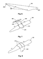
- FIG. 2 illustrates a towboat 210 towing a number of floating wind turbine blades 100 arranged in a single file manner.
- Each wind turbine blade 100 is mounted with one or more fittings 214 used for connecting the wind turbine blades 100 together with a blade connection 216.
- the fitting 214 can e.g. be a belt or a clamp which is fastened to the blade 100 and can comprise e.g. one or more fastening means (not shown) such as rings for securing the blade connection 216, hawsers and towlines 212, etc.
- the fitting 214 can also be fixed in permanent fastening members (not shown) in the blade 100 or fastened directly in the blade 100 using e.g. screws (not shown), where after the holes from the screws could be closed.
- the blade connection 216 connects each of the wind turbine blades 100 to each other in e.g. the fittings 214 or in the blade root (not shown).
- the blade connection 216 can e.g. be a simple towline of hawser, in which the case the fittings 214 can be omitted and replaced by tying the blade connection 216 directly to the blade 100.
- the blade connection 214 can also be rigid such that a constant distance between each of the connected wind turbine blades 100 is kept.
- the blade connection 214 can have the shape of a bar or an arc, and be made of metal, glass fibre, rigid rope, etc.
- a constant distance between the wind turbine blades 100 is advantageous in order to ensure that the wind turbine blades 100 do not damage each other during the transportation
- a rigid blade connection 214 ensures that the wind turbine blades 100 cannot move in a way not intended.
- the wind turbine blade 100 closest to the towboat 210 is connected thereto by the towline 212.
- This connection may also be rigid to ensure a safety distance between the towboat 210 and the wind turbine blade 100, and to obtain a sufficient maneuverability of both towboat 210 and the connected wind turbine blades 100.
- the wind turbine blades 100 can also be transported in reverse order, such that the blade tip would be in front. Regardless of how and with what means the wind turbine blades 100 are transported, the blades ability to float is exploited.
- FIG. 3 illustrates a towboat 210 towing a number of floating wind turbine blades 100 arranged side-by-side.
- Each wind turbine blade 100 is mounted with a fitting (not indicated) used for connecting the wind turbine blades 100 together with one or more blade connections 320.
- Each end of the blade connection 320 is connected to the fittings (not indicated) of neighboring wind turbine blades 100.
- the blade connection 216 can e.g. be a simple towline of hawser, in which case the fittings (not indicated) can be omitted and replaced by tying the blade connection 320 directly to the blade 100.
- each other fenders can be arranged between the blades 100.
- the blade connection 320 can also be rigid such that a constant distance between each of the connected wind turbine blades 100 is kept. Again, the constant distance between the wind turbine blades 100 is advantageous in order to ensure that the wind turbine blades 100 do not damage each other during the transportation. Furthermore the blade connection 320 ensures that the wind turbine blades 100 cannot move in ways not intended.
- the wind turbine blades 100 are rigidly connected to the towboat via the towline 212, fastened to the root sealing (not indicated) of the wind turbine blades 100.
- This towline 212 can likewise also rigid ensure a safety distance between the towboat 210 and the wind turbine blade 100, and to obtain a sufficient maneuverability of both towboat 210 and the connected wind turbine blades 100.
- the towline 212 can also be flexible like an ordinary towline or a hawser, and may be directly tied to the blade 100.
- the blade connections 320 can also be fastened to permanent fastening members (not shown) in the blade 100.
- Figure 4 illustrates the tower 440 and nacelle 442 of an offshore wind turbine with a floating wind turbine blade 100 at its side.
- the wind turbine blade 100 may be lifted in e.g. the fittings 214, such that the blade root can be fastened to one of the wind turbine blade bearings 446 in the wind turbine nacelle 442.
- the fittings 214 are similar to the ones described above (see description of figure 2 ).
- the wind turbine blade 100 can be lifted by for example an offshore crane (not shown) located in the proximity of the wind turbine or by a helicopter. As the wind turbine blades are floating in the water and can be easily moved around the offshore crane can maintain its position during the whole installation of the wind turbine blades 100.
- Figure 5 illustrates a wind turbine blade 100 adapted to be transported in water, wherein a propelling module 550 has been fastened to the root of the wind turbine blade 100, and side propeller 560 and rudder 570 fastened to the tip end of the blade 100.
- the propelling module 550 can be fastened to the blade root, and comprises a propeller 552, whereby the wind turbine blade 100 can be moved through the water.
- the propeller 552 can optionally be pivoted around an axis (not shown) perpendicular to the rotational axis of the propeller 552, whereby the floating wind turbine blade 100 can be moved in a desired direction.
- the propelling module 550 may be controlled remotely or be manned by a trained operator.
- the maneuverability of the wind turbine blade 100 can be further increased by mounting the blade 100 with a side propeller module 560 and/or a rudder module 570.
- the side propeller module 560 may comprise a fitting 564 used for mounting the side propeller module 560 on the wind turbine blade 100 and propeller 562.
- the propeller 562 can be pivoted around an axis (not shown) perpendicular to the rotational axis of the propeller 562.
- the rudder module can 570 comprise a rudder 572 and a rudder fitting for mounting the rudder module 570 around the wind turbine blade 100.
- the rudder module increases the maneuverability of the wind turbine blade 100 in water, and can therefore the purposefully used in narrow water such as in harbors or at the installation location of an offshore wind turbine, and at open sea where a continuous adjustment of the rudder can compensate for current and weather conditions.
- Both the side propeller module 560 and the rudder module 570 can be detached after use, and need not be attached near the tip as shown in the figure, but can be arranged anywhere along the blade.
- the side propeller module 560 and the rudder module 570 do not necessarily have to be mounted on a wind turbine blade 500 fastened to a propelling module, but can be applied to a wind turbine blade towed by e.g. a towboat.
- side propeller module 560 and the rudder module 570 have to be mounted in combination, but can be used a single module as well.
- a wind turbine blade can also be mounted with a plurality of side propeller modules 560 and rudder modules 570.
- the propelling module 550, side propeller module 560, and the rudder module 570 can also be fixed directly in the blade 100 with e.g. screws (not shown). When the modules are no longer needed, the holes from screws can be closed.
- the modules 550, 560, 570 could also be fixed to the blade 100 using permanent fastening members (not shown) in the blade 100.
- Figure 6 illustrates a wind turbine blade 100 comprising the openings at the root end 680, drain holes 682, and lightening conductor 684.
- these openings 680, 682 and the lightening conductor 684 Prior to transporting the blade 100 these openings 680, 682 and the lightening conductor 684 can optionally be sealed or covered in a way that they openings and the lightening conductor can be at least partly restored.
- the blade 100 could be arranged in a bag (not shown), or at least partly be wrapped with e.g. tape or another elastic and/or adhesive material (not shown).
- the openings 680, 682 and the lightening conductor 684 could also be padded with a material that could be optionally removed in order to restore these. Regardless of whether the seals or covers are applied, the blade 100 maintains its buoyancy.
- the drain holes 682 and the lightening conductor 684 can also be drilled and mounted, respectively, after the blade 100 has been transported to its end station, that is the installation location of the wind turbine (not shown).
- the root opening 680 could be sealed using a plane plate or a have a shape suited for hydrodynamic conditions.
- the root sealing could for example be shaped as a stem bulb.
- the blade 100 could at least partly be filled with water (not shown) in order to stabilize it when floating. In this way the inside of the blade would have a function resembling ballast water tanks in e.g. ships and vessels.
- this embodiment could also be realized by arranging a bag (not shown) inside the blade 100 and then at least partly fill this bag with water.
- Figure 7 illustrates a floating wind turbine blade 100 mounted with a stabilizing unit 790.
- the stabilizing unit 790 is fastened to the blade 100 with a blade connection 320 similar to the ones described in figure 3 .
- One end of the blade connection 320 is fastened to the fittings 214, which again are fastened to the blade 100.
- the other end of the blade connection 320 is fastened directly the stabilizing unit 790.
- the stabilizing unit 790 can be any element having buoyancy, such as a glass fibre structure.
- the stabilizing unit 790 advantageously has a hydrodynamic shape suited for transportation is water.
- the stabilizing unit 790 stabilizes the transportation of the blade 100, and, among others, prevents the blade 100 from twisting in the water.
- the keel 830 could also be fastened directly in the blade 100, using e.g. screws (not shown). When the keel 830 is no longer needed the holes from the screws are closed.
- Figure 8 illustrates a wind turbine blade 100 adapted to be transported in water, on which blade a detachable keel 830 has been mounted.
- the keel 830 has been mounted to the blade 100 by fittings 214 fastened to the blade 100.
- the purpose of the keel 830 is to stabilize the transportation of the blade 100 in water, by among others preventing it from twisting in the water.
- the keel 830 can be removed prior to its installation, as the aerodynamic shape of the blades 100 is important for the efficiency of the wind turbine.
- Figure 9 illustrates a wind turbine blade 100 arranged inside a sealed bag 999 floating in water.
- the bag 999 is inflatable and comprises a keel 997 and compartments 998, where the keel 997 stabilizes the bag and the compartments 998 provide additional buoyancy. Both the keel 997 and compartments 998 can be optionally inflated. Instead of inflating the bag 999, a partly vacuum can also be established in the bag 999.
Priority Applications (8)
| Application Number | Priority Date | Filing Date | Title |
|---|---|---|---|
| DE602007011952T DE602007011952D1 (de) | 2007-11-27 | 2007-11-27 | Seetransport von Windturbinenblättern |
| AT07388086T ATE495092T1 (de) | 2007-11-27 | 2007-11-27 | Seetransport von windturbinenblättern |
| DK07388086.6T DK2065299T3 (da) | 2007-11-27 | 2007-11-27 | Søtransport af vindmøllevinger |
| EP07388086A EP2065299B1 (de) | 2007-11-27 | 2007-11-27 | Seetransport von Windturbinenblättern |
| ES07388086T ES2358756T3 (es) | 2007-11-27 | 2007-11-27 | Transporte marítimo de palas de turbinas eólicas. |
| CN200880117914.9A CN101883713B (zh) | 2007-11-27 | 2008-11-03 | 风轮机叶片的海上运输 |
| US12/742,181 US8839733B2 (en) | 2007-11-27 | 2008-11-03 | Seaborne transportation of wind turbine blades |
| PCT/DK2008/000390 WO2009068031A1 (en) | 2007-11-27 | 2008-11-03 | Seaborne transportation of wind turbine blades |
Applications Claiming Priority (1)
| Application Number | Priority Date | Filing Date | Title |
|---|---|---|---|
| EP07388086A EP2065299B1 (de) | 2007-11-27 | 2007-11-27 | Seetransport von Windturbinenblättern |
Publications (2)
| Publication Number | Publication Date |
|---|---|
| EP2065299A1 true EP2065299A1 (de) | 2009-06-03 |
| EP2065299B1 EP2065299B1 (de) | 2011-01-12 |
Family
ID=39434139
Family Applications (1)
| Application Number | Title | Priority Date | Filing Date |
|---|---|---|---|
| EP07388086A Not-in-force EP2065299B1 (de) | 2007-11-27 | 2007-11-27 | Seetransport von Windturbinenblättern |
Country Status (8)
| Country | Link |
|---|---|
| US (1) | US8839733B2 (de) |
| EP (1) | EP2065299B1 (de) |
| CN (1) | CN101883713B (de) |
| AT (1) | ATE495092T1 (de) |
| DE (1) | DE602007011952D1 (de) |
| DK (1) | DK2065299T3 (de) |
| ES (1) | ES2358756T3 (de) |
| WO (1) | WO2009068031A1 (de) |
Cited By (3)
| Publication number | Priority date | Publication date | Assignee | Title |
|---|---|---|---|---|
| US8602700B2 (en) | 2012-02-16 | 2013-12-10 | General Electric Company | Shipping fixture and method for transporting rotor blades |
| EP2381099A3 (de) * | 2010-04-23 | 2014-05-14 | General Electric Company | Packungsfolie für Windturbinenteile, Verfahren zum Einpacken eines Windturbinenteils sowie Windturbinenmontage |
| WO2019001659A1 (en) * | 2017-06-30 | 2019-01-03 | Vestas Wind Systems A/S | METHOD OF SERVICING A WIND TURBINE |
Citations (4)
| Publication number | Priority date | Publication date | Assignee | Title |
|---|---|---|---|---|
| DE19621485A1 (de) * | 1996-05-29 | 1998-03-12 | Schulte Franz Josef | Rotorblattheizung für Windkraftanlagen |
| EP1469198A1 (de) * | 2003-04-17 | 2004-10-20 | Eugen Radtke | Auftriebsverbessernde Oberflächenstruktur für Windenergiekonverter |
| WO2005035978A1 (de) * | 2003-10-10 | 2005-04-21 | Repower Systems Ag | Rotorblatt für eine windkraftanlage |
| WO2007122376A1 (en) * | 2006-04-13 | 2007-11-01 | Alan West | Offshore apparatus for capturing energy |
Family Cites Families (12)
| Publication number | Priority date | Publication date | Assignee | Title |
|---|---|---|---|---|
| JPH1128495A (ja) * | 1997-07-14 | 1999-02-02 | Mitsubishi Heavy Ind Ltd | 水流発生装置 |
| GB2344843B (en) * | 1998-12-18 | 2002-07-17 | Neven Joseph Sidor | Gravity securing system for offshore generating equipment |
| NL1016986C2 (nl) * | 2000-12-22 | 2002-07-01 | Beheersmij P Buitendijk B V | Mastconstructie alsmede werkwijze voor het plaatsen daarvan. |
| WO2003004869A1 (en) * | 2001-07-06 | 2003-01-16 | Vestas Wind Systems A/S | Offshore wind turbine with floating foundation |
| JP2003252288A (ja) * | 2002-02-27 | 2003-09-10 | Hitachi Zosen Corp | 洋上風力発電の浮体式基礎構造物 |
| DE60225482T2 (de) * | 2002-05-27 | 2009-02-26 | Vestas Wind Systems A/S | Verfahren zur befestigung einer windturbine, windturbinenfundament und windturbinenanordnung |
| DK175261B1 (da) * | 2003-04-04 | 2004-08-02 | Logima V Svend Erik Hansen | Et fartöj til vindmölletransport, fremgangsmåder til flytning af en vindmölle samt en vindmölle til en offshore vindmöllepark |
| US6848552B2 (en) | 2003-04-16 | 2005-02-01 | Ntn Corporation | Starter pulley with integral clutch |
| JP2005042481A (ja) * | 2003-07-25 | 2005-02-17 | Nippon Kaikou Kk | 砂杭造成船による底泥覆砂工法 |
| FR2887900B1 (fr) * | 2005-06-30 | 2007-09-07 | Doris Engineering | Procede de construction et de mise en place d'une installation de production d'electricite en mer |
| NO326937B1 (no) * | 2007-06-29 | 2009-03-16 | Seatower | Anordning og fremgangsmate ved marin tarnstruktur |
| US8169099B2 (en) * | 2008-08-18 | 2012-05-01 | Samuel Roznitsky | Deep offshore floating wind turbine and method of deep offshore floating wind turbine assembly, transportation, installation and operation |
-
2007
- 2007-11-27 DK DK07388086.6T patent/DK2065299T3/da active
- 2007-11-27 ES ES07388086T patent/ES2358756T3/es active Active
- 2007-11-27 EP EP07388086A patent/EP2065299B1/de not_active Not-in-force
- 2007-11-27 DE DE602007011952T patent/DE602007011952D1/de active Active
- 2007-11-27 AT AT07388086T patent/ATE495092T1/de not_active IP Right Cessation
-
2008
- 2008-11-03 CN CN200880117914.9A patent/CN101883713B/zh not_active Expired - Fee Related
- 2008-11-03 WO PCT/DK2008/000390 patent/WO2009068031A1/en active Application Filing
- 2008-11-03 US US12/742,181 patent/US8839733B2/en not_active Expired - Fee Related
Patent Citations (4)
| Publication number | Priority date | Publication date | Assignee | Title |
|---|---|---|---|---|
| DE19621485A1 (de) * | 1996-05-29 | 1998-03-12 | Schulte Franz Josef | Rotorblattheizung für Windkraftanlagen |
| EP1469198A1 (de) * | 2003-04-17 | 2004-10-20 | Eugen Radtke | Auftriebsverbessernde Oberflächenstruktur für Windenergiekonverter |
| WO2005035978A1 (de) * | 2003-10-10 | 2005-04-21 | Repower Systems Ag | Rotorblatt für eine windkraftanlage |
| WO2007122376A1 (en) * | 2006-04-13 | 2007-11-01 | Alan West | Offshore apparatus for capturing energy |
Cited By (3)
| Publication number | Priority date | Publication date | Assignee | Title |
|---|---|---|---|---|
| EP2381099A3 (de) * | 2010-04-23 | 2014-05-14 | General Electric Company | Packungsfolie für Windturbinenteile, Verfahren zum Einpacken eines Windturbinenteils sowie Windturbinenmontage |
| US8602700B2 (en) | 2012-02-16 | 2013-12-10 | General Electric Company | Shipping fixture and method for transporting rotor blades |
| WO2019001659A1 (en) * | 2017-06-30 | 2019-01-03 | Vestas Wind Systems A/S | METHOD OF SERVICING A WIND TURBINE |
Also Published As
| Publication number | Publication date |
|---|---|
| EP2065299B1 (de) | 2011-01-12 |
| US20110094428A1 (en) | 2011-04-28 |
| CN101883713A (zh) | 2010-11-10 |
| DE602007011952D1 (de) | 2011-02-24 |
| ATE495092T1 (de) | 2011-01-15 |
| ES2358756T3 (es) | 2011-05-13 |
| WO2009068031A1 (en) | 2009-06-04 |
| CN101883713B (zh) | 2014-04-02 |
| US8839733B2 (en) | 2014-09-23 |
| DK2065299T3 (da) | 2011-04-18 |
Similar Documents
| Publication | Publication Date | Title |
|---|---|---|
| US8272831B2 (en) | Water current powered generating apparatus | |
| JP6125098B2 (ja) | 浮体式基礎を備える浮体式風力原動機及びこのような風力原動機を設置する方法 | |
| KR101713618B1 (ko) | 해안 풍력 터빈의 지지를 위한 워터-엔트랩먼트 플레이트 및 비대칭 무링 시스템을 가진 칼럼-안정화된 해안 플랫폼 | |
| US8169099B2 (en) | Deep offshore floating wind turbine and method of deep offshore floating wind turbine assembly, transportation, installation and operation | |
| US7470086B2 (en) | Submersible tethered platform for undersea electrical power generation | |
| CN103930669A (zh) | 多兆瓦海流能量提取装置 | |
| JP7130896B2 (ja) | フローティングプラットフォーム | |
| WO2010093253A1 (en) | Offshore wind turbine | |
| WO2014187977A1 (en) | Deep-draft floating foundation for wind turbine with clustered hull and compartmented ballast section and self-erecting pivoting installation process thereof | |
| US8653682B2 (en) | Offshore hydroelectric turbine assembly and method | |
| US20130139499A1 (en) | Support unit for a device for recovering energy from marine and fluvial currents | |
| EP2065299B1 (de) | Seetransport von Windturbinenblättern | |
| EP0995032B1 (de) | Turbine für meeresströmungen | |
| US20230204013A1 (en) | Floating windmill | |
| US20240084782A1 (en) | Floating offshore wind turbine apparatus and installation method | |
| Crowle et al. | Challenges during installation of floating wind turbines | |
| EP4079621B1 (de) | Schwanzspierentonnen-offshore-aufwind-hawt-fundament | |
| WO2023001644A1 (en) | Platform for catenary mooring systems | |
| WO2022098246A1 (en) | Installing offshore floating wind turbines | |
| JP2023131477A (ja) | 水素製造船 | |
| WO2023156474A1 (en) | A method and system of installing a floating foundation, assembly of floating foundation and ballasting frame, and ballasting frame |
Legal Events
| Date | Code | Title | Description |
|---|---|---|---|
| PUAI | Public reference made under article 153(3) epc to a published international application that has entered the european phase |
Free format text: ORIGINAL CODE: 0009012 |
|
| AK | Designated contracting states |
Kind code of ref document: A1 Designated state(s): AT BE BG CH CY CZ DE DK EE ES FI FR GB GR HU IE IS IT LI LT LU LV MC MT NL PL PT RO SE SI SK TR |
|
| AX | Request for extension of the european patent |
Extension state: AL BA HR MK RS |
|
| 17P | Request for examination filed |
Effective date: 20091001 |
|
| 17Q | First examination report despatched |
Effective date: 20091102 |
|
| AKX | Designation fees paid |
Designated state(s): AT BE BG CH CY CZ DE DK EE ES FI FR GB GR HU IE IS IT LI LT LU LV MC MT NL PL PT RO SE SI SK TR |
|
| GRAP | Despatch of communication of intention to grant a patent |
Free format text: ORIGINAL CODE: EPIDOSNIGR1 |
|
| GRAS | Grant fee paid |
Free format text: ORIGINAL CODE: EPIDOSNIGR3 |
|
| GRAA | (expected) grant |
Free format text: ORIGINAL CODE: 0009210 |
|
| AK | Designated contracting states |
Kind code of ref document: B1 Designated state(s): AT BE BG CH CY CZ DE DK EE ES FI FR GB GR HU IE IS IT LI LT LU LV MC MT NL PL PT RO SE SI SK TR |
|
| REG | Reference to a national code |
Ref country code: GB Ref legal event code: FG4D |
|
| REG | Reference to a national code |
Ref country code: CH Ref legal event code: EP |
|
| REG | Reference to a national code |
Ref country code: IE Ref legal event code: FG4D |
|
| REF | Corresponds to: |
Ref document number: 602007011952 Country of ref document: DE Date of ref document: 20110224 Kind code of ref document: P |
|
| REG | Reference to a national code |
Ref country code: DE Ref legal event code: R096 Ref document number: 602007011952 Country of ref document: DE Effective date: 20110224 |
|
| REG | Reference to a national code |
Ref country code: DK Ref legal event code: T3 |
|
| REG | Reference to a national code |
Ref country code: ES Ref legal event code: FG2A Ref document number: 2358756 Country of ref document: ES Kind code of ref document: T3 Effective date: 20110503 |
|
| REG | Reference to a national code |
Ref country code: NL Ref legal event code: VDEP Effective date: 20110112 |
|
| LTIE | Lt: invalidation of european patent or patent extension |
Effective date: 20110112 |
|
| PG25 | Lapsed in a contracting state [announced via postgrant information from national office to epo] |
Ref country code: GR Free format text: LAPSE BECAUSE OF FAILURE TO SUBMIT A TRANSLATION OF THE DESCRIPTION OR TO PAY THE FEE WITHIN THE PRESCRIBED TIME-LIMIT Effective date: 20110413 Ref country code: PT Free format text: LAPSE BECAUSE OF FAILURE TO SUBMIT A TRANSLATION OF THE DESCRIPTION OR TO PAY THE FEE WITHIN THE PRESCRIBED TIME-LIMIT Effective date: 20110512 Ref country code: LV Free format text: LAPSE BECAUSE OF FAILURE TO SUBMIT A TRANSLATION OF THE DESCRIPTION OR TO PAY THE FEE WITHIN THE PRESCRIBED TIME-LIMIT Effective date: 20110112 Ref country code: SE Free format text: LAPSE BECAUSE OF FAILURE TO SUBMIT A TRANSLATION OF THE DESCRIPTION OR TO PAY THE FEE WITHIN THE PRESCRIBED TIME-LIMIT Effective date: 20110112 Ref country code: LT Free format text: LAPSE BECAUSE OF FAILURE TO SUBMIT A TRANSLATION OF THE DESCRIPTION OR TO PAY THE FEE WITHIN THE PRESCRIBED TIME-LIMIT Effective date: 20110112 Ref country code: IS Free format text: LAPSE BECAUSE OF FAILURE TO SUBMIT A TRANSLATION OF THE DESCRIPTION OR TO PAY THE FEE WITHIN THE PRESCRIBED TIME-LIMIT Effective date: 20110512 |
|
| PG25 | Lapsed in a contracting state [announced via postgrant information from national office to epo] |
Ref country code: NL Free format text: LAPSE BECAUSE OF FAILURE TO SUBMIT A TRANSLATION OF THE DESCRIPTION OR TO PAY THE FEE WITHIN THE PRESCRIBED TIME-LIMIT Effective date: 20110112 Ref country code: BE Free format text: LAPSE BECAUSE OF FAILURE TO SUBMIT A TRANSLATION OF THE DESCRIPTION OR TO PAY THE FEE WITHIN THE PRESCRIBED TIME-LIMIT Effective date: 20110112 Ref country code: SI Free format text: LAPSE BECAUSE OF FAILURE TO SUBMIT A TRANSLATION OF THE DESCRIPTION OR TO PAY THE FEE WITHIN THE PRESCRIBED TIME-LIMIT Effective date: 20110112 Ref country code: FI Free format text: LAPSE BECAUSE OF FAILURE TO SUBMIT A TRANSLATION OF THE DESCRIPTION OR TO PAY THE FEE WITHIN THE PRESCRIBED TIME-LIMIT Effective date: 20110112 Ref country code: BG Free format text: LAPSE BECAUSE OF FAILURE TO SUBMIT A TRANSLATION OF THE DESCRIPTION OR TO PAY THE FEE WITHIN THE PRESCRIBED TIME-LIMIT Effective date: 20110412 Ref country code: PL Free format text: LAPSE BECAUSE OF FAILURE TO SUBMIT A TRANSLATION OF THE DESCRIPTION OR TO PAY THE FEE WITHIN THE PRESCRIBED TIME-LIMIT Effective date: 20110112 Ref country code: AT Free format text: LAPSE BECAUSE OF FAILURE TO SUBMIT A TRANSLATION OF THE DESCRIPTION OR TO PAY THE FEE WITHIN THE PRESCRIBED TIME-LIMIT Effective date: 20110112 Ref country code: CY Free format text: LAPSE BECAUSE OF FAILURE TO SUBMIT A TRANSLATION OF THE DESCRIPTION OR TO PAY THE FEE WITHIN THE PRESCRIBED TIME-LIMIT Effective date: 20110112 |
|
| PG25 | Lapsed in a contracting state [announced via postgrant information from national office to epo] |
Ref country code: EE Free format text: LAPSE BECAUSE OF FAILURE TO SUBMIT A TRANSLATION OF THE DESCRIPTION OR TO PAY THE FEE WITHIN THE PRESCRIBED TIME-LIMIT Effective date: 20110112 |
|
| PLBE | No opposition filed within time limit |
Free format text: ORIGINAL CODE: 0009261 |
|
| STAA | Information on the status of an ep patent application or granted ep patent |
Free format text: STATUS: NO OPPOSITION FILED WITHIN TIME LIMIT |
|
| PG25 | Lapsed in a contracting state [announced via postgrant information from national office to epo] |
Ref country code: CZ Free format text: LAPSE BECAUSE OF FAILURE TO SUBMIT A TRANSLATION OF THE DESCRIPTION OR TO PAY THE FEE WITHIN THE PRESCRIBED TIME-LIMIT Effective date: 20110112 Ref country code: RO Free format text: LAPSE BECAUSE OF FAILURE TO SUBMIT A TRANSLATION OF THE DESCRIPTION OR TO PAY THE FEE WITHIN THE PRESCRIBED TIME-LIMIT Effective date: 20110112 Ref country code: SK Free format text: LAPSE BECAUSE OF FAILURE TO SUBMIT A TRANSLATION OF THE DESCRIPTION OR TO PAY THE FEE WITHIN THE PRESCRIBED TIME-LIMIT Effective date: 20110112 |
|
| 26N | No opposition filed |
Effective date: 20111013 |
|
| PG25 | Lapsed in a contracting state [announced via postgrant information from national office to epo] |
Ref country code: IT Free format text: LAPSE BECAUSE OF FAILURE TO SUBMIT A TRANSLATION OF THE DESCRIPTION OR TO PAY THE FEE WITHIN THE PRESCRIBED TIME-LIMIT Effective date: 20110112 |
|
| REG | Reference to a national code |
Ref country code: DE Ref legal event code: R097 Ref document number: 602007011952 Country of ref document: DE Effective date: 20111013 |
|
| PG25 | Lapsed in a contracting state [announced via postgrant information from national office to epo] |
Ref country code: MC Free format text: LAPSE BECAUSE OF NON-PAYMENT OF DUE FEES Effective date: 20111130 |
|
| REG | Reference to a national code |
Ref country code: CH Ref legal event code: PL |
|
| PG25 | Lapsed in a contracting state [announced via postgrant information from national office to epo] |
Ref country code: CH Free format text: LAPSE BECAUSE OF NON-PAYMENT OF DUE FEES Effective date: 20111130 Ref country code: LI Free format text: LAPSE BECAUSE OF NON-PAYMENT OF DUE FEES Effective date: 20111130 |
|
| REG | Reference to a national code |
Ref country code: FR Ref legal event code: ST Effective date: 20120731 |
|
| REG | Reference to a national code |
Ref country code: IE Ref legal event code: MM4A |
|
| PG25 | Lapsed in a contracting state [announced via postgrant information from national office to epo] |
Ref country code: IE Free format text: LAPSE BECAUSE OF NON-PAYMENT OF DUE FEES Effective date: 20111127 |
|
| PG25 | Lapsed in a contracting state [announced via postgrant information from national office to epo] |
Ref country code: FR Free format text: LAPSE BECAUSE OF NON-PAYMENT OF DUE FEES Effective date: 20111130 |
|
| PG25 | Lapsed in a contracting state [announced via postgrant information from national office to epo] |
Ref country code: MT Free format text: LAPSE BECAUSE OF FAILURE TO SUBMIT A TRANSLATION OF THE DESCRIPTION OR TO PAY THE FEE WITHIN THE PRESCRIBED TIME-LIMIT Effective date: 20110112 |
|
| PG25 | Lapsed in a contracting state [announced via postgrant information from national office to epo] |
Ref country code: LU Free format text: LAPSE BECAUSE OF NON-PAYMENT OF DUE FEES Effective date: 20111127 |
|
| PG25 | Lapsed in a contracting state [announced via postgrant information from national office to epo] |
Ref country code: TR Free format text: LAPSE BECAUSE OF FAILURE TO SUBMIT A TRANSLATION OF THE DESCRIPTION OR TO PAY THE FEE WITHIN THE PRESCRIBED TIME-LIMIT Effective date: 20110112 |
|
| PG25 | Lapsed in a contracting state [announced via postgrant information from national office to epo] |
Ref country code: HU Free format text: LAPSE BECAUSE OF FAILURE TO SUBMIT A TRANSLATION OF THE DESCRIPTION OR TO PAY THE FEE WITHIN THE PRESCRIBED TIME-LIMIT Effective date: 20110112 |
|
| REG | Reference to a national code |
Ref country code: DE Ref legal event code: R079 Ref document number: 602007011952 Country of ref document: DE Free format text: PREVIOUS MAIN CLASS: B63B0009060000 Ipc: B63B0073000000 |
|
| PGFP | Annual fee paid to national office [announced via postgrant information from national office to epo] |
Ref country code: DK Payment date: 20201022 Year of fee payment: 14 Ref country code: GB Payment date: 20201021 Year of fee payment: 14 Ref country code: DE Payment date: 20201020 Year of fee payment: 14 Ref country code: ES Payment date: 20201201 Year of fee payment: 14 |
|
| REG | Reference to a national code |
Ref country code: DE Ref legal event code: R119 Ref document number: 602007011952 Country of ref document: DE |
|
| REG | Reference to a national code |
Ref country code: DK Ref legal event code: EBP Effective date: 20211130 |
|
| GBPC | Gb: european patent ceased through non-payment of renewal fee |
Effective date: 20211127 |
|
| PG25 | Lapsed in a contracting state [announced via postgrant information from national office to epo] |
Ref country code: GB Free format text: LAPSE BECAUSE OF NON-PAYMENT OF DUE FEES Effective date: 20211127 Ref country code: DK Free format text: LAPSE BECAUSE OF NON-PAYMENT OF DUE FEES Effective date: 20211130 Ref country code: DE Free format text: LAPSE BECAUSE OF NON-PAYMENT OF DUE FEES Effective date: 20220601 |
|
| REG | Reference to a national code |
Ref country code: ES Ref legal event code: FD2A Effective date: 20230217 |
|
| PG25 | Lapsed in a contracting state [announced via postgrant information from national office to epo] |
Ref country code: ES Free format text: LAPSE BECAUSE OF NON-PAYMENT OF DUE FEES Effective date: 20211128 |
|
| P01 | Opt-out of the competence of the unified patent court (upc) registered |
Effective date: 20230522 |