EP2017467A1 - Wind turbine rotor blade and pitch regulated wind turbine - Google Patents
Wind turbine rotor blade and pitch regulated wind turbine Download PDFInfo
- Publication number
- EP2017467A1 EP2017467A1 EP07014329A EP07014329A EP2017467A1 EP 2017467 A1 EP2017467 A1 EP 2017467A1 EP 07014329 A EP07014329 A EP 07014329A EP 07014329 A EP07014329 A EP 07014329A EP 2017467 A1 EP2017467 A1 EP 2017467A1
- Authority
- EP
- European Patent Office
- Prior art keywords
- wind turbine
- rotor blade
- stall
- wind
- turbine rotor
- Prior art date
- Legal status (The legal status is an assumption and is not a legal conclusion. Google has not performed a legal analysis and makes no representation as to the accuracy of the status listed.)
- Granted
Links
- 230000001105 regulatory effect Effects 0.000 title claims description 21
- 230000001939 inductive effect Effects 0.000 claims abstract description 39
- 230000033228 biological regulation Effects 0.000 description 4
- 230000007423 decrease Effects 0.000 description 3
- 230000000694 effects Effects 0.000 description 2
- 230000001965 increasing effect Effects 0.000 description 2
- 230000003247 decreasing effect Effects 0.000 description 1
- 238000011161 development Methods 0.000 description 1
- 230000018109 developmental process Effects 0.000 description 1
- 230000008844 regulatory mechanism Effects 0.000 description 1
- 238000011144 upstream manufacturing Methods 0.000 description 1
Images


Classifications
-
- F—MECHANICAL ENGINEERING; LIGHTING; HEATING; WEAPONS; BLASTING
- F03—MACHINES OR ENGINES FOR LIQUIDS; WIND, SPRING, OR WEIGHT MOTORS; PRODUCING MECHANICAL POWER OR A REACTIVE PROPULSIVE THRUST, NOT OTHERWISE PROVIDED FOR
- F03D—WIND MOTORS
- F03D1/00—Wind motors with rotation axis substantially parallel to the air flow entering the rotor
- F03D1/06—Rotors
- F03D1/0608—Rotors characterised by their aerodynamic shape
- F03D1/0633—Rotors characterised by their aerodynamic shape of the blades
- F03D1/0641—Rotors characterised by their aerodynamic shape of the blades of the section profile of the blades, i.e. aerofoil profile
-
- F—MECHANICAL ENGINEERING; LIGHTING; HEATING; WEAPONS; BLASTING
- F03—MACHINES OR ENGINES FOR LIQUIDS; WIND, SPRING, OR WEIGHT MOTORS; PRODUCING MECHANICAL POWER OR A REACTIVE PROPULSIVE THRUST, NOT OTHERWISE PROVIDED FOR
- F03D—WIND MOTORS
- F03D7/00—Controlling wind motors
- F03D7/02—Controlling wind motors the wind motors having rotation axis substantially parallel to the air flow entering the rotor
- F03D7/022—Adjusting aerodynamic properties of the blades
- F03D7/0224—Adjusting blade pitch
-
- F—MECHANICAL ENGINEERING; LIGHTING; HEATING; WEAPONS; BLASTING
- F05—INDEXING SCHEMES RELATING TO ENGINES OR PUMPS IN VARIOUS SUBCLASSES OF CLASSES F01-F04
- F05B—INDEXING SCHEME RELATING TO WIND, SPRING, WEIGHT, INERTIA OR LIKE MOTORS, TO MACHINES OR ENGINES FOR LIQUIDS COVERED BY SUBCLASSES F03B, F03D AND F03G
- F05B2240/00—Components
- F05B2240/20—Rotors
- F05B2240/30—Characteristics of rotor blades, i.e. of any element transforming dynamic fluid energy to or from rotational energy and being attached to a rotor
- F05B2240/32—Characteristics of rotor blades, i.e. of any element transforming dynamic fluid energy to or from rotational energy and being attached to a rotor with roughened surface
-
- F—MECHANICAL ENGINEERING; LIGHTING; HEATING; WEAPONS; BLASTING
- F05—INDEXING SCHEMES RELATING TO ENGINES OR PUMPS IN VARIOUS SUBCLASSES OF CLASSES F01-F04
- F05B—INDEXING SCHEME RELATING TO WIND, SPRING, WEIGHT, INERTIA OR LIKE MOTORS, TO MACHINES OR ENGINES FOR LIQUIDS COVERED BY SUBCLASSES F03B, F03D AND F03G
- F05B2250/00—Geometry
- F05B2250/10—Geometry two-dimensional
- F05B2250/11—Geometry two-dimensional triangular
-
- Y—GENERAL TAGGING OF NEW TECHNOLOGICAL DEVELOPMENTS; GENERAL TAGGING OF CROSS-SECTIONAL TECHNOLOGIES SPANNING OVER SEVERAL SECTIONS OF THE IPC; TECHNICAL SUBJECTS COVERED BY FORMER USPC CROSS-REFERENCE ART COLLECTIONS [XRACs] AND DIGESTS
- Y02—TECHNOLOGIES OR APPLICATIONS FOR MITIGATION OR ADAPTATION AGAINST CLIMATE CHANGE
- Y02E—REDUCTION OF GREENHOUSE GAS [GHG] EMISSIONS, RELATED TO ENERGY GENERATION, TRANSMISSION OR DISTRIBUTION
- Y02E10/00—Energy generation through renewable energy sources
- Y02E10/70—Wind energy
- Y02E10/72—Wind turbines with rotation axis in wind direction
Definitions
- the present invention relates to a wind turbine rotor blade and to a pitch regulated wind turbine comprising a rotor with at least one rotor blade.
- pitch regulated wind turbines the wind turbine power is regulated by setting an appropriate pitch angle for the rotor blades of the rotor. By setting the pitch angle, the machine can be operated with the optimum rotor speed in a wide range of wind speeds.
- wind turbines usually operate in a turbulent wind field.
- a pitch regulated wind turbine operating in such a turbulent wind field at high wind speed may experience negative lift on a part of the rotor blade's airfoil. In this case the wind load on the turbine blade will be opposite to the main wind direction. If this correlates with a positive lift load on the other two blades of a three bladed rotor very high yawing and tilting moments acting on the wind turbine structure can occur.
- stall regulated wind turbines In stall regulated wind turbines the limitation of power is regulated by setting an appropriate rotor speed. Setting the rotor speed is done by inducing a stall at the rotor blades. The pitch angles of the rotor blades are fixed in such machines.
- turbulators For stall regulated wind turbines it is known to use turbulators at the leading edge of a rotor blade's airfoil profile in order to reduce stall vibrations. Such turbulators are, for example, disclosed in EP 0 954 701 B1 .
- the first objective is solved by a wind turbine rotor blade according to claim 1.
- the second objective is solved by a pitch regulated wind turbine according to claim 8.
- the depending claims contain further developments of the invention.
- An inventive wind turbine rotor blade comprises an airfoil profile having an upwind side and a downwind side. At the upwind side of the airfoil profile a stall inducing device is located.
- stall inducing devices on the leading edge or at the downwind side of a wind turbine rotor blade airfoil profile are already known from stall regulates wind turbines. In these cases the stall inducing devices are used to reduce the positive lift and thereby reduce the active power of a wind turbine.
- stall inducing devices on the upwind side of a wind turbine blade airfoil profile have different effects compared to the stall inducing devices at the leading edge or downwind side for power regulation in stall regulated wind turbines. By situating such stall inducing devices at the upwind side in pitch regulated wind turbines the maximum negative lift on the airfoil is reduced by disturbing the flow at the upwind side.
- the present invention is based on the following observation:
- a wind turbine operates in a turbulent wind field. This results in a different angle of attack of the relative wind at a given pitch angle as measured with respect to the chord of the profile. Different angles of attack, however, lead to different lifts on the airfoil.
- a pitch regulated turbine always operates in a linear part of the lift curve, i.e. the lift changes proportional to a change in the angle of attack.
- a combination of rotor position and a strong shear in the wind field may result in an angle of attack outside this linear region. In these situations the loads on the turbine will be strongly related to the maximum lift and the minimum lift of the airfoil. Both the minimum and the maximum lift are achieved just before the airfoil stalls. In the situation with negative lift the flow separates on the upstream side of the airfoil. Therefore, by changing the absolute value of the minimum lift of an airfoil would decrease both the fatigue and the extreme loads on the turbine.
- a suitable stall inducing device can have a triangular cross-section.
- the cross-section may be the cross-section of a scalene triangle or of an isosceles triangle.
- the stall inducing device is advantageously located between 5% chord length and 30% chord length of the profile, preferably between 10% chord length and 20% chord length.
- the stall inducing device has the cross-section of an isosceles triangle it is advantageously located close to the leading edge, i.e. at below 5% chord length of the profile, in particular between 2% chord length and 5% chord length.
- the stall inducing device of the inventive wind turbine rotor blade has the advantage of reducing the absolute value of the maximum negative lift but does not, to any appreciable degree, influence the operation characteristics of the blade profile in normal operation conditions. On the other hand, under operating conditions that can lead to a highly asymmetric loading it has a profound and positive influence on the loads.
- An inventive pitch regulated wind turbine comprises a rotor with at least one inventive wind turbine rotor blade.
- the yawing and tilting moments on the wind turbine structure at high wind speeds can be reduced compared to a wind turbine without an inventive rotor blade.
- Figure 1 shows a wind turbine blade 1 as it is usually used in a three-blade rotor.
- the present invention shall not be limited to blades for three-blade rotors. In fact, it may also be implemented in other rotors like one-blade rotors or two-blade rotors, or in rotors with more than three blades.
- the rotor blade 1 shown in Figure 1 comprises a root portion 3 with a cylindrical profile and a tip 2 which forms the outermost part of the blade 1.
- the cylindrical profile of the root portion 3 serves to fix the blade 1 to a bearing of a rotor hub (not shown).
- the rotor blade 1 further comprises a so-called shoulder 7 which is defined as being the location of the blades maximum profile depth, i.e. its maximum chord length.
- the airfoil 5 extends along the so-called span (dash dotted line in Fig. 1 ) between the root portion 3 and the tip 2.
- FIG. 2 A chord-wise cross-section through the rotor blade's airfoil 5 is shown in Figure 2 .
- the aerodynamic profile of the airfoil 5 shown in Figure 2 comprises a convex suction side 13, which forms the downwind side of the profile, and a less convex pressure side 15, which forms the upwind side of the profile.
- the dash-dotted line extending from the blade's leading edge 9 to its trailing edge 11 shows the chord of the profile which is perpendicular to the span.
- the pressure side 15 comprises a convex section 17 and a concave section 19 in Figure 2 , it may be implemented without a concave section at all as long as the suction side 13 is more convex than the pressure side 15.
- a stall inducing device 21 is located at the pressure side 15 at about 20% of the chord length as measured from the leading edge 9 of the profile of the airfoil 5.
- the stall inducing device 21 has a cross-section which resembles a scalene triangle and extends span-wise continuously or intermittently over a section of the airfoil 5.
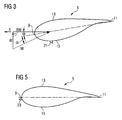
- the wind conditions at an airfoil are shown in Figure 3 .
- the figure shows the wind direction W of the ambient wind and the rotation direction R of the rotor blade 5.
- the chord line of the profile and the rotation direction include an angle ⁇ which is the pitch angle of the rotor blade.
- the pitch angle is set such that the rotor rotates with the optimum rotor speed and the power of the wind turbine is limited to a maximum power in a wind turbine with power regulation based on the pitch.
- Due to the rotation the rotor blade 5 experiences a relative wind which is indicated by arrow RW.
- the relative wind and the ambient wind sum up vectorially to the incident wind IW.
- the angle between the chord line and the direction of the incident wind IW is called the angle of attack ⁇ .
- angle of attack ⁇ In a pitch regulated wind turbine the angle of attack ⁇ will be reduced for reducing power output and increased for increasing power output of the wind turbine. In airfoil design the focus is usually on a high lift to drag ratio at angles of attack of about 2°.
- the lift and the drag at very high and very low angles of attack is less important when the airfoils are used for aeroplane design.
- the characteristics at a low angle of attack are important for the loads of the turbine. Such low angles of attack can result from power reduction at high wind speeds.
- the stall inducing device 21 will reduce the negative lift on the airfoil profile by inducing stall on the trailing edge side of the device 21. This is because behind the wedge-like geometry of the stall inducing device 21 a small recirculation region will appear. At a negative angle of attack ⁇ this region will tend to burst and hence trigger a larger stall on the upwind side 15 of the airfoil 5. On the other hand, when the angle of attack ⁇ is positive, i.e. the incident wind hits the blade on the upwind side 15, the stall inducing device 21 will have no substantial effect on the airflow so that the operation of the wind turbine rotor blade 1 is not negatively influenced under normal operation conditions.
- the measured lift coefficient C 1 and the measured drag coefficient C d for an inventive wind turbine rotor blade 1 according to Figure 2 are shown in Figure 4 in dependence on the angle of attack ⁇ .
- the lift coefficient C 1_ref and the drag coefficient C d_ref of a wind turbine blade having the profile shown in Figure 2 but without the stall inducing device 21 are also shown in the figure.
- the left side end and the right side end of the curves represent conditions where the airfoil stalls. Hence, both the minimum and the maximum lift are achieved just before the airfoil stalls.
- Figure 4 shows that at angles of attack of 3° and higher the lift coefficients C 1 , C 1_ref for the rotor blades with and without the stall inducing device 21 almost coincide.
- the influence of the stall inducing device 21 is, therefore, not severe.
- the same is seen on the drag coefficient C d .
- From about an angle of attack ⁇ of 5° upwards the drag coefficients C d , C d_ref of the blade with and without the stall inducing device almost coincide. Only below about 5° to 4° does the drag coefficient C d of the wind turbine rotor blade 1 with the stall inducing device 21 increase because of the stall on the upwind side 15 of the airfoil 5.
- the minimum lift coefficient C 1 for the inventive wind turbine rotor blade 1 is about -1.0.
- a wind turbine rotor blade without the stall inducing device 21 already reaches a negative lift coefficient C 1_ref at about - 1° and has a minimum lift coefficient of about -1.4°.
- the lift coefficient C 1 of the inventive wind turbine rotor blade 1 is always higher than the lift coefficient C 1_ref of a wind turbine rotor blade without the stall inducing device 21 at the upwind side 15. This would decrease both the fatigue and the extreme loads on the wind turbine for negative angles of attack ⁇ .
- a situation where a wind turbine blade 1 experiences negative lift on a part of the airfoil 5 while the other wind turbine rotor blades experience positive lift will not occur until a negative angle of attack ⁇ of -14° is reached.
- An operation at low angles of attack is therefore less prone to conditions which produce large yawing or tilting moments.
- Shifting the minimum lift coefficient of the airfoil 5 to higher lift coefficients C 1 therefore decreases both the fatigue and the extreme loads of the turbine.
- FIG. 5 shows the profile of the blade's airfoil portion 5.
- Elements of this embodiment which do not differ from the first embodiment are designated with the same reference numerals as in Figure 2 and will not be described again to avoid repetition.
- the difference of the embodiment shown in Figure 5 from the first embodiment as shown in Figure 2 lies in the location and the cross-section of the stall inducing device.
- the stall inducing device 23 is located close to the leading edge 9 of the airfoil profile.
- the stall inducing device 23 of the second embodiment has a cross-section which resembles an isosceles triangle. The location of the triangle is below 5% chord length as measured from the leading edge 9 and, in the present embodiment, at about 2% chord length.
- the present invention allows for releasing the restrictions on dimensioning the turbine structure. This means less heavy designs can be realised compared to those designs which take high asymmetric loads into account by dimensioning the structure.
Abstract
Description
- The present invention relates to a wind turbine rotor blade and to a pitch regulated wind turbine comprising a rotor with at least one rotor blade.
- There are two different ways of regulating the power output of a wind turbine, namely pitch regulation and stall regulation.
- In pitch regulated wind turbines the wind turbine power is regulated by setting an appropriate pitch angle for the rotor blades of the rotor. By setting the pitch angle, the machine can be operated with the optimum rotor speed in a wide range of wind speeds. However, wind turbines usually operate in a turbulent wind field. A pitch regulated wind turbine operating in such a turbulent wind field at high wind speed may experience negative lift on a part of the rotor blade's airfoil. In this case the wind load on the turbine blade will be opposite to the main wind direction. If this correlates with a positive lift load on the other two blades of a three bladed rotor very high yawing and tilting moments acting on the wind turbine structure can occur.
- The issue of the very high tilting and yawing moments has been addressed hitherto by dimensioning the structure of wind turbine rotor blades so as to sustain the occurring loads.
- In stall regulated wind turbines the limitation of power is regulated by setting an appropriate rotor speed. Setting the rotor speed is done by inducing a stall at the rotor blades. The pitch angles of the rotor blades are fixed in such machines. For stall regulated wind turbines it is known to use turbulators at the leading edge of a rotor blade's airfoil profile in order to reduce stall vibrations. Such turbulators are, for example, disclosed in
EP 0 954 701 B1 . - The occurrence of very high yawing and tilting moments is an issue of a pitch regulated wind turbine and not of a stall regulated wind turbine since rotor speed and pitch angle of the rotor blades at a given wind speed will differ according to the regulation mechanism used.
- It is therefore an objective of the present invention to provide a wind turbine rotor blade which is suitable for overcoming the above-mentioned issue in a pitch regulated wind turbine. It is a further objective of the present invention to provide an improved pitch regulated wind turbine.
- The first objective is solved by a wind turbine rotor blade according to claim 1. The second objective is solved by a pitch regulated wind turbine according to claim 8. The depending claims contain further developments of the invention.
- An inventive wind turbine rotor blade comprises an airfoil profile having an upwind side and a downwind side. At the upwind side of the airfoil profile a stall inducing device is located.
- As has already been mentioned in the introduction stall inducing devices on the leading edge or at the downwind side of a wind turbine rotor blade airfoil profile are already known from stall regulates wind turbines. In these cases the stall inducing devices are used to reduce the positive lift and thereby reduce the active power of a wind turbine. However, stall inducing devices on the upwind side of a wind turbine blade airfoil profile have different effects compared to the stall inducing devices at the leading edge or downwind side for power regulation in stall regulated wind turbines. By situating such stall inducing devices at the upwind side in pitch regulated wind turbines the maximum negative lift on the airfoil is reduced by disturbing the flow at the upwind side.
- The present invention is based on the following observation:
- A wind turbine operates in a turbulent wind field. This results in a different angle of attack of the relative wind at a given pitch angle as measured with respect to the chord of the profile. Different angles of attack, however, lead to different lifts on the airfoil. For usual operation conditions at moderate turbulence a pitch regulated turbine always operates in a linear part of the lift curve, i.e. the lift changes proportional to a change in the angle of attack. In some situations, however, a combination of rotor position and a strong shear in the wind field may result in an angle of attack outside this linear region. In these situations the loads on the turbine will be strongly related to the maximum lift and the minimum lift of the airfoil. Both the minimum and the maximum lift are achieved just before the airfoil stalls. In the situation with negative lift the flow separates on the upstream side of the airfoil. Therefore, by changing the absolute value of the minimum lift of an airfoil would decrease both the fatigue and the extreme loads on the turbine.
- A suitable stall inducing device can have a triangular cross-section. In particular, the cross-section may be the cross-section of a scalene triangle or of an isosceles triangle. In the case of a scalene triangle the stall inducing device is advantageously located between 5% chord length and 30% chord length of the profile, preferably between 10% chord length and 20% chord length. In case the stall inducing device has the cross-section of an isosceles triangle it is advantageously located close to the leading edge, i.e. at below 5% chord length of the profile, in particular between 2% chord length and 5% chord length.
- The stall inducing device of the inventive wind turbine rotor blade has the advantage of reducing the absolute value of the maximum negative lift but does not, to any appreciable degree, influence the operation characteristics of the blade profile in normal operation conditions. On the other hand, under operating conditions that can lead to a highly asymmetric loading it has a profound and positive influence on the loads.
- An inventive pitch regulated wind turbine comprises a rotor with at least one inventive wind turbine rotor blade. In such a wind turbine the yawing and tilting moments on the wind turbine structure at high wind speeds can be reduced compared to a wind turbine without an inventive rotor blade.
- Further features, properties and advantages of the present invention will become clear from the following description of embodiments in conjunction with the accompanying drawings.
-
Figure 1 shows a wind turbine rotor blade in a plain view on the plane defined by the blade's span and the blade chord. -
Figure 2 shows a chord-wise section through the airfoil portion of the rotor blade according to a first embodiment of the invention. -
Figure 3 shows the incident flow at a wind turbine rotor blade. -
Figure 4 shows measured values for the lift and the drag on an inventive wind turbine rotor blade compared to a conventional rotor blade. -
Figure 5 shows a chord-wise section through the airfoil portion of a rotor blade according to a second embodiment of the invention. -
Figure 1 shows a wind turbine blade 1 as it is usually used in a three-blade rotor. However, the present invention shall not be limited to blades for three-blade rotors. In fact, it may also be implemented in other rotors like one-blade rotors or two-blade rotors, or in rotors with more than three blades. - The rotor blade 1 shown in
Figure 1 comprises aroot portion 3 with a cylindrical profile and atip 2 which forms the outermost part of the blade 1. The cylindrical profile of theroot portion 3 serves to fix the blade 1 to a bearing of a rotor hub (not shown). The rotor blade 1 further comprises a so-called shoulder 7 which is defined as being the location of the blades maximum profile depth, i.e. its maximum chord length. Theairfoil 5 extends along the so-called span (dash dotted line inFig. 1 ) between theroot portion 3 and thetip 2. - A chord-wise cross-section through the rotor blade's
airfoil 5 is shown inFigure 2 . The aerodynamic profile of theairfoil 5 shown inFigure 2 comprises aconvex suction side 13, which forms the downwind side of the profile, and a lessconvex pressure side 15, which forms the upwind side of the profile. The dash-dotted line extending from the blade's leadingedge 9 to itstrailing edge 11 shows the chord of the profile which is perpendicular to the span. Although thepressure side 15 comprises aconvex section 17 and aconcave section 19 inFigure 2 , it may be implemented without a concave section at all as long as thesuction side 13 is more convex than thepressure side 15. - A
stall inducing device 21 is located at thepressure side 15 at about 20% of the chord length as measured from the leadingedge 9 of the profile of theairfoil 5. Thestall inducing device 21 has a cross-section which resembles a scalene triangle and extends span-wise continuously or intermittently over a section of theairfoil 5. - The wind conditions at an airfoil are shown in
Figure 3 . The figure shows the wind direction W of the ambient wind and the rotation direction R of therotor blade 5. As can be seen from the figure, the chord line of the profile and the rotation direction include an angle θ which is the pitch angle of the rotor blade. The pitch angle is set such that the rotor rotates with the optimum rotor speed and the power of the wind turbine is limited to a maximum power in a wind turbine with power regulation based on the pitch. Due to the rotation therotor blade 5 experiences a relative wind which is indicated by arrow RW. The relative wind and the ambient wind sum up vectorially to the incident wind IW. The angle between the chord line and the direction of the incident wind IW is called the angle of attack α. - In a pitch regulated wind turbine the angle of attack α will be reduced for reducing power output and increased for increasing power output of the wind turbine. In airfoil design the focus is usually on a high lift to drag ratio at angles of attack of about 2°.
- The lift and the drag at very high and very low angles of attack is less important when the airfoils are used for aeroplane design. For a wind turbine, however, the characteristics at a low angle of attack are important for the loads of the turbine. Such low angles of attack can result from power reduction at high wind speeds.
- Since a pitch regulated wind turbine operates in a turbulent wind field at high wind speeds a situation may arise when the pitch angle θ is set such that the angle of attack is close to 0° in which the angle of attack fluctuates around 0°. Such fluctuations may result in an angle of attack α which is negative, i.e. the wind attacks the
airfoil 5 from thedownwind side 13 rather than from theupwind side 15. In this case the rotor blade 1 will experience negative lift on a part of theairfoil 5 and the wind loads on the wind turbine blade 1 will be opposite to the main wind direction. - If this correlates with positive lift loads on the other two blades the yawing and tilting moments on the structure of the wind turbine can become very high in a conventional wind turbine rotor blade.
- In the inventive wind turbine rotor blade 1, however, the
stall inducing device 21 will reduce the negative lift on the airfoil profile by inducing stall on the trailing edge side of thedevice 21. This is because behind the wedge-like geometry of the stall inducing device 21 a small recirculation region will appear. At a negative angle of attack α this region will tend to burst and hence trigger a larger stall on theupwind side 15 of theairfoil 5. On the other hand, when the angle of attack α is positive, i.e. the incident wind hits the blade on theupwind side 15, thestall inducing device 21 will have no substantial effect on the airflow so that the operation of the wind turbine rotor blade 1 is not negatively influenced under normal operation conditions. - The measured lift coefficient C1 and the measured drag coefficient Cd for an inventive wind turbine rotor blade 1 according to
Figure 2 are shown inFigure 4 in dependence on the angle of attack α. In order to be able to compare the inventive wind turbine blade 1 to a conventional wind turbine blade the lift coefficient C1_ref and the drag coefficient Cd_ref of a wind turbine blade having the profile shown inFigure 2 but without thestall inducing device 21 are also shown in the figure. The left side end and the right side end of the curves represent conditions where the airfoil stalls. Hence, both the minimum and the maximum lift are achieved just before the airfoil stalls. -
Figure 4 shows that at angles of attack of 3° and higher the lift coefficients C1, C1_ref for the rotor blades with and without thestall inducing device 21 almost coincide. At normal operation conditions with a lift coefficient C1 of about 0.6 to 1.2 the influence of thestall inducing device 21 is, therefore, not severe. The same is seen on the drag coefficient Cd. From about an angle of attack α of 5° upwards the drag coefficients Cd, Cd_ref of the blade with and without the stall inducing device almost coincide. Only below about 5° to 4° does the drag coefficient Cd of the wind turbine rotor blade 1 with thestall inducing device 21 increase because of the stall on theupwind side 15 of theairfoil 5. - At angles of attack α below about +3° the lift coefficient C1 of the inventive wind turbine rotor blade 1 is almost unchanged over a range of about 10°. From about α =-7° the lift coefficient C1 then falls continuously with decreasing angles of attack α and becomes negative at about -14°. The minimum lift coefficient C1 for the inventive wind turbine rotor blade 1 is about -1.0. In contrast thereto, a wind turbine rotor blade without the
stall inducing device 21 already reaches a negative lift coefficient C1_ref at about - 1° and has a minimum lift coefficient of about -1.4°. Hence, for angles of attack α lower than about +3° the lift coefficient C1 of the inventive wind turbine rotor blade 1 is always higher than the lift coefficient C1_ref of a wind turbine rotor blade without thestall inducing device 21 at theupwind side 15. This would decrease both the fatigue and the extreme loads on the wind turbine for negative angles of attack α. As a consequence, a situation where a wind turbine blade 1 experiences negative lift on a part of theairfoil 5 while the other wind turbine rotor blades experience positive lift will not occur until a negative angle of attack α of -14° is reached. An operation at low angles of attack is therefore less prone to conditions which produce large yawing or tilting moments. - Shifting the minimum lift coefficient of the
airfoil 5 to higher lift coefficients C1 therefore decreases both the fatigue and the extreme loads of the turbine. - A second embodiment of the inventive wind turbine blade is shown in
Figure 5 which shows the profile of the blade'sairfoil portion 5. Elements of this embodiment which do not differ from the first embodiment are designated with the same reference numerals as inFigure 2 and will not be described again to avoid repetition. - The difference of the embodiment shown in
Figure 5 from the first embodiment as shown inFigure 2 lies in the location and the cross-section of the stall inducing device. In the second embodiment thestall inducing device 23 is located close to theleading edge 9 of the airfoil profile. Moreover, instead of having a cross-section which resembles a scalene triangle thestall inducing device 23 of the second embodiment has a cross-section which resembles an isosceles triangle. The location of the triangle is below 5% chord length as measured from theleading edge 9 and, in the present embodiment, at about 2% chord length. - Although two particular embodiments of the inventive wind turbine rotor blade have been described which resemble two extremes in cross-section and location of the
stall inducing devices - While in the state of the art the issue of occasionally high asymmetric loads on the wind turbine structure has generally been addressed by dimensioning the structure so as to sustain the highest predictive loads, the present invention allows for releasing the restrictions on dimensioning the turbine structure. This means less heavy designs can be realised compared to those designs which take high asymmetric loads into account by dimensioning the structure.
Claims (8)
- A wind turbine rotor blade (1) with an airfoil profile (5) having an upwind side (15) and a downwind side (13),
characterised in
a stall inducing device (21) located at the upwind side (15) of the airfoil profile (5). - The wind turbine rotor blade (1) as claimed in claim 1,
characterised in that
the stall inducing device (21, 23) has a triangular cross-section. - The wind turbine rotor blade (1) as claimed in claim 2,
characterised in that
the stall inducing device (21) has the cross section of a scalene triangle. - The wind turbine rotor blade (1) as claimed in claim 3,
characterised in that
the stall inducing device (21) is located between 5% chord length and 30% chord length. - The wind turbine rotor blade (1) as claimed in claim 2,
characterised in that
the stall inducing device (23) has the cross section of an isosceles triangle. - The wind turbine rotor blade (1) as claimed in claim 5,
characterised in that
the stall inducing device (23) is located close to the leading edge (9) of the airfoil profile (5). - The wind turbine rotor blade (1) as claimed in claim 6,
characterised in that
the stall inducing device (23) is located between 2% chord length and 5% chord length. - A pitch regulated wind turbine comprising a rotor with at least one wind turbine rotor blade (1) according to any of the preceding claims.
Priority Applications (7)
| Application Number | Priority Date | Filing Date | Title |
|---|---|---|---|
| EP07014329A EP2017467B1 (en) | 2007-07-20 | 2007-07-20 | Wind turbine rotor blade and pitch regulated wind turbine |
| AT07014329T ATE461365T1 (en) | 2007-07-20 | 2007-07-20 | WIND TURBINE ROTOR BLADE AND TILT CONTROLLED WIND TURBINE |
| ES07014329T ES2339883T3 (en) | 2007-07-20 | 2007-07-20 | ROTOR SHOVEL OF WIND TURBINE AND WIND TURBINE WITH STEP REGULATION. |
| DK07014329.2T DK2017467T3 (en) | 2007-07-20 | 2007-07-20 | Wind turbine blade and wind turbine with pitch control |
| DE602007005364T DE602007005364D1 (en) | 2007-07-20 | 2007-07-20 | Wind turbine rotor blade and pitch-controlled wind turbine |
| US12/218,727 US8602739B2 (en) | 2007-07-20 | 2008-07-17 | Wind turbine rotor blade and pitch regulated wind turbine |
| CN2008101714107A CN101403368B (en) | 2007-07-20 | 2008-07-21 | Wind turbine rotor blade and pitch regulated wind turbine |
Applications Claiming Priority (1)
| Application Number | Priority Date | Filing Date | Title |
|---|---|---|---|
| EP07014329A EP2017467B1 (en) | 2007-07-20 | 2007-07-20 | Wind turbine rotor blade and pitch regulated wind turbine |
Publications (2)
| Publication Number | Publication Date |
|---|---|
| EP2017467A1 true EP2017467A1 (en) | 2009-01-21 |
| EP2017467B1 EP2017467B1 (en) | 2010-03-17 |
Family
ID=40032812
Family Applications (1)
| Application Number | Title | Priority Date | Filing Date |
|---|---|---|---|
| EP07014329A Not-in-force EP2017467B1 (en) | 2007-07-20 | 2007-07-20 | Wind turbine rotor blade and pitch regulated wind turbine |
Country Status (7)
| Country | Link |
|---|---|
| US (1) | US8602739B2 (en) |
| EP (1) | EP2017467B1 (en) |
| CN (1) | CN101403368B (en) |
| AT (1) | ATE461365T1 (en) |
| DE (1) | DE602007005364D1 (en) |
| DK (1) | DK2017467T3 (en) |
| ES (1) | ES2339883T3 (en) |
Cited By (3)
| Publication number | Priority date | Publication date | Assignee | Title |
|---|---|---|---|---|
| CN101539119A (en) * | 2008-03-07 | 2009-09-23 | 歌美飒创新技术公司 | A wind turbine blade |
| CN103047181A (en) * | 2012-12-06 | 2013-04-17 | 大连理工大学 | High-flow axial flow fan with high-aspect-ratio blades |
| WO2014060446A1 (en) * | 2012-10-16 | 2014-04-24 | Wobben Properties Gmbh | Wind turbine |
Families Citing this family (13)
| Publication number | Priority date | Publication date | Assignee | Title |
|---|---|---|---|---|
| CN102264406B (en) | 2008-12-31 | 2015-01-14 | 凯希特许有限公司 | Sleeves, manifolds, systems, and methods for applying reduced pressure to subcutaneous tissue site |
| CN101813070B (en) * | 2010-04-13 | 2012-07-25 | 南京航空航天大学 | Vane airfoil profile of low power wind driven generator |
| US8251657B2 (en) | 2011-01-06 | 2012-08-28 | Siemens Aktiengesellschaft | Load mitigation device for wind turbine blades |
| CN102094769B (en) * | 2011-02-24 | 2012-09-26 | 西北工业大学 | Wind machine blade airfoil profile capable of controlling flow stalling through standing vortex |
| US9689374B2 (en) | 2013-10-09 | 2017-06-27 | Siemens Aktiengesellschaft | Method and apparatus for reduction of fatigue and gust loads on wind turbine blades |
| US20150361951A1 (en) | 2014-06-17 | 2015-12-17 | Siemens Energy, Inc. | Pressure side stall strip for wind turbine blade |
| DK178874B1 (en) * | 2015-08-19 | 2017-04-18 | Envision Energy (Jiangsu) Co Ltd | Wind turbine blade with tripping device and method thereof |
| ES2855987T3 (en) | 2015-09-03 | 2021-09-27 | Siemens Gamesa Renewable Energy As | Wind Turbine Blade with Trailing Edge Flange |
| US10400744B2 (en) * | 2016-04-28 | 2019-09-03 | General Electric Company | Wind turbine blade with noise reducing micro boundary layer energizers |
| EP3330661B1 (en) | 2016-12-01 | 2019-06-05 | BENELLI ARMI S.p.A. | Portable firearm with quick coupling removable stock |
| FR3077802B1 (en) * | 2018-02-15 | 2020-09-11 | Airbus Helicopters | METHOD OF DETERMINING AN INITIAL ATTACK EDGE CIRCLE OF AERODYNAMIC PROFILES OF A BLADE AND IMPROVEMENT OF THE BLADE IN ORDER TO INCREASE ITS NEGATIVE INCIDENCE OF STALL |
| FR3077803B1 (en) * | 2018-02-15 | 2020-07-31 | Airbus Helicopters | METHOD OF IMPROVING A BLADE IN ORDER TO INCREASE ITS NEGATIVE INCIDENCE OF STALL |
| US10920742B2 (en) * | 2018-07-26 | 2021-02-16 | Institute of Nuclear Energy Research, Atomic Energy Council, Executive Yuan, R.O.C. | Noise-reduction device for wind turbine and the wind turbine applied thereof |
Citations (7)
| Publication number | Priority date | Publication date | Assignee | Title |
|---|---|---|---|---|
| EP0947693A2 (en) | 1998-03-31 | 1999-10-06 | Tacke Windenergie GmbH | Wind turbine blade profile |
| WO2001016482A1 (en) | 1999-09-01 | 2001-03-08 | Stichting Energieonderzoek Centrum Nederland | Blade for a wind turbine |
| EP0954701B1 (en) | 1996-11-18 | 2001-05-30 | Lm Glasfiber A/S | The use of a turbulator for damping stall vibrations in the blades of a wind turbine |
| WO2004099608A1 (en) | 2003-05-05 | 2004-11-18 | Lm Glasfiber A/S | Wind turbine blade with lift-regulating means |
| WO2006122547A1 (en) | 2005-05-17 | 2006-11-23 | Vestas Wind Systems A/S | A pitch controlled wind turbine blade, a wind turbine and use hereof |
| US20070110585A1 (en) | 2005-11-17 | 2007-05-17 | General Electric Company | Rotor blade for a wind turbine having aerodynamic feature elements |
| WO2007114698A2 (en) | 2006-04-02 | 2007-10-11 | Gustave Paul Corten | Wind turbine with slender blade |
Family Cites Families (1)
| Publication number | Priority date | Publication date | Assignee | Title |
|---|---|---|---|---|
| GB9419712D0 (en) * | 1994-09-30 | 1994-11-16 | Rolls Royce Plc | A turbomachine aerofoil and a method of production |
-
2007
- 2007-07-20 ES ES07014329T patent/ES2339883T3/en active Active
- 2007-07-20 DE DE602007005364T patent/DE602007005364D1/en active Active
- 2007-07-20 AT AT07014329T patent/ATE461365T1/en not_active IP Right Cessation
- 2007-07-20 EP EP07014329A patent/EP2017467B1/en not_active Not-in-force
- 2007-07-20 DK DK07014329.2T patent/DK2017467T3/en active
-
2008
- 2008-07-17 US US12/218,727 patent/US8602739B2/en not_active Expired - Fee Related
- 2008-07-21 CN CN2008101714107A patent/CN101403368B/en not_active Expired - Fee Related
Patent Citations (7)
| Publication number | Priority date | Publication date | Assignee | Title |
|---|---|---|---|---|
| EP0954701B1 (en) | 1996-11-18 | 2001-05-30 | Lm Glasfiber A/S | The use of a turbulator for damping stall vibrations in the blades of a wind turbine |
| EP0947693A2 (en) | 1998-03-31 | 1999-10-06 | Tacke Windenergie GmbH | Wind turbine blade profile |
| WO2001016482A1 (en) | 1999-09-01 | 2001-03-08 | Stichting Energieonderzoek Centrum Nederland | Blade for a wind turbine |
| WO2004099608A1 (en) | 2003-05-05 | 2004-11-18 | Lm Glasfiber A/S | Wind turbine blade with lift-regulating means |
| WO2006122547A1 (en) | 2005-05-17 | 2006-11-23 | Vestas Wind Systems A/S | A pitch controlled wind turbine blade, a wind turbine and use hereof |
| US20070110585A1 (en) | 2005-11-17 | 2007-05-17 | General Electric Company | Rotor blade for a wind turbine having aerodynamic feature elements |
| WO2007114698A2 (en) | 2006-04-02 | 2007-10-11 | Gustave Paul Corten | Wind turbine with slender blade |
Cited By (6)
| Publication number | Priority date | Publication date | Assignee | Title |
|---|---|---|---|---|
| CN101539119A (en) * | 2008-03-07 | 2009-09-23 | 歌美飒创新技术公司 | A wind turbine blade |
| EP2098721A3 (en) * | 2008-03-07 | 2011-05-04 | Gamesa Innovation & Technology, S.L. | A wind turbine blade |
| WO2014060446A1 (en) * | 2012-10-16 | 2014-04-24 | Wobben Properties Gmbh | Wind turbine |
| RU2601017C1 (en) * | 2012-10-16 | 2016-10-27 | Воббен Пропертиз Гмбх | Wind turbine |
| CN103047181A (en) * | 2012-12-06 | 2013-04-17 | 大连理工大学 | High-flow axial flow fan with high-aspect-ratio blades |
| CN103047181B (en) * | 2012-12-06 | 2015-12-09 | 大连理工大学 | A kind of large discharge high aspect ratio blade axial-flow fan |
Also Published As
| Publication number | Publication date |
|---|---|
| DK2017467T3 (en) | 2010-06-28 |
| ATE461365T1 (en) | 2010-04-15 |
| ES2339883T3 (en) | 2010-05-26 |
| DE602007005364D1 (en) | 2010-04-29 |
| CN101403368B (en) | 2012-10-10 |
| CN101403368A (en) | 2009-04-08 |
| EP2017467B1 (en) | 2010-03-17 |
| US20090028718A1 (en) | 2009-01-29 |
| US8602739B2 (en) | 2013-12-10 |
Similar Documents
| Publication | Publication Date | Title |
|---|---|---|
| US8602739B2 (en) | Wind turbine rotor blade and pitch regulated wind turbine | |
| EP2004989B1 (en) | Wind turbine rotor blade | |
| US8834130B2 (en) | Wind turbine blade with an auxiliary airfoil | |
| US7914259B2 (en) | Wind turbine blades with vortex generators | |
| EP2940293A1 (en) | Aerodynamic device for a rotor blade of a wind turbine | |
| EP1944505A1 (en) | Wind turbine rotor blade with vortex generators | |
| US20160177914A1 (en) | Rotor blade with vortex generators | |
| EP2957766B1 (en) | Pressure side stall strip for wind turbine blade | |
| EP3453872B1 (en) | Methods for mitigating noise during high wind speed conditions of wind turbines | |
| US8100661B2 (en) | Wind turbine rotor blade and wind turbine rotor | |
| CN111742137A (en) | Rotor blade with a wind deflector for a wind energy installation | |
| CN107923364B (en) | Rotor blade shaped to enhance wake diffusion | |
| US11028823B2 (en) | Wind turbine blade with tip end serrations | |
| KR20130069812A (en) | Wind turbine blade, wind power generating device comprising same, and wind turbine blade design method | |
| US11852118B2 (en) | Wind turbine | |
| WO2018145715A1 (en) | Method and system for controlling a wind turbine | |
| EP3580453B1 (en) | Method and system for controlling a wind turbine | |
| US11454206B2 (en) | Rotor blade for a wind turbine | |
| WO2022002333A1 (en) | A wind turbine | |
| CN113891991A (en) | Rotor blade and wind power plant |
Legal Events
| Date | Code | Title | Description |
|---|---|---|---|
| PUAI | Public reference made under article 153(3) epc to a published international application that has entered the european phase |
Free format text: ORIGINAL CODE: 0009012 |
|
| AK | Designated contracting states |
Kind code of ref document: A1 Designated state(s): AT BE BG CH CY CZ DE DK EE ES FI FR GB GR HU IE IS IT LI LT LU LV MC MT NL PL PT RO SE SI SK TR |
|
| AX | Request for extension of the european patent |
Extension state: AL BA HR MK RS |
|
| 17P | Request for examination filed |
Effective date: 20090428 |
|
| R17P | Request for examination filed (corrected) |
Effective date: 20090420 |
|
| 17Q | First examination report despatched |
Effective date: 20090630 |
|
| AKX | Designation fees paid |
Designated state(s): AT BE BG CH CY CZ DE DK EE ES FI FR GB GR HU IE IS IT LI LT LU LV MC MT NL PL PT RO SE SI SK TR |
|
| GRAP | Despatch of communication of intention to grant a patent |
Free format text: ORIGINAL CODE: EPIDOSNIGR1 |
|
| GRAS | Grant fee paid |
Free format text: ORIGINAL CODE: EPIDOSNIGR3 |
|
| GRAA | (expected) grant |
Free format text: ORIGINAL CODE: 0009210 |
|
| AK | Designated contracting states |
Kind code of ref document: B1 Designated state(s): AT BE BG CH CY CZ DE DK EE ES FI FR GB GR HU IE IS IT LI LT LU LV MC MT NL PL PT RO SE SI SK TR |
|
| REG | Reference to a national code |
Ref country code: GB Ref legal event code: FG4D |
|
| REG | Reference to a national code |
Ref country code: CH Ref legal event code: EP |
|
| REG | Reference to a national code |
Ref country code: IE Ref legal event code: FG4D |
|
| REF | Corresponds to: |
Ref document number: 602007005364 Country of ref document: DE Date of ref document: 20100429 Kind code of ref document: P |
|
| REG | Reference to a national code |
Ref country code: SE Ref legal event code: TRGR |
|
| REG | Reference to a national code |
Ref country code: ES Ref legal event code: FG2A Ref document number: 2339883 Country of ref document: ES Kind code of ref document: T3 |
|
| REG | Reference to a national code |
Ref country code: DK Ref legal event code: T3 |
|
| REG | Reference to a national code |
Ref country code: NL Ref legal event code: VDEP Effective date: 20100317 |
|
| PG25 | Lapsed in a contracting state [announced via postgrant information from national office to epo] |
Ref country code: LT Free format text: LAPSE BECAUSE OF FAILURE TO SUBMIT A TRANSLATION OF THE DESCRIPTION OR TO PAY THE FEE WITHIN THE PRESCRIBED TIME-LIMIT Effective date: 20100317 |
|
| LTIE | Lt: invalidation of european patent or patent extension |
Effective date: 20100317 |
|
| PG25 | Lapsed in a contracting state [announced via postgrant information from national office to epo] |
Ref country code: AT Free format text: LAPSE BECAUSE OF FAILURE TO SUBMIT A TRANSLATION OF THE DESCRIPTION OR TO PAY THE FEE WITHIN THE PRESCRIBED TIME-LIMIT Effective date: 20100317 Ref country code: FI Free format text: LAPSE BECAUSE OF FAILURE TO SUBMIT A TRANSLATION OF THE DESCRIPTION OR TO PAY THE FEE WITHIN THE PRESCRIBED TIME-LIMIT Effective date: 20100317 Ref country code: LV Free format text: LAPSE BECAUSE OF FAILURE TO SUBMIT A TRANSLATION OF THE DESCRIPTION OR TO PAY THE FEE WITHIN THE PRESCRIBED TIME-LIMIT Effective date: 20100317 Ref country code: PL Free format text: LAPSE BECAUSE OF FAILURE TO SUBMIT A TRANSLATION OF THE DESCRIPTION OR TO PAY THE FEE WITHIN THE PRESCRIBED TIME-LIMIT Effective date: 20100317 Ref country code: SI Free format text: LAPSE BECAUSE OF FAILURE TO SUBMIT A TRANSLATION OF THE DESCRIPTION OR TO PAY THE FEE WITHIN THE PRESCRIBED TIME-LIMIT Effective date: 20100317 |
|
| PG25 | Lapsed in a contracting state [announced via postgrant information from national office to epo] |
Ref country code: RO Free format text: LAPSE BECAUSE OF FAILURE TO SUBMIT A TRANSLATION OF THE DESCRIPTION OR TO PAY THE FEE WITHIN THE PRESCRIBED TIME-LIMIT Effective date: 20100317 Ref country code: NL Free format text: LAPSE BECAUSE OF FAILURE TO SUBMIT A TRANSLATION OF THE DESCRIPTION OR TO PAY THE FEE WITHIN THE PRESCRIBED TIME-LIMIT Effective date: 20100317 Ref country code: GR Free format text: LAPSE BECAUSE OF FAILURE TO SUBMIT A TRANSLATION OF THE DESCRIPTION OR TO PAY THE FEE WITHIN THE PRESCRIBED TIME-LIMIT Effective date: 20100618 Ref country code: EE Free format text: LAPSE BECAUSE OF FAILURE TO SUBMIT A TRANSLATION OF THE DESCRIPTION OR TO PAY THE FEE WITHIN THE PRESCRIBED TIME-LIMIT Effective date: 20100317 Ref country code: CY Free format text: LAPSE BECAUSE OF FAILURE TO SUBMIT A TRANSLATION OF THE DESCRIPTION OR TO PAY THE FEE WITHIN THE PRESCRIBED TIME-LIMIT Effective date: 20100317 Ref country code: BE Free format text: LAPSE BECAUSE OF FAILURE TO SUBMIT A TRANSLATION OF THE DESCRIPTION OR TO PAY THE FEE WITHIN THE PRESCRIBED TIME-LIMIT Effective date: 20100317 |
|
| PG25 | Lapsed in a contracting state [announced via postgrant information from national office to epo] |
Ref country code: BG Free format text: LAPSE BECAUSE OF FAILURE TO SUBMIT A TRANSLATION OF THE DESCRIPTION OR TO PAY THE FEE WITHIN THE PRESCRIBED TIME-LIMIT Effective date: 20100617 Ref country code: SK Free format text: LAPSE BECAUSE OF FAILURE TO SUBMIT A TRANSLATION OF THE DESCRIPTION OR TO PAY THE FEE WITHIN THE PRESCRIBED TIME-LIMIT Effective date: 20100317 Ref country code: IS Free format text: LAPSE BECAUSE OF FAILURE TO SUBMIT A TRANSLATION OF THE DESCRIPTION OR TO PAY THE FEE WITHIN THE PRESCRIBED TIME-LIMIT Effective date: 20100717 Ref country code: CZ Free format text: LAPSE BECAUSE OF FAILURE TO SUBMIT A TRANSLATION OF THE DESCRIPTION OR TO PAY THE FEE WITHIN THE PRESCRIBED TIME-LIMIT Effective date: 20100317 |
|
| PLBE | No opposition filed within time limit |
Free format text: ORIGINAL CODE: 0009261 |
|
| STAA | Information on the status of an ep patent application or granted ep patent |
Free format text: STATUS: NO OPPOSITION FILED WITHIN TIME LIMIT |
|
| PG25 | Lapsed in a contracting state [announced via postgrant information from national office to epo] |
Ref country code: PT Free format text: LAPSE BECAUSE OF FAILURE TO SUBMIT A TRANSLATION OF THE DESCRIPTION OR TO PAY THE FEE WITHIN THE PRESCRIBED TIME-LIMIT Effective date: 20100719 |
|
| 26N | No opposition filed |
Effective date: 20101220 |
|
| PG25 | Lapsed in a contracting state [announced via postgrant information from national office to epo] |
Ref country code: MC Free format text: LAPSE BECAUSE OF NON-PAYMENT OF DUE FEES Effective date: 20100731 |
|
| PG25 | Lapsed in a contracting state [announced via postgrant information from national office to epo] |
Ref country code: IT Free format text: LAPSE BECAUSE OF FAILURE TO SUBMIT A TRANSLATION OF THE DESCRIPTION OR TO PAY THE FEE WITHIN THE PRESCRIBED TIME-LIMIT Effective date: 20100317 |
|
| PG25 | Lapsed in a contracting state [announced via postgrant information from national office to epo] |
Ref country code: IE Free format text: LAPSE BECAUSE OF NON-PAYMENT OF DUE FEES Effective date: 20100720 |
|
| PG25 | Lapsed in a contracting state [announced via postgrant information from national office to epo] |
Ref country code: MT Free format text: LAPSE BECAUSE OF FAILURE TO SUBMIT A TRANSLATION OF THE DESCRIPTION OR TO PAY THE FEE WITHIN THE PRESCRIBED TIME-LIMIT Effective date: 20100317 |
|
| REG | Reference to a national code |
Ref country code: CH Ref legal event code: PL |
|
| PG25 | Lapsed in a contracting state [announced via postgrant information from national office to epo] |
Ref country code: CH Free format text: LAPSE BECAUSE OF NON-PAYMENT OF DUE FEES Effective date: 20110731 Ref country code: LI Free format text: LAPSE BECAUSE OF NON-PAYMENT OF DUE FEES Effective date: 20110731 |
|
| PG25 | Lapsed in a contracting state [announced via postgrant information from national office to epo] |
Ref country code: HU Free format text: LAPSE BECAUSE OF FAILURE TO SUBMIT A TRANSLATION OF THE DESCRIPTION OR TO PAY THE FEE WITHIN THE PRESCRIBED TIME-LIMIT Effective date: 20100918 Ref country code: LU Free format text: LAPSE BECAUSE OF NON-PAYMENT OF DUE FEES Effective date: 20100720 |
|
| PGFP | Annual fee paid to national office [announced via postgrant information from national office to epo] |
Ref country code: DE Payment date: 20150918 Year of fee payment: 9 |
|
| REG | Reference to a national code |
Ref country code: FR Ref legal event code: PLFP Year of fee payment: 10 |
|
| PGFP | Annual fee paid to national office [announced via postgrant information from national office to epo] |
Ref country code: TR Payment date: 20160623 Year of fee payment: 10 |
|
| PGFP | Annual fee paid to national office [announced via postgrant information from national office to epo] |
Ref country code: GB Payment date: 20160713 Year of fee payment: 10 Ref country code: DK Payment date: 20160720 Year of fee payment: 10 |
|
| PGFP | Annual fee paid to national office [announced via postgrant information from national office to epo] |
Ref country code: SE Payment date: 20160712 Year of fee payment: 10 Ref country code: FR Payment date: 20160725 Year of fee payment: 10 |
|
| PGFP | Annual fee paid to national office [announced via postgrant information from national office to epo] |
Ref country code: ES Payment date: 20160829 Year of fee payment: 10 |
|
| REG | Reference to a national code |
Ref country code: DE Ref legal event code: R119 Ref document number: 602007005364 Country of ref document: DE |
|
| PG25 | Lapsed in a contracting state [announced via postgrant information from national office to epo] |
Ref country code: DE Free format text: LAPSE BECAUSE OF NON-PAYMENT OF DUE FEES Effective date: 20170201 |
|
| REG | Reference to a national code |
Ref country code: DK Ref legal event code: EBP Effective date: 20170731 |
|
| REG | Reference to a national code |
Ref country code: SE Ref legal event code: EUG |
|
| GBPC | Gb: european patent ceased through non-payment of renewal fee |
Effective date: 20170720 |
|
| REG | Reference to a national code |
Ref country code: FR Ref legal event code: ST Effective date: 20180330 |
|
| PG25 | Lapsed in a contracting state [announced via postgrant information from national office to epo] |
Ref country code: GB Free format text: LAPSE BECAUSE OF NON-PAYMENT OF DUE FEES Effective date: 20170720 Ref country code: SE Free format text: LAPSE BECAUSE OF NON-PAYMENT OF DUE FEES Effective date: 20170721 |
|
| PG25 | Lapsed in a contracting state [announced via postgrant information from national office to epo] |
Ref country code: FR Free format text: LAPSE BECAUSE OF NON-PAYMENT OF DUE FEES Effective date: 20170731 |
|
| PG25 | Lapsed in a contracting state [announced via postgrant information from national office to epo] |
Ref country code: DK Free format text: LAPSE BECAUSE OF NON-PAYMENT OF DUE FEES Effective date: 20170731 |
|
| REG | Reference to a national code |
Ref country code: ES Ref legal event code: FD2A Effective date: 20181106 |
|
| PG25 | Lapsed in a contracting state [announced via postgrant information from national office to epo] |
Ref country code: ES Free format text: LAPSE BECAUSE OF NON-PAYMENT OF DUE FEES Effective date: 20170721 |
|
| PG25 | Lapsed in a contracting state [announced via postgrant information from national office to epo] |
Ref country code: TR Free format text: LAPSE BECAUSE OF NON-PAYMENT OF DUE FEES Effective date: 20170720 |