EP2004990B1 - Pale de rotor d'un dispositif d'énergie éolienne - Google Patents
Pale de rotor d'un dispositif d'énergie éolienne Download PDFInfo
- Publication number
- EP2004990B1 EP2004990B1 EP07723681.8A EP07723681A EP2004990B1 EP 2004990 B1 EP2004990 B1 EP 2004990B1 EP 07723681 A EP07723681 A EP 07723681A EP 2004990 B1 EP2004990 B1 EP 2004990B1
- Authority
- EP
- European Patent Office
- Prior art keywords
- rotor blade
- attached device
- profile
- attachment device
- profiles
- Prior art date
- Legal status (The legal status is an assumption and is not a legal conclusion. Google has not performed a legal analysis and makes no representation as to the accuracy of the status listed.)
- Revoked
Links
- 239000000853 adhesive Substances 0.000 claims description 6
- 230000001070 adhesive effect Effects 0.000 claims description 6
- 238000000034 method Methods 0.000 claims description 3
- 238000004519 manufacturing process Methods 0.000 description 8
- 238000010276 construction Methods 0.000 description 5
- 230000007423 decrease Effects 0.000 description 3
- 239000011152 fibreglass Substances 0.000 description 3
- 230000002441 reversible effect Effects 0.000 description 3
- 238000000926 separation method Methods 0.000 description 3
- 230000007704 transition Effects 0.000 description 3
- 238000011161 development Methods 0.000 description 2
- 230000002349 favourable effect Effects 0.000 description 2
- 206010024229 Leprosy Diseases 0.000 description 1
- 230000009286 beneficial effect Effects 0.000 description 1
- 238000004364 calculation method Methods 0.000 description 1
- 238000012938 design process Methods 0.000 description 1
- 238000006073 displacement reaction Methods 0.000 description 1
- 239000004744 fabric Substances 0.000 description 1
- 239000000835 fiber Substances 0.000 description 1
- 239000000463 material Substances 0.000 description 1
- 230000002093 peripheral effect Effects 0.000 description 1
- 230000000284 resting effect Effects 0.000 description 1
- 239000007921 spray Substances 0.000 description 1
- XLYOFNOQVPJJNP-UHFFFAOYSA-N water Substances O XLYOFNOQVPJJNP-UHFFFAOYSA-N 0.000 description 1
Images


Classifications
-
- F—MECHANICAL ENGINEERING; LIGHTING; HEATING; WEAPONS; BLASTING
- F03—MACHINES OR ENGINES FOR LIQUIDS; WIND, SPRING, OR WEIGHT MOTORS; PRODUCING MECHANICAL POWER OR A REACTIVE PROPULSIVE THRUST, NOT OTHERWISE PROVIDED FOR
- F03D—WIND MOTORS
- F03D1/00—Wind motors with rotation axis substantially parallel to the air flow entering the rotor
- F03D1/06—Rotors
- F03D1/0608—Rotors characterised by their aerodynamic shape
- F03D1/0633—Rotors characterised by their aerodynamic shape of the blades
- F03D1/0641—Rotors characterised by their aerodynamic shape of the blades of the section profile of the blades, i.e. aerofoil profile
-
- F—MECHANICAL ENGINEERING; LIGHTING; HEATING; WEAPONS; BLASTING
- F05—INDEXING SCHEMES RELATING TO ENGINES OR PUMPS IN VARIOUS SUBCLASSES OF CLASSES F01-F04
- F05B—INDEXING SCHEME RELATING TO WIND, SPRING, WEIGHT, INERTIA OR LIKE MOTORS, TO MACHINES OR ENGINES FOR LIQUIDS COVERED BY SUBCLASSES F03B, F03D AND F03G
- F05B2240/00—Components
- F05B2240/20—Rotors
- F05B2240/30—Characteristics of rotor blades, i.e. of any element transforming dynamic fluid energy to or from rotational energy and being attached to a rotor
- F05B2240/301—Cross-section characteristics
-
- F—MECHANICAL ENGINEERING; LIGHTING; HEATING; WEAPONS; BLASTING
- F05—INDEXING SCHEMES RELATING TO ENGINES OR PUMPS IN VARIOUS SUBCLASSES OF CLASSES F01-F04
- F05B—INDEXING SCHEME RELATING TO WIND, SPRING, WEIGHT, INERTIA OR LIKE MOTORS, TO MACHINES OR ENGINES FOR LIQUIDS COVERED BY SUBCLASSES F03B, F03D AND F03G
- F05B2240/00—Components
- F05B2240/20—Rotors
- F05B2240/30—Characteristics of rotor blades, i.e. of any element transforming dynamic fluid energy to or from rotational energy and being attached to a rotor
- F05B2240/31—Characteristics of rotor blades, i.e. of any element transforming dynamic fluid energy to or from rotational energy and being attached to a rotor of changeable form or shape
-
- Y—GENERAL TAGGING OF NEW TECHNOLOGICAL DEVELOPMENTS; GENERAL TAGGING OF CROSS-SECTIONAL TECHNOLOGIES SPANNING OVER SEVERAL SECTIONS OF THE IPC; TECHNICAL SUBJECTS COVERED BY FORMER USPC CROSS-REFERENCE ART COLLECTIONS [XRACs] AND DIGESTS
- Y02—TECHNOLOGIES OR APPLICATIONS FOR MITIGATION OR ADAPTATION AGAINST CLIMATE CHANGE
- Y02E—REDUCTION OF GREENHOUSE GAS [GHG] EMISSIONS, RELATED TO ENERGY GENERATION, TRANSMISSION OR DISTRIBUTION
- Y02E10/00—Energy generation through renewable energy sources
- Y02E10/70—Wind energy
- Y02E10/72—Wind turbines with rotation axis in wind direction
-
- Y—GENERAL TAGGING OF NEW TECHNOLOGICAL DEVELOPMENTS; GENERAL TAGGING OF CROSS-SECTIONAL TECHNOLOGIES SPANNING OVER SEVERAL SECTIONS OF THE IPC; TECHNICAL SUBJECTS COVERED BY FORMER USPC CROSS-REFERENCE ART COLLECTIONS [XRACs] AND DIGESTS
- Y02—TECHNOLOGIES OR APPLICATIONS FOR MITIGATION OR ADAPTATION AGAINST CLIMATE CHANGE
- Y02P—CLIMATE CHANGE MITIGATION TECHNOLOGIES IN THE PRODUCTION OR PROCESSING OF GOODS
- Y02P70/00—Climate change mitigation technologies in the production process for final industrial or consumer products
- Y02P70/50—Manufacturing or production processes characterised by the final manufactured product
-
- Y—GENERAL TAGGING OF NEW TECHNOLOGICAL DEVELOPMENTS; GENERAL TAGGING OF CROSS-SECTIONAL TECHNOLOGIES SPANNING OVER SEVERAL SECTIONS OF THE IPC; TECHNICAL SUBJECTS COVERED BY FORMER USPC CROSS-REFERENCE ART COLLECTIONS [XRACs] AND DIGESTS
- Y10—TECHNICAL SUBJECTS COVERED BY FORMER USPC
- Y10T—TECHNICAL SUBJECTS COVERED BY FORMER US CLASSIFICATION
- Y10T29/00—Metal working
- Y10T29/49—Method of mechanical manufacture
- Y10T29/49316—Impeller making
- Y10T29/49336—Blade making
- Y10T29/49337—Composite blade
Definitions
- the invention relates to a rotor blade of a wind turbine with an upper side (suction side) and a lower side (pressure side), wherein along a longitudinal axis between a rotor blade root and a rotor blade profile in cross section with a front edge and a trailing edge are formed, for each profile in each case a Auslegungsanströmraum is predetermined and the profiles are formed in the outer, the rotor blade tip facing portion having a relative thickness of less than 30%.
- the invention relates to a wind turbine and a use of a device attachment.
- the invention relates to a method for producing a rotor blade of a wind turbine.
- the efficiency of rotor blades of a wind turbine is determined by the angle of attack, ie the angle between the rotor blade chord and the direction of air flow.
- the angle of attack of the rotor blade speed in particular depends on the rotor speed and the Wind speed off.
- the flow of the wind must rest as long as possible on the profile of the rotor blade.
- the rotor blade should always be flowed at a favorable angle.
- the size and the angle of the inflow velocity change here depending on the wind speed and the rotational speed in each point of a rotor blade. Because the circumferential speed at the rotor blade tip is greatest and decreases towards the rotor hub, this results in an increase of the angle of attack relative to the rotor plane from the blade tip in the direction of the hub. To ensure that the rotor blade is optimally flown at every point, the rotor blades are twisted.
- Rotor blades of a wind turbine are in DE-A-198 15 519 and DE-A-10 2004 007 487 described.
- Another rotor blade of a wind turbine is in WO-A-2002/008600 disclosed.
- WO-A-2004/097215 discloses a rotor blade of a wind turbine, wherein the rotor blade has a thickness of approximately in the range of 15% to 40% and wherein the largest profile thickness is about 20% to 45%.
- DK-U-9 500 009 describes an aerodynamic profile of a rotor blade of a wind turbine, wherein on the pressure side of the profile at the trailing edge a deflector is arranged.
- the object of the present invention is a rotor blade of a wind turbine to provide and improve the operation of a wind turbine, whereby the energy yield is optimized or increased at a wind turbine when using such a rotor blade.
- the invention is based on the idea that a rotor blade profile in the inner region, ie with a greater relative thickness of more than 30%, in particular more than 50% relative thickness, by an additionally formed inflow surface or Aufsatzanström formula by the attachment device on the pressure side of the rotor blade receives an optimized aerodynamic training.
- additionally formed inflow which is applied, for example, subsequently to manufacture a complete rotor blade to a preferred location in the inner region of the rotor blade, a kind of Völbungserhöhung is formed on the preferred profiles of the rotor blade, which leads to an increase in lift.
- the relative thickness of a rotor blade profile is generally understood to mean the ratio of the (largest) profile thickness to the chordal length of the profile.
- the rotor blade profiles (as primary profiles) in the interior, which is very complex in its construction and manufacture, with the trained or arranged Aufsatzanströmization the attachment device on a kind of secondary profiles, so that the increase of the angle of attack in the rotor hub near range the additionally formed inflow area is taken into account and the energy yield is thus increased.
- the aerodynamic profile properties of a rotor blade are improved with regard to an improved energy yield (on an annual average).
- the tread lift of inner profile cuts for relative profile thicknesses of 100% to 30% is effectively increased.
- a preferred embodiment of the rotor blade is that along the longitudinal axis in the inner region of the rotor blade root associated with profiles with a relative thickness of more than 30% on the pressure side of a tower device, the Aufsatzanström formation and one of the front edge facing Auftician the Aufsatzanström preparation and one of The Aufyakanström preparation is formed before the separation point of the wind flow on the pressure side or before the separation point of the inflowing medium of the rotor blade on the pressure side of thennensatzanström measurements.
- a stall in the region of the rotor blade close to the center on the pressure side is avoided or at least shifted downstream.
- ⁇ of a rotor blade or a wind turbine is an important indicator for the design of wind turbines. It gives the ratio of the peripheral speed of the rotor (blade tip speed) Wind speed on.
- the high-speed number indicates how fast the wings move in relation to the wind.
- the high-speed numbers change as a result of the wind speed and the rotor speed.
- the rotor of a wind turbine reaches its maximum power coefficient (fixed rotor characteristic). Therefore, with a corresponding design speed number of a rotor blade, there is a corresponding predetermined design flow direction for each profile in front.
- the speed of rotation of the rotor blade is between 7 and 11.
- the profiles in the inner region have a relative thickness of more than 50%.
- the profiles are characterized in that the tangent is formed in the point of Aufsatzanström formation substantially parallel to the Auslegerungsanströmeuros.
- the points of Aufsatzanströmization or the attachment device from the inside to the outside, i. along the longitudinal axis, continuously connected. Furthermore, the end points of the attachment device are connected continuously from the inside to the outside, so that the attachment device is designed as a type of component or body.
- a curved spatial structure of the attachment device results when the distance of the end points or the tear-off points of the Aufsatzanström structure (or the attachment device) increases from the leading edge of the rotor blade along the longitudinal axis from the inside out, at least in a longitudinal axis portion.
- a kind of curved attachment device or a kind spoiler device is formed with an inwardly returning, ie curved to the trailing edge construction, wherein the after formed inside the trailing edge curvature of the attachment device results from the rotation of the direction of flow.
- the attachment device is designed in the manner of a spoiler with an air guide surface in the form of Aufsatzanstöm Structure, whereby the energy efficiency of the rotor blade is increased in the inner region.
- the attachment device is glued or is on the rotor blade.
- the attachment device can be arranged later after production of the rotor blade in the inner region on the pressure side. Accordingly, in particular the attachment device can be retrofitted or retrofitted. In practice, this advantageously has the consequence that no or no significant increase in the system load takes place in comparison to the load assumptions of the design method.
- the attachment device is or is brought from a rest position to a working position.
- the inflow of the attachment device can be adjusted accordingly or retracted with appropriate wind load, whereby the Aufsatzanströmisation the attachment device rests close to the usual profile of the rotor blade.
- the object is achieved by a wind energy plant, which with at least one rotor blade, as described above, equipped.
- a further solution of the problem is the use of an attachment device which is or is arranged in an inner region of a rotor blade according to the invention described above.
- the object is achieved by a method for producing a rotor blade of a wind energy plant, wherein an attachment device is arranged in the inner region of a rotor blade, so that the rotor blade is formed in one embodiment according to the above-mentioned possibilities.
- an attachment device is arranged in the inner region of a rotor blade, so that the rotor blade is formed in one embodiment according to the above-mentioned possibilities.
- Fig. 1 are several superimposed profile sections 21, 22, 23, 24, 25 of a rotor blade 60 (see. Fig. 3 ) from the rotor blade root in the inner region to the outer region.
- the innermost profile 21 in this example has the largest relative thickness.
- the profile 25 is the thinnest profile in the inner region with a relative thickness of 45%.
- the superimposed profile sections 21, 22, 23, 24, 25 represent a profile profile of a rotor blade in various sections. For the sake of clarity, the presentation of profiles with a relative thickness of less than 30% in the outer area has been omitted.
- Fig. 1 denoted by the reference numeral 11
- the rotor plane in a predetermined operating position of the rotor blade.
- the various profile sections 21, 22, 23, 24, 25 are threaded along a Auffädelachse of the rotor blade root outward to the rotor blade tip.
- Fig. 1 shows that the relative thickness of the profile cuts 21 to 25 from the inside (profile 21) to the outside (profile 25) decreases. This means that the profile 21 in the inner region is arranged closer to the rotor blade root than the subsequent profile cuts 22 to 25.
- Fig. 1 the cross sections of the attachment body 51 are shown on the respective profile sections 21 to 25, wherein the cross section of the attachment body 51 is formed on the profile sections 21 to 25 respectively in the manner of a triangle or the like or approximately triangular.
- the corresponding point 41 to 43 of the attachment body 51 on the respective profiles 21 to 23 is determined, for example, in that the contact end at the point 41 to 43, i. the tangent to the respective profile is parallel or with a slight inclination of ⁇ 20 °, in particular ⁇ 15 °, to the respective design flow direction 31, 33 and 35 of the associated profile section 21, 23 and 25 is formed.
- the point 41 to 43 on the profile 21 to 23 before the respective pressure-side stall point of the corresponding profile 21 to 23 is arranged.
- the profile properties of the rotor blade 60 in the inner region ie in the area with a profile thickness of more than 30%, in particular 50%, improved because with the attachment body 51, a curvature increase on the pressure side of the rotor blade 60th is trained.
- a Aufsatzanström by the attachment device 51 on the pressure side (see. Fig. 3 , Reference number 52) of the attachment device or the attachment body 51 is formed, whereby the tread buoyancy of the rotor blade in the inner region and thus the energy yield can be improved.
- a slightly increased profile resistance through an enlarged dead water area is accepted or tolerated.
- From the profile sections 21 to 25 also shows that the position of the attachment body 51 with its corresponding Aufaff 41 to 43 differs or changed from profile to profile, so that first in the inner profile section 21 to the next adjacent profile section 22 of the Auftician 41 in the Projection along the Auffädelachse behind the Auftician 42 of the subsequent outer profile section 22 is located.
- the angular position of the Aufwhere 41, 42, 43 increases with increasing rotor radius, the angular positions are measured relative to the rotor blade plane about the rotor blade longitudinal axis.
- the length of the attachment device 51 along the threading axis or another predetermined axis is determined as a function of the length of the rotor blade. Depending on the slenderness of the rotor blade, the length of the attachment device may be about 15% to 25% of the rotor blade length.
- the length of the attachment device is 7 m and for a wind power plant with a power of 5 MW and a rotor blade length of 61 m and a slim blade geometry, the length of the attachment device, for example, 15.5 m (for relatively thick profiles) is.
- the cross-sectional shape of the attachment 51 is not critical, the triangular shape is particularly advantageous for structural reasons.
- the attachment device 51 can be retrofitted, since in practice no increase in the system load arises in comparison to the high load assumptions of the design process.
- the geometry of an advantageous positioning of the attachment device 51 is exemplary of a rotor blade with a length of 37 m in the FIG. 1 shown.
- a radius (from the rotor hub) of 2.8 m (profile 21), 4 m (profile 22), 5 m (profile 23), 6 m (profile 24) and 7 m (profile 25) is also the rotor plane 11 registered.
- a further preferred embodiment for a rotor blade is shown, in which the profiles 21 to 25 are arranged asymmetrically on the blade longitudinal axis or Auffädelachse.
- the leaf release is increased accordingly before a tower of a wind turbine.
- the corresponding Auslegungsanströmraumen 31 to 35 are the associated profile sections 21 to 25th also drawn in each case.
- the height of the attachment 51 is in the embodiments in Fig. 1 and Fig. 2 in the circular cylinder area of the rotor blade approx. 10% of the cylinder diameter, in the area of a profile thickness of 45% approx. 8% of the profile thickness.
- the aerodynamic efficiency will increase, it should be ensured in the embodiments that a good compromise for the construction cost of an additional attachment device 51 and the additional load for a rotor blade and the resulting increase in yield is achieved.
- a preferred embodiment provides to dispense with the reverse rotation of the attachment device in the interior. This is slightly worse in terms of energy yield, but allows a very simple, substantially straight geometry of the attachment device and thus a simple construction.
- the attachment device 51 can be arranged in the form of a spoiler in the manufacture of the rotor blades, so that no complete change in the manufacturing process of a rotor blade has to be carried out.
- an attachment device 51 for example, glass fiber reinforced plastic (GRP) is suitable.
- GFP glass fiber reinforced plastic
- the attachment device 51 is preferred to form a sharp edge as the end edge.
- the corner is advantageously rounded for strength reasons. This results in the attachment device a very high strength with a low weight of the attachment device.
- the attachment device 51 is made comparatively elastic in the direction of the longitudinal axis of the blade, that is to say that very high elongations in the longitudinal direction thereby lie within a tolerance range.
- the attachment device is brought into a working position.
- the attachment device is designed to be activatable in order to increase the energy yield at wind speeds below the nominal speed when the attachment device 51 is switched on or switched on.
- the load on the rotor blade is reduced by the attachment inflow surface resting close to the normal rotor blade profile.
- the attachment device 51 is suitable for switching on or connecting the attachment device an air bag in the interior of the device, whereby the inner volume of the attachment device is reduced or increased, so that different angles of attack of the attachment device 51 with respect to the pressure side of the rotor blade arise.
- the attachment device 51 is brought from a rest position into a working position by the airbag or another switchable device, this process being reversible.
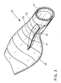
- FIG. 3 a perspective view of an inner region of a rotor blade 60 is shown in a perspective view.
- the rotor blade 60 has a circular rotor blade connection 61.
- the attachment body 51 which faces away from the leading edge, adjoins the attachment body 51 in the manner of a spoiler on the pressure side of the rotor blade 60.
- the attachment body 51 has a Aufsatzanström nature 52, wherein at the transition from the normal flow surface of the rotor blade 60 to Aufsatzanström preparation 52, the corresponding Aufus the profiles are.
- the drawn line 53 thus forms a kind of connecting line of Auf.
- the attachment inflow surface 52 of the attachment device 51 is bounded by the connection line 54 of the attachment inflow surface 52.
- the connecting line 54 are the end points of the Aufsatzanström
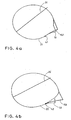
- FIGS. 4a to 4d are advantageous embodiments of an attachment device 51 or modified profiles Fig. 1 shown.
- the drawn profiles 21, 22, 23, 25 correspond to the in Fig. 1 shown profile sections.
- the modified profile sections 21, 22, 23, 25 have in this embodiment, a very high aerodynamic quality, so that the energy yield of a rotor blade in the inner rotor hub near range is maximized or is. This results in an optimized attachment device 151 (in comparison to the other attachment device 51 (cf. Fig. 1 or Fig. 2 ).
- FIGS. 4a to 4d the position of the Aufhow of the individual profile sections 21, 22, 24, 25 and the local direction of flow 31, 32, 33 and 35 clearly visible in this illustration.
- Fig. 4a to. 4c show very clearly that the profile contour in the case of the thick profiles in the region of the point of view 41, 42, 43 is substantially parallel to the direction of flow.
- the energy yield optimized design of the attachment device 151 has an even stronger displacement of the tear-off point away from the leading edge of the sheet than the geometry of FIGS Fig. 1 and 2 shown execution. However, the construction cost of such a Ausatzvorraum is high.
- Such an attachment device is particularly useful if rotor blades are to be improved during production, whereby no completely new rotor blade form has to be built.
- the illustrated attachment device can be easily mounted on an existing rotor blade.
- Fig. 5 shows the execution of an attachment device 51 with adhesive tabs 71, 72 in cross section on a profile.
- adhesive tabs 71, 72 With a rotor blade with a length of 37 m and a length of the attachment device of about 5.5 m, adhesive tabs 71, 72 with a width of 50 to 80 mm prove to be advantageous.
- the attachment 51 itself is made of 2 to 4 mm thick fiberglass (laminated fabric or fiber spray) manufactured. The tear-off is designed to achieve a high aerodynamic quality as sharp as possible corner.
- the unavoidable contour jump in the Auf Vietnamese 45 should be kept as small as possible, a maximum of 5 mm, in particular 2 to 3 mm in a glued attachment device 51 or glued spoiler.
- rounding with adhesive e.g., Sikaflex is beneficial.
Claims (15)
- Pale de rotor (60) d'une installation d'énergie éolienne comprenant un côté supérieur (côté aspiration) et un côté inférieur (côté refoulement), dans laquelle des profilés (21, 22, 23, 24, 25) sont formés dans la section avec une arête avant et une arête arrière (62) le long d'un axe longitudinal entre une racine de la pale de rotor et une pointe de la pale de rotor, une direction d'incidence de conception respective (31, 32, 33, 34, 35) est prédéfinie pour chaque profilé (21, 22, 23, 24, 25) et les profilés (21, 22, 23, 24, 25) sont réalisés, dans la zone extérieure dirigée vers la pointe de la pale de rotor, avec une épaisseur relative de moins de 30 %, caractérisée en ce qu'il est agencé le long de l'axe longitudinal, dans la zone intérieure correspondant à la racine de la pale de rotor sur les profilés (21, 22, 23, 24, 25) ayant une épaisseur relative de plus de 30 %, sur le côté refoulement, un dispositif de couronnement (51), qui présente une surface d'incidence du couronnement (52) ainsi qu'un point spatial mécanique (41, 42, 43) de la surface d'incidence du couronnement (52) dirigé vers l'arête avant et un point d'extrémité de la surface d'incidence du couronnement (52) dirigé vers l'arête arrière (62), étant entendu que le point spatial mécanique (41, 42, 43) de la surface d'incidence du couronnement (52) est agencé dans une zone comprise entre l'arête avant et l'arête arrière (62) des profilés (21, 22, 23, 24, 25) de telle sorte que la tangente avec le profilé (21, 22, 23, 24, 25) au niveau du point spatial mécanique (41, 42, 43) est formée dans une zone d'angle comprise entre +20° et -20°, en particulier entre +15° et -15°, par rapport à la direction d'incidence de conception (31, 32, 33, 34, 35) du profilé (21, 22, 23, 24, 25).
- Pale de rotor (60) selon la revendication 1, caractérisée en ce qu'il est agencé le long de l'axe longitudinal, dans la zone intérieure correspondant à la racine de la pale de rotor sur les profilés (21, 22, 23, 24, 25) ayant une épaisseur relative de plus de 30 %, sur le côté refoulement, un dispositif de couronnement (51), qui présente une surface d'incidence du couronnement (52) ainsi qu'un point spatial mécanique de la surface d'incidence du couronnement (52) dirigé vers l'arête avant et un point d'extrémité de la surface d'incidence du couronnement (52) dirigé vers l'arête arrière (62), étant entendu que le point spatial mécanique de la surface d'incidence du couronnement (52) est formé avant le point de décollement de la substance incidente sur la pale de rotor (60) sur le côté refoulement.
- Pale de rotor (60) selon la revendication 1 ou 2, caractérisée en ce que la tangente au niveau du point spatial mécanique (41, 42, 43) est réalisée sensiblement parallèlement à la direction d'incidence de conception (31, 32, 33, 34, 35).
- Pale de rotor (60) selon l'une des revendications 1 à 3, caractérisée en ce que le point d'extrémité de la surface d'incidence du couronnement (52) se termine avant l'arête arrière.
- Pale de rotor (60) selon l'une des revendications 1 à 4, caractérisée en ce que les points spatiaux mécaniques (53) de la surface d'incidence du couronnement (52) sont reliés de façon continue depuis l'intérieur vers l'extérieur.
- Pale de rotor (60) selon l'une des revendications 1 à 5, caractérisée en ce que les points d'extrémité (54) de la surface d'incidence du couronnement (52) sont reliés de façon continue depuis l'intérieur vers l'extérieur.
- Pale de rotor (60) selon l'une des revendications 1 à 6, caractérisée en ce que la distance entre les points d'extrémité (54) de la surface d'incidence du couronnement (52) et l'arête avant de la pale de rotor (60) augmente depuis l'intérieur vers l'extérieur le long de l'axe longitudinal.
- Pale de rotor (60) selon l'une des revendications 1 à 7, caractérisée en ce que le dispositif de couronnement (51) est réalisé à la manière d'un déflecteur (51).
- Pale de rotor (60) selon l'une des revendications 1 à 8, caractérisée en ce que le dispositif de couronnement (51) colle ou est collé sur la pale de rotor (60).
- Pale de rotor (60) selon l'une des revendications 1 à 9, caractérisée en ce que le dispositif de couronnement (51) peut être monté ou est monté dans un rattrapage.
- Pale de rotor (60) selon l'une des revendications 1 à 10, caractérisée en ce que le dispositif de couronnement (51) se déplace ou est déplacé depuis une position de repos vers une position de service.
- Pale de rotor (60) selon l'une des revendications 1 à 11, caractérisée en ce que le point d'extrémité de la surface d'incidence du couronnement (52) est réalisé comme point de détachement de courant.
- Installation d'énergie éolienne comprenant au moins une pale de rotor (60) selon l'une des revendications 1 à 12.
- Utilisation d'un dispositif de couronnement (51) qui est agencé ou se trouve dans une zone intérieure d'une pale de rotor (60) selon l'une des revendications 1 à 12.
- Procédé de fabrication d'une pale de rotor (60) d'une installation d'énergie éolienne, dans lequel un dispositif de couronnement (51) est agencé dans la zone intérieure de la pale de rotor (60) de telle sorte que la pale de rotor (60) est réalisée selon l'une des revendications 1 à 12.
Applications Claiming Priority (2)
| Application Number | Priority Date | Filing Date | Title |
|---|---|---|---|
| DE102006017897A DE102006017897B4 (de) | 2006-04-13 | 2006-04-13 | Rotorblatt einer Windenergieanlage |
| PCT/EP2007/002735 WO2007118581A1 (fr) | 2006-04-13 | 2007-03-28 | Pale de rotor d'un dispositif d'énergie éolienne |
Publications (2)
| Publication Number | Publication Date |
|---|---|
| EP2004990A1 EP2004990A1 (fr) | 2008-12-24 |
| EP2004990B1 true EP2004990B1 (fr) | 2013-05-15 |
Family
ID=38180302
Family Applications (1)
| Application Number | Title | Priority Date | Filing Date |
|---|---|---|---|
| EP07723681.8A Revoked EP2004990B1 (fr) | 2006-04-13 | 2007-03-28 | Pale de rotor d'un dispositif d'énergie éolienne |
Country Status (8)
| Country | Link |
|---|---|
| US (1) | US8052394B2 (fr) |
| EP (1) | EP2004990B1 (fr) |
| CN (1) | CN101711308B (fr) |
| CA (1) | CA2642840C (fr) |
| DE (1) | DE102006017897B4 (fr) |
| DK (1) | DK2004990T3 (fr) |
| ES (1) | ES2414459T3 (fr) |
| WO (1) | WO2007118581A1 (fr) |
Families Citing this family (62)
| Publication number | Priority date | Publication date | Assignee | Title |
|---|---|---|---|---|
| US7517198B2 (en) | 2006-03-20 | 2009-04-14 | Modular Wind Energy, Inc. | Lightweight composite truss wind turbine blade |
| DE102007006643A1 (de) * | 2007-02-06 | 2008-08-07 | Daubner & Stommel GbR Bau-Werk-Planung (vertretungsberechtigter Gesellschafter: Matthias Stommel, 27777 Ganderkesee) | Nachrüstteil für ein Rotorblatt einer Windenergieanlage |
| EP2031242A1 (fr) * | 2007-08-29 | 2009-03-04 | Lm Glasfiber A/S | Élément de pale pour le montage sur une pale d'éolienne et procédé pour modifier le profil aérodynamique d'une pale d'éolienne |
| ES2320962B1 (es) * | 2007-11-28 | 2010-03-11 | GAMESA INNOVATION & TECHNOLOGY S.L. | Perfil aerodinamico para la raiz de una pala de aerogenerador con doble borde de ataque. |
| DE102008026474A1 (de) * | 2008-06-03 | 2009-12-10 | Mickeler, Siegfried, Prof. Dr.-Ing. | Rotorblatt für eine Windkraftanlage sowie Windkraftanlage |
| GB2462307A (en) | 2008-08-01 | 2010-02-03 | Vestas Wind Sys As | Extension portion for wind turbine blade |
| GB2462308A (en) * | 2008-08-01 | 2010-02-03 | Vestas Wind Sys As | Extension portion for wind turbine blade |
| PL2157315T3 (pl) * | 2008-08-21 | 2018-01-31 | Lm Wind Power As | Sekcja łopaty turbiny wiatrowej |
| DE102008052858B9 (de) * | 2008-10-23 | 2014-06-12 | Senvion Se | Profil eines Rotorblatts und Rotorblatt einer Windenergieanlage |
| US7837442B2 (en) | 2008-12-03 | 2010-11-23 | General Electric Company | Root sleeve for wind turbine blade |
| EP2141358A1 (fr) * | 2008-12-12 | 2010-01-06 | Lm Glasfiber A/S | Pale d'éolienne dotée d'un déflecteur avec une séparation efficace de la circulation de l'air |
| EP2138714A1 (fr) * | 2008-12-12 | 2009-12-30 | Lm Glasfiber A/S | Pale d'éolienne dotée d'un dispositif de guidage d'écoulement de hauteur optimisée |
| DK2404055T3 (en) * | 2009-03-06 | 2016-12-12 | Vestas Wind Sys As | The wind turbine which provides increased power |
| US7988421B2 (en) | 2009-03-31 | 2011-08-02 | General Electric Company | Retrofit sleeve for wind turbine blade |
| EP2253835A1 (fr) * | 2009-05-18 | 2010-11-24 | Lm Glasfiber A/S | Pale d'éolienne avec une partie de base avec une cambrure non positive |
| EP2253839A1 (fr) * | 2009-05-18 | 2010-11-24 | Lm Glasfiber A/S | Pale d'éolienne fournie avec des dispositifs d'altération de flux |
| EP2253838A1 (fr) * | 2009-05-18 | 2010-11-24 | Lm Glasfiber A/S | Procédé de fonctionnement d'une éolienne |
| EP2253837A1 (fr) * | 2009-05-18 | 2010-11-24 | Lm Glasfiber A/S | Pale d'éolienne fournie avec des dispositifs d'altération de flux |
| EP2253836A1 (fr) * | 2009-05-18 | 2010-11-24 | Lm Glasfiber A/S | Pale d'éolienne |
| EP2253834A1 (fr) * | 2009-05-18 | 2010-11-24 | Lm Glasfiber A/S | Pale d'éolienne fournie avec des dispositifs d'altération de flux |
| DK2360374T3 (da) | 2009-10-08 | 2019-08-12 | Lm Wind Power As | Vindmøllevinge med en fremad orienteret strømningsstyringsanordning |
| DK2343451T3 (en) * | 2009-10-08 | 2018-07-23 | Lm Wind Power Int Tech Ii Aps | Wind turbine blade with a plurality of longitudinal flow controlling device parts |
| DK2343450T3 (en) | 2009-10-08 | 2019-04-15 | Lm Wind Power As | Wind turbine blade with longitudinal flow guiding device having a plate-shaped element. |
| EP2338668A1 (fr) | 2009-12-22 | 2011-06-29 | Lm Glasfiber A/S | Procédé de production d'une structure de coque composite |
| GB2476509A (en) * | 2009-12-24 | 2011-06-29 | Rolls Royce Plc | Turbine with reduced thrust coefficient at excessive speed |
| DK2366892T3 (da) * | 2010-03-18 | 2014-11-10 | Nordex Energy Gmbh | Vindenergianlægs-rotorblad |
| ES2513396T3 (es) * | 2010-03-18 | 2014-10-27 | Nordex Energy Gmbh | Pala de rotor de planta de energía eólica |
| EP2405129B1 (fr) * | 2010-07-06 | 2016-11-30 | LM WP Patent Holding A/S | Pale d'éolienne dotée d'un bord de fuite variable |
| JP5479300B2 (ja) * | 2010-10-22 | 2014-04-23 | 三菱重工業株式会社 | 風車翼およびこれを備えた風力発電装置ならびに風車翼の設計方法 |
| US8523515B2 (en) | 2010-11-15 | 2013-09-03 | General Electric Company | Noise reducer for rotor blade in wind turbine |
| DK2479423T3 (en) * | 2011-01-24 | 2018-05-28 | Siemens Ag | Wind turbine rotor blade element |
| DE102011012965B4 (de) * | 2011-03-04 | 2015-10-22 | Deutsche Windtechnik AG | Rotorblatt für Windenergieanlagen mit horizontaler Drehachse sowie Windenergieanlage mit selbigem |
| US8047784B2 (en) * | 2011-03-22 | 2011-11-01 | General Electric Company | Lift device for rotor blade in wind turbine |
| EP2514962B1 (fr) * | 2011-04-19 | 2017-08-02 | Siemens Aktiengesellschaft | Déflecteur pour pale d'éolienne |
| EP2514961B1 (fr) * | 2011-04-19 | 2017-09-13 | Siemens Aktiengesellschaft | Déflecteur pour pale de rotor d'éolienne |
| US8414261B2 (en) | 2011-05-31 | 2013-04-09 | General Electric Company | Noise reducer for rotor blade in wind turbine |
| GB201109412D0 (en) * | 2011-06-03 | 2011-07-20 | Blade Dynamics Ltd | A wind turbine rotor |
| US8834127B2 (en) | 2011-09-09 | 2014-09-16 | General Electric Company | Extension for rotor blade in wind turbine |
| US8430638B2 (en) | 2011-12-19 | 2013-04-30 | General Electric Company | Noise reducer for rotor blade in wind turbine |
| DK2815125T3 (en) * | 2012-02-17 | 2018-07-30 | Lm Wind Power Int Tech Ii Aps | WIND TURBINE BLADE HAVING A SHAPED STALL FENCE OR FLOW DIVERTER |
| WO2013137716A2 (fr) | 2012-03-13 | 2013-09-19 | Corten Holding Bv | Base de pale vrillée |
| EP2713044B2 (fr) * | 2012-09-28 | 2022-12-07 | Siemens Gamesa Renewable Energy A/S | Pale de rotor d'éolienne |
| US9377005B2 (en) | 2013-03-15 | 2016-06-28 | General Electric Company | Airfoil modifiers for wind turbine rotor blades |
| US20150050154A1 (en) * | 2013-05-23 | 2015-02-19 | Kristian R. DIXON | Airfoil trailing edge apparatus for noise reduction |
| DE102013210901A1 (de) * | 2013-06-11 | 2014-12-11 | Wobben Properties Gmbh | Rotorblatt einer Windenergieanlage und Windenergieanlage |
| DE102014203442A1 (de) * | 2013-11-04 | 2015-05-07 | Senvion Se | Rotorblatt einer Windenergieanlage und Windenergieanlage |
| US9494134B2 (en) | 2013-11-20 | 2016-11-15 | General Electric Company | Noise reducing extension plate for rotor blade in wind turbine |
| EP3169896B1 (fr) * | 2014-07-14 | 2019-11-27 | LM WP Patent Holding A/S | Coque d'extension pour pale d'éolienne |
| CA2956415C (fr) | 2014-08-05 | 2023-02-07 | Lm Wp Patent Holding A/S | Pale d'eolienne dotee d'un dispositif monte en surface |
| GB201419389D0 (en) | 2014-10-31 | 2014-12-17 | Lm Wp Patent Holding As | Wind turbine blade provided with surface mounted device |
| DE102014215966A1 (de) | 2014-08-12 | 2016-02-18 | Senvion Gmbh | Rotorblattverlängerungskörper sowie Windenergieanlage |
| CN104595110A (zh) * | 2014-12-01 | 2015-05-06 | 东方电气集团东方汽轮机有限公司 | 一种风机风轮调整装置及包含该装置的风机组 |
| US10180125B2 (en) | 2015-04-20 | 2019-01-15 | General Electric Company | Airflow configuration for a wind turbine rotor blade |
| EP3329117B1 (fr) * | 2015-09-03 | 2021-02-17 | Siemens Gamesa Renewable Energy A/S | Pale d'éolienne pourvue d'un volet de bord de fuite |
| CN106545465A (zh) * | 2017-01-25 | 2017-03-29 | 北京博比风电科技有限公司 | 延迟分离尾缘叶片 |
| US10465652B2 (en) | 2017-01-26 | 2019-11-05 | General Electric Company | Vortex generators for wind turbine rotor blades having noise-reducing features |
| US20190024631A1 (en) * | 2017-07-20 | 2019-01-24 | General Electric Company | Airflow configuration for a wind turbine rotor blade |
| US11040767B2 (en) * | 2017-11-30 | 2021-06-22 | General Electric Company | Systems and methods for improved propeller design |
| US10767623B2 (en) | 2018-04-13 | 2020-09-08 | General Electric Company | Serrated noise reducer for a wind turbine rotor blade |
| US10746157B2 (en) | 2018-08-31 | 2020-08-18 | General Electric Company | Noise reducer for a wind turbine rotor blade having a cambered serration |
| EP3851667A1 (fr) | 2020-01-16 | 2021-07-21 | Nordex Energy Spain, S.A.U. | Pale de turbine éolienne |
| EP4008894A1 (fr) * | 2020-12-02 | 2022-06-08 | Siemens Gamesa Renewable Energy A/S | Pale de rotor pour éolienne |
Family Cites Families (14)
| Publication number | Priority date | Publication date | Assignee | Title |
|---|---|---|---|---|
| CN85105039B (zh) * | 1985-06-29 | 1988-07-06 | 库斯托基金会 | 流体动力装置 |
| DK9500009U3 (da) * | 1995-01-10 | 1996-04-10 | Stiesdal Bonus Energy A Henrik | Organ til forbedring af en vindmølles virkningsgrad |
| DE19815519A1 (de) * | 1998-03-31 | 1999-10-07 | Tacke Windenergie Gmbh | Rotorblatt für eine Windkraftanlage |
| NL1012949C2 (nl) * | 1999-09-01 | 2001-03-06 | Stichting Energie | Blad voor een windturbine. |
| DE50115739D1 (de) * | 1999-12-31 | 2011-01-27 | Deutsch Zentr Luft & Raumfahrt | Flügelprofil mit leistungs-steigernder Hinterkante |
| NL1015558C2 (nl) * | 2000-06-28 | 2002-01-08 | Stichting En Onderzoek Ct Nede | Blad van een windturbine. |
| WO2002038442A2 (fr) * | 2000-10-10 | 2002-05-16 | The Regents Of The University Of California | Volets translationnels microfabriques permettant de reguler la charge aerodynamique |
| DE10319246A1 (de) | 2003-04-28 | 2004-12-16 | Aloys Wobben | Rotorblatt einer Windenergieanlage |
| DK200300670A (da) * | 2003-05-05 | 2004-11-06 | Lm Glasfiber As | Vindmölleving med opdriftsregulerende organer |
| DE10347802B3 (de) * | 2003-10-10 | 2005-05-19 | Repower Systems Ag | Rotorblatt für eine Windkraftanlage |
| DE102004007487A1 (de) * | 2004-02-13 | 2005-09-01 | Aloys Wobben | Rotorblatt einer Windenergieanlage |
| US7637721B2 (en) * | 2005-07-29 | 2009-12-29 | General Electric Company | Methods and apparatus for producing wind energy with reduced wind turbine noise |
| EP1845258A1 (fr) | 2006-04-10 | 2007-10-17 | Siemens Aktiengesellschaft | Pale de rotor d'éolienne |
| US7918653B2 (en) * | 2007-02-07 | 2011-04-05 | General Electric Company | Rotor blade trailing edge assemby and method of use |
-
2006
- 2006-04-13 DE DE102006017897A patent/DE102006017897B4/de not_active Revoked
-
2007
- 2007-03-28 CN CN2007800133567A patent/CN101711308B/zh not_active Expired - Fee Related
- 2007-03-28 US US12/296,745 patent/US8052394B2/en not_active Expired - Fee Related
- 2007-03-28 DK DK07723681.8T patent/DK2004990T3/da active
- 2007-03-28 CA CA2642840A patent/CA2642840C/fr active Active
- 2007-03-28 ES ES07723681T patent/ES2414459T3/es active Active
- 2007-03-28 EP EP07723681.8A patent/EP2004990B1/fr not_active Revoked
- 2007-03-28 WO PCT/EP2007/002735 patent/WO2007118581A1/fr active Application Filing
Also Published As
| Publication number | Publication date |
|---|---|
| DE102006017897A1 (de) | 2007-10-18 |
| US20090274559A1 (en) | 2009-11-05 |
| EP2004990A1 (fr) | 2008-12-24 |
| CA2642840C (fr) | 2013-03-05 |
| WO2007118581A1 (fr) | 2007-10-25 |
| CN101711308B (zh) | 2013-03-13 |
| DE102006017897B4 (de) | 2008-03-13 |
| CN101711308A (zh) | 2010-05-19 |
| CA2642840A1 (fr) | 2007-10-25 |
| ES2414459T3 (es) | 2013-07-19 |
| DK2004990T3 (da) | 2013-08-19 |
| US8052394B2 (en) | 2011-11-08 |
Similar Documents
| Publication | Publication Date | Title |
|---|---|---|
| EP2004990B1 (fr) | Pale de rotor d'un dispositif d'énergie éolienne | |
| EP1514023B1 (fr) | Eolienne | |
| EP2366891B1 (fr) | Pale de rotor d'éolienne | |
| EP3008331B1 (fr) | Pale de rotor d'une éolienne et éolienne | |
| EP2258943A2 (fr) | Profil d'une pale de rotor d'une éolienne | |
| EP2280163B1 (fr) | Eolienne et pale de rotor d'une eolienne | |
| WO2005085633A1 (fr) | Eolienne a axe de rotation vertical et corps de deviation central | |
| DE19963086C1 (de) | Rotorblatt für eine Windenergieanlage | |
| EP3066337B1 (fr) | Pale de rotor d'une éolienne et éolienne | |
| EP2594784A2 (fr) | Éolienne verticale et pale de rotor pour celle-ci | |
| EP2366892B1 (fr) | Pale de rotor d'éolienne | |
| DE202016101461U1 (de) | Rotorblatt für Windenergieanlagen mit horizontaler Drehachse sowieWindenergieanlage mit selbigem | |
| DE102013206437A1 (de) | Rotorblatt einer Windenergieanlage und Windenergieanlage | |
| EP2568166B1 (fr) | Pale de rotor d'éolienne dotée d'un rebord arrière à profil épais | |
| EP3399183B1 (fr) | Pale de rotor d'une éolienne | |
| WO2009095149A2 (fr) | Installation de production d'énergie immergée indépendante munie d'une turbine axiale | |
| EP2281743B1 (fr) | Pod | |
| EP2976524B1 (fr) | Pale de rotor d'une éolienne, éolienne, et procédé pour faire fonctionner une éolienne | |
| EP2978967B1 (fr) | Pale de rotor munie d'une penne pour éolienne | |
| WO2011069615A1 (fr) | Aube de turbine pour une turbine à eau pouvant être alimentée de manière bidirectionnelle | |
| EP3981981A1 (fr) | Pale de rotor pour une éolienne, éolienne et procédé de conception d'une pale de rotor | |
| WO2016162350A1 (fr) | Pale de rotor d'éolienne | |
| DE102011011084A1 (de) | Rotorblatt für eine Windenergieanlage mit einer ausfahrbaren Blattvergrößerung | |
| DE102007059285A1 (de) | Rotorblatt für Windenergieanlagen | |
| DE102022121502A1 (de) | Rotorblatt für eine Windenergieanlage sowie Rotorblattspitze |
Legal Events
| Date | Code | Title | Description |
|---|---|---|---|
| PUAI | Public reference made under article 153(3) epc to a published international application that has entered the european phase |
Free format text: ORIGINAL CODE: 0009012 |
|
| 17P | Request for examination filed |
Effective date: 20080809 |
|
| AK | Designated contracting states |
Kind code of ref document: A1 Designated state(s): AT BE BG CH CY CZ DE DK EE ES FI FR GB GR HU IE IS IT LI LT LU LV MC MT NL PL PT RO SE SI SK TR |
|
| 17Q | First examination report despatched |
Effective date: 20091208 |
|
| DAX | Request for extension of the european patent (deleted) | ||
| GRAP | Despatch of communication of intention to grant a patent |
Free format text: ORIGINAL CODE: EPIDOSNIGR1 |
|
| GRAS | Grant fee paid |
Free format text: ORIGINAL CODE: EPIDOSNIGR3 |
|
| GRAA | (expected) grant |
Free format text: ORIGINAL CODE: 0009210 |
|
| RAP1 | Party data changed (applicant data changed or rights of an application transferred) |
Owner name: REPOWER SYSTEMS SE |
|
| AK | Designated contracting states |
Kind code of ref document: B1 Designated state(s): AT BE BG CH CY CZ DE DK EE ES FI FR GB GR HU IE IS IT LI LT LU LV MC MT NL PL PT RO SE SI SK TR |
|
| REG | Reference to a national code |
Ref country code: GB Ref legal event code: FG4D Free format text: NOT ENGLISH Ref country code: CH Ref legal event code: EP |
|
| REG | Reference to a national code |
Ref country code: AT Ref legal event code: REF Ref document number: 612292 Country of ref document: AT Kind code of ref document: T Effective date: 20130615 |
|
| REG | Reference to a national code |
Ref country code: IE Ref legal event code: FG4D Free format text: LANGUAGE OF EP DOCUMENT: GERMAN |
|
| REG | Reference to a national code |
Ref country code: DE Ref legal event code: R096 Ref document number: 502007011763 Country of ref document: DE Effective date: 20130711 |
|
| REG | Reference to a national code |
Ref country code: ES Ref legal event code: FG2A Ref document number: 2414459 Country of ref document: ES Kind code of ref document: T3 Effective date: 20130719 |
|
| REG | Reference to a national code |
Ref country code: DK Ref legal event code: T3 |
|
| REG | Reference to a national code |
Ref country code: LT Ref legal event code: MG4D |
|
| REG | Reference to a national code |
Ref country code: NL Ref legal event code: VDEP Effective date: 20130515 |
|
| PG25 | Lapsed in a contracting state [announced via postgrant information from national office to epo] |
Ref country code: SI Free format text: LAPSE BECAUSE OF FAILURE TO SUBMIT A TRANSLATION OF THE DESCRIPTION OR TO PAY THE FEE WITHIN THE PRESCRIBED TIME-LIMIT Effective date: 20130515 Ref country code: LT Free format text: LAPSE BECAUSE OF FAILURE TO SUBMIT A TRANSLATION OF THE DESCRIPTION OR TO PAY THE FEE WITHIN THE PRESCRIBED TIME-LIMIT Effective date: 20130515 Ref country code: PT Free format text: LAPSE BECAUSE OF FAILURE TO SUBMIT A TRANSLATION OF THE DESCRIPTION OR TO PAY THE FEE WITHIN THE PRESCRIBED TIME-LIMIT Effective date: 20130916 Ref country code: GR Free format text: LAPSE BECAUSE OF FAILURE TO SUBMIT A TRANSLATION OF THE DESCRIPTION OR TO PAY THE FEE WITHIN THE PRESCRIBED TIME-LIMIT Effective date: 20130816 Ref country code: SE Free format text: LAPSE BECAUSE OF FAILURE TO SUBMIT A TRANSLATION OF THE DESCRIPTION OR TO PAY THE FEE WITHIN THE PRESCRIBED TIME-LIMIT Effective date: 20130515 Ref country code: FI Free format text: LAPSE BECAUSE OF FAILURE TO SUBMIT A TRANSLATION OF THE DESCRIPTION OR TO PAY THE FEE WITHIN THE PRESCRIBED TIME-LIMIT Effective date: 20130515 Ref country code: IS Free format text: LAPSE BECAUSE OF FAILURE TO SUBMIT A TRANSLATION OF THE DESCRIPTION OR TO PAY THE FEE WITHIN THE PRESCRIBED TIME-LIMIT Effective date: 20130915 |
|
| PG25 | Lapsed in a contracting state [announced via postgrant information from national office to epo] |
Ref country code: PL Free format text: LAPSE BECAUSE OF FAILURE TO SUBMIT A TRANSLATION OF THE DESCRIPTION OR TO PAY THE FEE WITHIN THE PRESCRIBED TIME-LIMIT Effective date: 20130515 Ref country code: BG Free format text: LAPSE BECAUSE OF FAILURE TO SUBMIT A TRANSLATION OF THE DESCRIPTION OR TO PAY THE FEE WITHIN THE PRESCRIBED TIME-LIMIT Effective date: 20130815 |
|
| PG25 | Lapsed in a contracting state [announced via postgrant information from national office to epo] |
Ref country code: LV Free format text: LAPSE BECAUSE OF FAILURE TO SUBMIT A TRANSLATION OF THE DESCRIPTION OR TO PAY THE FEE WITHIN THE PRESCRIBED TIME-LIMIT Effective date: 20130515 |
|
| PG25 | Lapsed in a contracting state [announced via postgrant information from national office to epo] |
Ref country code: CZ Free format text: LAPSE BECAUSE OF FAILURE TO SUBMIT A TRANSLATION OF THE DESCRIPTION OR TO PAY THE FEE WITHIN THE PRESCRIBED TIME-LIMIT Effective date: 20130515 Ref country code: SK Free format text: LAPSE BECAUSE OF FAILURE TO SUBMIT A TRANSLATION OF THE DESCRIPTION OR TO PAY THE FEE WITHIN THE PRESCRIBED TIME-LIMIT Effective date: 20130515 Ref country code: EE Free format text: LAPSE BECAUSE OF FAILURE TO SUBMIT A TRANSLATION OF THE DESCRIPTION OR TO PAY THE FEE WITHIN THE PRESCRIBED TIME-LIMIT Effective date: 20130515 |
|
| PG25 | Lapsed in a contracting state [announced via postgrant information from national office to epo] |
Ref country code: IT Free format text: LAPSE BECAUSE OF FAILURE TO SUBMIT A TRANSLATION OF THE DESCRIPTION OR TO PAY THE FEE WITHIN THE PRESCRIBED TIME-LIMIT Effective date: 20130515 Ref country code: RO Free format text: LAPSE BECAUSE OF FAILURE TO SUBMIT A TRANSLATION OF THE DESCRIPTION OR TO PAY THE FEE WITHIN THE PRESCRIBED TIME-LIMIT Effective date: 20130515 Ref country code: NL Free format text: LAPSE BECAUSE OF FAILURE TO SUBMIT A TRANSLATION OF THE DESCRIPTION OR TO PAY THE FEE WITHIN THE PRESCRIBED TIME-LIMIT Effective date: 20130515 |
|
| PLBI | Opposition filed |
Free format text: ORIGINAL CODE: 0009260 |
|
| PLAX | Notice of opposition and request to file observation + time limit sent |
Free format text: ORIGINAL CODE: EPIDOSNOBS2 |
|
| 26 | Opposition filed |
Opponent name: SIEMENS AKTIENGESELLSCHAFT Effective date: 20140217 Opponent name: LM WP PATENT HOLDING A/S Effective date: 20140214 Opponent name: VESTAS WIND SYSTEMS A/S Effective date: 20140214 |
|
| REG | Reference to a national code |
Ref country code: DE Ref legal event code: R026 Ref document number: 502007011763 Country of ref document: DE Effective date: 20140214 |
|
| PLAF | Information modified related to communication of a notice of opposition and request to file observations + time limit |
Free format text: ORIGINAL CODE: EPIDOSCOBS2 |
|
| RAP2 | Party data changed (patent owner data changed or rights of a patent transferred) |
Owner name: SENVION SE |
|
| PLBB | Reply of patent proprietor to notice(s) of opposition received |
Free format text: ORIGINAL CODE: EPIDOSNOBS3 |
|
| PG25 | Lapsed in a contracting state [announced via postgrant information from national office to epo] |
Ref country code: LU Free format text: LAPSE BECAUSE OF FAILURE TO SUBMIT A TRANSLATION OF THE DESCRIPTION OR TO PAY THE FEE WITHIN THE PRESCRIBED TIME-LIMIT Effective date: 20140328 |
|
| REG | Reference to a national code |
Ref country code: CH Ref legal event code: PL |
|
| GBPC | Gb: european patent ceased through non-payment of renewal fee |
Effective date: 20140328 |
|
| RAP2 | Party data changed (patent owner data changed or rights of a patent transferred) |
Owner name: SENVION SE |
|
| REG | Reference to a national code |
Ref country code: FR Ref legal event code: ST Effective date: 20141128 |
|
| REG | Reference to a national code |
Ref country code: IE Ref legal event code: MM4A |
|
| PG25 | Lapsed in a contracting state [announced via postgrant information from national office to epo] |
Ref country code: LI Free format text: LAPSE BECAUSE OF NON-PAYMENT OF DUE FEES Effective date: 20140331 Ref country code: IE Free format text: LAPSE BECAUSE OF NON-PAYMENT OF DUE FEES Effective date: 20140328 Ref country code: GB Free format text: LAPSE BECAUSE OF NON-PAYMENT OF DUE FEES Effective date: 20140328 Ref country code: FR Free format text: LAPSE BECAUSE OF NON-PAYMENT OF DUE FEES Effective date: 20140331 Ref country code: CH Free format text: LAPSE BECAUSE OF NON-PAYMENT OF DUE FEES Effective date: 20140331 |
|
| REG | Reference to a national code |
Ref country code: DE Ref legal event code: R082 Ref document number: 502007011763 Country of ref document: DE Representative=s name: PATENTANWAELTE SEEMANN & PARTNER, DE |
|
| REG | Reference to a national code |
Ref country code: DE Ref legal event code: R082 Ref document number: 502007011763 Country of ref document: DE Representative=s name: PATENTANWAELTE SEEMANN & PARTNER, DE Effective date: 20150227 Ref country code: DE Ref legal event code: R081 Ref document number: 502007011763 Country of ref document: DE Owner name: SENVION SE, DE Free format text: FORMER OWNER: REPOWER SYSTEMS SE, 22297 HAMBURG, DE Effective date: 20150227 Ref country code: DE Ref legal event code: R081 Ref document number: 502007011763 Country of ref document: DE Owner name: SENVION GMBH, DE Free format text: FORMER OWNER: REPOWER SYSTEMS SE, 22297 HAMBURG, DE Effective date: 20150227 Ref country code: DE Ref legal event code: R082 Ref document number: 502007011763 Country of ref document: DE Representative=s name: WALLINGER RICKER SCHLOTTER TOSTMANN PATENT- UN, DE Effective date: 20150227 Ref country code: DE Ref legal event code: R082 Ref document number: 502007011763 Country of ref document: DE Representative=s name: SEEMANN & PARTNER PATENTANWAELTE MBB, DE Effective date: 20150227 |
|
| REG | Reference to a national code |
Ref country code: AT Ref legal event code: MM01 Ref document number: 612292 Country of ref document: AT Kind code of ref document: T Effective date: 20140328 |
|
| REG | Reference to a national code |
Ref country code: DE Ref legal event code: R082 Ref document number: 502007011763 Country of ref document: DE Representative=s name: PATENTANWAELTE SEEMANN & PARTNER, DE Ref country code: DE Ref legal event code: R081 Ref document number: 502007011763 Country of ref document: DE Owner name: SENVION GMBH, DE Free format text: FORMER OWNER: SENVION SE, 22297 HAMBURG, DE Ref country code: DE Ref legal event code: R082 Ref document number: 502007011763 Country of ref document: DE Representative=s name: WALLINGER RICKER SCHLOTTER TOSTMANN PATENT- UN, DE Ref country code: DE Ref legal event code: R082 Ref document number: 502007011763 Country of ref document: DE Representative=s name: SEEMANN & PARTNER PATENTANWAELTE MBB, DE |
|
| PG25 | Lapsed in a contracting state [announced via postgrant information from national office to epo] |
Ref country code: AT Free format text: LAPSE BECAUSE OF NON-PAYMENT OF DUE FEES Effective date: 20140328 |
|
| RAP2 | Party data changed (patent owner data changed or rights of a patent transferred) |
Owner name: SENVION GMBH |
|
| PG25 | Lapsed in a contracting state [announced via postgrant information from national office to epo] |
Ref country code: MT Free format text: LAPSE BECAUSE OF FAILURE TO SUBMIT A TRANSLATION OF THE DESCRIPTION OR TO PAY THE FEE WITHIN THE PRESCRIBED TIME-LIMIT Effective date: 20130515 |
|
| PG25 | Lapsed in a contracting state [announced via postgrant information from national office to epo] |
Ref country code: MC Free format text: LAPSE BECAUSE OF FAILURE TO SUBMIT A TRANSLATION OF THE DESCRIPTION OR TO PAY THE FEE WITHIN THE PRESCRIBED TIME-LIMIT Effective date: 20130515 |
|
| PG25 | Lapsed in a contracting state [announced via postgrant information from national office to epo] |
Ref country code: CY Free format text: LAPSE BECAUSE OF FAILURE TO SUBMIT A TRANSLATION OF THE DESCRIPTION OR TO PAY THE FEE WITHIN THE PRESCRIBED TIME-LIMIT Effective date: 20130515 |
|
| PG25 | Lapsed in a contracting state [announced via postgrant information from national office to epo] |
Ref country code: HU Free format text: LAPSE BECAUSE OF FAILURE TO SUBMIT A TRANSLATION OF THE DESCRIPTION OR TO PAY THE FEE WITHIN THE PRESCRIBED TIME-LIMIT; INVALID AB INITIO Effective date: 20070328 Ref country code: TR Free format text: LAPSE BECAUSE OF FAILURE TO SUBMIT A TRANSLATION OF THE DESCRIPTION OR TO PAY THE FEE WITHIN THE PRESCRIBED TIME-LIMIT Effective date: 20130515 |
|
| PLCK | Communication despatched that opposition was rejected |
Free format text: ORIGINAL CODE: EPIDOSNREJ1 |
|
| APAW | Appeal reference deleted |
Free format text: ORIGINAL CODE: EPIDOSDREFNO |
|
| APAY | Date of receipt of notice of appeal deleted |
Free format text: ORIGINAL CODE: EPIDOSDNOA2O |
|
| APBM | Appeal reference recorded |
Free format text: ORIGINAL CODE: EPIDOSNREFNO |
|
| APBP | Date of receipt of notice of appeal recorded |
Free format text: ORIGINAL CODE: EPIDOSNNOA2O |
|
| APAH | Appeal reference modified |
Free format text: ORIGINAL CODE: EPIDOSCREFNO |
|
| APAW | Appeal reference deleted |
Free format text: ORIGINAL CODE: EPIDOSDREFNO |
|
| APAY | Date of receipt of notice of appeal deleted |
Free format text: ORIGINAL CODE: EPIDOSDNOA2O |
|
| APBM | Appeal reference recorded |
Free format text: ORIGINAL CODE: EPIDOSNREFNO |
|
| APBP | Date of receipt of notice of appeal recorded |
Free format text: ORIGINAL CODE: EPIDOSNNOA2O |
|
| APBM | Appeal reference recorded |
Free format text: ORIGINAL CODE: EPIDOSNREFNO |
|
| APBP | Date of receipt of notice of appeal recorded |
Free format text: ORIGINAL CODE: EPIDOSNNOA2O |
|
| APBQ | Date of receipt of statement of grounds of appeal recorded |
Free format text: ORIGINAL CODE: EPIDOSNNOA3O |
|
| APBQ | Date of receipt of statement of grounds of appeal recorded |
Free format text: ORIGINAL CODE: EPIDOSNNOA3O |
|
| PG25 | Lapsed in a contracting state [announced via postgrant information from national office to epo] |
Ref country code: BE Free format text: LAPSE BECAUSE OF NON-PAYMENT OF DUE FEES Effective date: 20140331 |
|
| PLAB | Opposition data, opponent's data or that of the opponent's representative modified |
Free format text: ORIGINAL CODE: 0009299OPPO |
|
| R26 | Opposition filed (corrected) |
Opponent name: SIEMENS AKTIENGESELLSCHAFT Effective date: 20140217 |
|
| PLAB | Opposition data, opponent's data or that of the opponent's representative modified |
Free format text: ORIGINAL CODE: 0009299OPPO |
|
| R26 | Opposition filed (corrected) |
Opponent name: LM WP PATENT HOLDING A/S Effective date: 20140214 |
|
| REG | Reference to a national code |
Ref country code: DE Ref legal event code: R082 Ref document number: 502007011763 Country of ref document: DE Representative=s name: WALLINGER RICKER SCHLOTTER TOSTMANN PATENT- UN, DE |
|
| PLAB | Opposition data, opponent's data or that of the opponent's representative modified |
Free format text: ORIGINAL CODE: 0009299OPPO |
|
| R26 | Opposition filed (corrected) |
Opponent name: LM WP PATENT HOLDING A/S Effective date: 20140214 |
|
| PLBP | Opposition withdrawn |
Free format text: ORIGINAL CODE: 0009264 |
|
| PGFP | Annual fee paid to national office [announced via postgrant information from national office to epo] |
Ref country code: DK Payment date: 20200323 Year of fee payment: 14 Ref country code: DE Payment date: 20200324 Year of fee payment: 14 |
|
| PGFP | Annual fee paid to national office [announced via postgrant information from national office to epo] |
Ref country code: ES Payment date: 20200421 Year of fee payment: 14 |
|
| RAP2 | Party data changed (patent owner data changed or rights of a patent transferred) |
Owner name: SENVION DEUTSCHLAND GMBH |
|
| REG | Reference to a national code |
Ref country code: DE Ref legal event code: R064 Ref document number: 502007011763 Country of ref document: DE Ref country code: DE Ref legal event code: R103 Ref document number: 502007011763 Country of ref document: DE |
|
| APBU | Appeal procedure closed |
Free format text: ORIGINAL CODE: EPIDOSNNOA9O |
|
| RDAF | Communication despatched that patent is revoked |
Free format text: ORIGINAL CODE: EPIDOSNREV1 |
|
| RDAG | Patent revoked |
Free format text: ORIGINAL CODE: 0009271 |
|
| STAA | Information on the status of an ep patent application or granted ep patent |
Free format text: STATUS: PATENT REVOKED |
|
| 27W | Patent revoked |
Effective date: 20201102 |
|
| REG | Reference to a national code |
Ref country code: FI Ref legal event code: MGE |
|
| REG | Reference to a national code |
Ref country code: AT Ref legal event code: MA03 Ref document number: 612292 Country of ref document: AT Kind code of ref document: T Effective date: 20201102 |