EP2004990B1 - Rotorblatt einer windenergieanlage - Google Patents
Rotorblatt einer windenergieanlage Download PDFInfo
- Publication number
- EP2004990B1 EP2004990B1 EP07723681.8A EP07723681A EP2004990B1 EP 2004990 B1 EP2004990 B1 EP 2004990B1 EP 07723681 A EP07723681 A EP 07723681A EP 2004990 B1 EP2004990 B1 EP 2004990B1
- Authority
- EP
- European Patent Office
- Prior art keywords
- rotor blade
- attached device
- profile
- attachment device
- profiles
- Prior art date
- Legal status (The legal status is an assumption and is not a legal conclusion. Google has not performed a legal analysis and makes no representation as to the accuracy of the status listed.)
- Revoked
Links
- 239000000853 adhesive Substances 0.000 claims description 6
- 230000001070 adhesive effect Effects 0.000 claims description 6
- 238000000034 method Methods 0.000 claims description 3
- 238000004519 manufacturing process Methods 0.000 description 8
- 238000010276 construction Methods 0.000 description 5
- 230000007423 decrease Effects 0.000 description 3
- 239000011152 fibreglass Substances 0.000 description 3
- 230000002441 reversible effect Effects 0.000 description 3
- 238000000926 separation method Methods 0.000 description 3
- 230000007704 transition Effects 0.000 description 3
- 238000011161 development Methods 0.000 description 2
- 230000002349 favourable effect Effects 0.000 description 2
- 206010024229 Leprosy Diseases 0.000 description 1
- 230000009286 beneficial effect Effects 0.000 description 1
- 238000004364 calculation method Methods 0.000 description 1
- 238000012938 design process Methods 0.000 description 1
- 238000006073 displacement reaction Methods 0.000 description 1
- 239000004744 fabric Substances 0.000 description 1
- 239000000835 fiber Substances 0.000 description 1
- 239000000463 material Substances 0.000 description 1
- 230000002093 peripheral effect Effects 0.000 description 1
- 230000000284 resting effect Effects 0.000 description 1
- 239000007921 spray Substances 0.000 description 1
- XLYOFNOQVPJJNP-UHFFFAOYSA-N water Substances O XLYOFNOQVPJJNP-UHFFFAOYSA-N 0.000 description 1
Images


Classifications
-
- F—MECHANICAL ENGINEERING; LIGHTING; HEATING; WEAPONS; BLASTING
- F03—MACHINES OR ENGINES FOR LIQUIDS; WIND, SPRING, OR WEIGHT MOTORS; PRODUCING MECHANICAL POWER OR A REACTIVE PROPULSIVE THRUST, NOT OTHERWISE PROVIDED FOR
- F03D—WIND MOTORS
- F03D1/00—Wind motors with rotation axis substantially parallel to the air flow entering the rotor
- F03D1/06—Rotors
- F03D1/0608—Rotors characterised by their aerodynamic shape
- F03D1/0633—Rotors characterised by their aerodynamic shape of the blades
- F03D1/0641—Rotors characterised by their aerodynamic shape of the blades of the section profile of the blades, i.e. aerofoil profile
-
- F—MECHANICAL ENGINEERING; LIGHTING; HEATING; WEAPONS; BLASTING
- F05—INDEXING SCHEMES RELATING TO ENGINES OR PUMPS IN VARIOUS SUBCLASSES OF CLASSES F01-F04
- F05B—INDEXING SCHEME RELATING TO WIND, SPRING, WEIGHT, INERTIA OR LIKE MOTORS, TO MACHINES OR ENGINES FOR LIQUIDS COVERED BY SUBCLASSES F03B, F03D AND F03G
- F05B2240/00—Components
- F05B2240/20—Rotors
- F05B2240/30—Characteristics of rotor blades, i.e. of any element transforming dynamic fluid energy to or from rotational energy and being attached to a rotor
- F05B2240/301—Cross-section characteristics
-
- F—MECHANICAL ENGINEERING; LIGHTING; HEATING; WEAPONS; BLASTING
- F05—INDEXING SCHEMES RELATING TO ENGINES OR PUMPS IN VARIOUS SUBCLASSES OF CLASSES F01-F04
- F05B—INDEXING SCHEME RELATING TO WIND, SPRING, WEIGHT, INERTIA OR LIKE MOTORS, TO MACHINES OR ENGINES FOR LIQUIDS COVERED BY SUBCLASSES F03B, F03D AND F03G
- F05B2240/00—Components
- F05B2240/20—Rotors
- F05B2240/30—Characteristics of rotor blades, i.e. of any element transforming dynamic fluid energy to or from rotational energy and being attached to a rotor
- F05B2240/31—Characteristics of rotor blades, i.e. of any element transforming dynamic fluid energy to or from rotational energy and being attached to a rotor of changeable form or shape
-
- Y—GENERAL TAGGING OF NEW TECHNOLOGICAL DEVELOPMENTS; GENERAL TAGGING OF CROSS-SECTIONAL TECHNOLOGIES SPANNING OVER SEVERAL SECTIONS OF THE IPC; TECHNICAL SUBJECTS COVERED BY FORMER USPC CROSS-REFERENCE ART COLLECTIONS [XRACs] AND DIGESTS
- Y02—TECHNOLOGIES OR APPLICATIONS FOR MITIGATION OR ADAPTATION AGAINST CLIMATE CHANGE
- Y02E—REDUCTION OF GREENHOUSE GAS [GHG] EMISSIONS, RELATED TO ENERGY GENERATION, TRANSMISSION OR DISTRIBUTION
- Y02E10/00—Energy generation through renewable energy sources
- Y02E10/70—Wind energy
- Y02E10/72—Wind turbines with rotation axis in wind direction
-
- Y—GENERAL TAGGING OF NEW TECHNOLOGICAL DEVELOPMENTS; GENERAL TAGGING OF CROSS-SECTIONAL TECHNOLOGIES SPANNING OVER SEVERAL SECTIONS OF THE IPC; TECHNICAL SUBJECTS COVERED BY FORMER USPC CROSS-REFERENCE ART COLLECTIONS [XRACs] AND DIGESTS
- Y02—TECHNOLOGIES OR APPLICATIONS FOR MITIGATION OR ADAPTATION AGAINST CLIMATE CHANGE
- Y02P—CLIMATE CHANGE MITIGATION TECHNOLOGIES IN THE PRODUCTION OR PROCESSING OF GOODS
- Y02P70/00—Climate change mitigation technologies in the production process for final industrial or consumer products
- Y02P70/50—Manufacturing or production processes characterised by the final manufactured product
-
- Y—GENERAL TAGGING OF NEW TECHNOLOGICAL DEVELOPMENTS; GENERAL TAGGING OF CROSS-SECTIONAL TECHNOLOGIES SPANNING OVER SEVERAL SECTIONS OF THE IPC; TECHNICAL SUBJECTS COVERED BY FORMER USPC CROSS-REFERENCE ART COLLECTIONS [XRACs] AND DIGESTS
- Y10—TECHNICAL SUBJECTS COVERED BY FORMER USPC
- Y10T—TECHNICAL SUBJECTS COVERED BY FORMER US CLASSIFICATION
- Y10T29/00—Metal working
- Y10T29/49—Method of mechanical manufacture
- Y10T29/49316—Impeller making
- Y10T29/49336—Blade making
- Y10T29/49337—Composite blade
Definitions
- the invention relates to a rotor blade of a wind turbine with an upper side (suction side) and a lower side (pressure side), wherein along a longitudinal axis between a rotor blade root and a rotor blade profile in cross section with a front edge and a trailing edge are formed, for each profile in each case a Auslegungsanströmraum is predetermined and the profiles are formed in the outer, the rotor blade tip facing portion having a relative thickness of less than 30%.
- the invention relates to a wind turbine and a use of a device attachment.
- the invention relates to a method for producing a rotor blade of a wind turbine.
- the efficiency of rotor blades of a wind turbine is determined by the angle of attack, ie the angle between the rotor blade chord and the direction of air flow.
- the angle of attack of the rotor blade speed in particular depends on the rotor speed and the Wind speed off.
- the flow of the wind must rest as long as possible on the profile of the rotor blade.
- the rotor blade should always be flowed at a favorable angle.
- the size and the angle of the inflow velocity change here depending on the wind speed and the rotational speed in each point of a rotor blade. Because the circumferential speed at the rotor blade tip is greatest and decreases towards the rotor hub, this results in an increase of the angle of attack relative to the rotor plane from the blade tip in the direction of the hub. To ensure that the rotor blade is optimally flown at every point, the rotor blades are twisted.
- Rotor blades of a wind turbine are in DE-A-198 15 519 and DE-A-10 2004 007 487 described.
- Another rotor blade of a wind turbine is in WO-A-2002/008600 disclosed.
- WO-A-2004/097215 discloses a rotor blade of a wind turbine, wherein the rotor blade has a thickness of approximately in the range of 15% to 40% and wherein the largest profile thickness is about 20% to 45%.
- DK-U-9 500 009 describes an aerodynamic profile of a rotor blade of a wind turbine, wherein on the pressure side of the profile at the trailing edge a deflector is arranged.
- the object of the present invention is a rotor blade of a wind turbine to provide and improve the operation of a wind turbine, whereby the energy yield is optimized or increased at a wind turbine when using such a rotor blade.
- the invention is based on the idea that a rotor blade profile in the inner region, ie with a greater relative thickness of more than 30%, in particular more than 50% relative thickness, by an additionally formed inflow surface or Aufsatzanström formula by the attachment device on the pressure side of the rotor blade receives an optimized aerodynamic training.
- additionally formed inflow which is applied, for example, subsequently to manufacture a complete rotor blade to a preferred location in the inner region of the rotor blade, a kind of Völbungserhöhung is formed on the preferred profiles of the rotor blade, which leads to an increase in lift.
- the relative thickness of a rotor blade profile is generally understood to mean the ratio of the (largest) profile thickness to the chordal length of the profile.
- the rotor blade profiles (as primary profiles) in the interior, which is very complex in its construction and manufacture, with the trained or arranged Aufsatzanströmization the attachment device on a kind of secondary profiles, so that the increase of the angle of attack in the rotor hub near range the additionally formed inflow area is taken into account and the energy yield is thus increased.
- the aerodynamic profile properties of a rotor blade are improved with regard to an improved energy yield (on an annual average).
- the tread lift of inner profile cuts for relative profile thicknesses of 100% to 30% is effectively increased.
- a preferred embodiment of the rotor blade is that along the longitudinal axis in the inner region of the rotor blade root associated with profiles with a relative thickness of more than 30% on the pressure side of a tower device, the Aufsatzanström formation and one of the front edge facing Auftician the Aufsatzanström preparation and one of The Aufyakanström preparation is formed before the separation point of the wind flow on the pressure side or before the separation point of the inflowing medium of the rotor blade on the pressure side of thennensatzanström measurements.
- a stall in the region of the rotor blade close to the center on the pressure side is avoided or at least shifted downstream.
- ⁇ of a rotor blade or a wind turbine is an important indicator for the design of wind turbines. It gives the ratio of the peripheral speed of the rotor (blade tip speed) Wind speed on.
- the high-speed number indicates how fast the wings move in relation to the wind.
- the high-speed numbers change as a result of the wind speed and the rotor speed.
- the rotor of a wind turbine reaches its maximum power coefficient (fixed rotor characteristic). Therefore, with a corresponding design speed number of a rotor blade, there is a corresponding predetermined design flow direction for each profile in front.
- the speed of rotation of the rotor blade is between 7 and 11.
- the profiles in the inner region have a relative thickness of more than 50%.
- the profiles are characterized in that the tangent is formed in the point of Aufsatzanström formation substantially parallel to the Auslegerungsanströmeuros.
- the points of Aufsatzanströmization or the attachment device from the inside to the outside, i. along the longitudinal axis, continuously connected. Furthermore, the end points of the attachment device are connected continuously from the inside to the outside, so that the attachment device is designed as a type of component or body.
- a curved spatial structure of the attachment device results when the distance of the end points or the tear-off points of the Aufsatzanström structure (or the attachment device) increases from the leading edge of the rotor blade along the longitudinal axis from the inside out, at least in a longitudinal axis portion.
- a kind of curved attachment device or a kind spoiler device is formed with an inwardly returning, ie curved to the trailing edge construction, wherein the after formed inside the trailing edge curvature of the attachment device results from the rotation of the direction of flow.
- the attachment device is designed in the manner of a spoiler with an air guide surface in the form of Aufsatzanstöm Structure, whereby the energy efficiency of the rotor blade is increased in the inner region.
- the attachment device is glued or is on the rotor blade.
- the attachment device can be arranged later after production of the rotor blade in the inner region on the pressure side. Accordingly, in particular the attachment device can be retrofitted or retrofitted. In practice, this advantageously has the consequence that no or no significant increase in the system load takes place in comparison to the load assumptions of the design method.
- the attachment device is or is brought from a rest position to a working position.
- the inflow of the attachment device can be adjusted accordingly or retracted with appropriate wind load, whereby the Aufsatzanströmisation the attachment device rests close to the usual profile of the rotor blade.
- the object is achieved by a wind energy plant, which with at least one rotor blade, as described above, equipped.
- a further solution of the problem is the use of an attachment device which is or is arranged in an inner region of a rotor blade according to the invention described above.
- the object is achieved by a method for producing a rotor blade of a wind energy plant, wherein an attachment device is arranged in the inner region of a rotor blade, so that the rotor blade is formed in one embodiment according to the above-mentioned possibilities.
- an attachment device is arranged in the inner region of a rotor blade, so that the rotor blade is formed in one embodiment according to the above-mentioned possibilities.
- Fig. 1 are several superimposed profile sections 21, 22, 23, 24, 25 of a rotor blade 60 (see. Fig. 3 ) from the rotor blade root in the inner region to the outer region.
- the innermost profile 21 in this example has the largest relative thickness.
- the profile 25 is the thinnest profile in the inner region with a relative thickness of 45%.
- the superimposed profile sections 21, 22, 23, 24, 25 represent a profile profile of a rotor blade in various sections. For the sake of clarity, the presentation of profiles with a relative thickness of less than 30% in the outer area has been omitted.
- Fig. 1 denoted by the reference numeral 11
- the rotor plane in a predetermined operating position of the rotor blade.
- the various profile sections 21, 22, 23, 24, 25 are threaded along a Auffädelachse of the rotor blade root outward to the rotor blade tip.
- Fig. 1 shows that the relative thickness of the profile cuts 21 to 25 from the inside (profile 21) to the outside (profile 25) decreases. This means that the profile 21 in the inner region is arranged closer to the rotor blade root than the subsequent profile cuts 22 to 25.
- Fig. 1 the cross sections of the attachment body 51 are shown on the respective profile sections 21 to 25, wherein the cross section of the attachment body 51 is formed on the profile sections 21 to 25 respectively in the manner of a triangle or the like or approximately triangular.
- the corresponding point 41 to 43 of the attachment body 51 on the respective profiles 21 to 23 is determined, for example, in that the contact end at the point 41 to 43, i. the tangent to the respective profile is parallel or with a slight inclination of ⁇ 20 °, in particular ⁇ 15 °, to the respective design flow direction 31, 33 and 35 of the associated profile section 21, 23 and 25 is formed.
- the point 41 to 43 on the profile 21 to 23 before the respective pressure-side stall point of the corresponding profile 21 to 23 is arranged.
- the profile properties of the rotor blade 60 in the inner region ie in the area with a profile thickness of more than 30%, in particular 50%, improved because with the attachment body 51, a curvature increase on the pressure side of the rotor blade 60th is trained.
- a Aufsatzanström by the attachment device 51 on the pressure side (see. Fig. 3 , Reference number 52) of the attachment device or the attachment body 51 is formed, whereby the tread buoyancy of the rotor blade in the inner region and thus the energy yield can be improved.
- a slightly increased profile resistance through an enlarged dead water area is accepted or tolerated.
- From the profile sections 21 to 25 also shows that the position of the attachment body 51 with its corresponding Aufaff 41 to 43 differs or changed from profile to profile, so that first in the inner profile section 21 to the next adjacent profile section 22 of the Auftician 41 in the Projection along the Auffädelachse behind the Auftician 42 of the subsequent outer profile section 22 is located.
- the angular position of the Aufwhere 41, 42, 43 increases with increasing rotor radius, the angular positions are measured relative to the rotor blade plane about the rotor blade longitudinal axis.
- the length of the attachment device 51 along the threading axis or another predetermined axis is determined as a function of the length of the rotor blade. Depending on the slenderness of the rotor blade, the length of the attachment device may be about 15% to 25% of the rotor blade length.
- the length of the attachment device is 7 m and for a wind power plant with a power of 5 MW and a rotor blade length of 61 m and a slim blade geometry, the length of the attachment device, for example, 15.5 m (for relatively thick profiles) is.
- the cross-sectional shape of the attachment 51 is not critical, the triangular shape is particularly advantageous for structural reasons.
- the attachment device 51 can be retrofitted, since in practice no increase in the system load arises in comparison to the high load assumptions of the design process.
- the geometry of an advantageous positioning of the attachment device 51 is exemplary of a rotor blade with a length of 37 m in the FIG. 1 shown.
- a radius (from the rotor hub) of 2.8 m (profile 21), 4 m (profile 22), 5 m (profile 23), 6 m (profile 24) and 7 m (profile 25) is also the rotor plane 11 registered.
- a further preferred embodiment for a rotor blade is shown, in which the profiles 21 to 25 are arranged asymmetrically on the blade longitudinal axis or Auffädelachse.
- the leaf release is increased accordingly before a tower of a wind turbine.
- the corresponding Auslegungsanströmraumen 31 to 35 are the associated profile sections 21 to 25th also drawn in each case.
- the height of the attachment 51 is in the embodiments in Fig. 1 and Fig. 2 in the circular cylinder area of the rotor blade approx. 10% of the cylinder diameter, in the area of a profile thickness of 45% approx. 8% of the profile thickness.
- the aerodynamic efficiency will increase, it should be ensured in the embodiments that a good compromise for the construction cost of an additional attachment device 51 and the additional load for a rotor blade and the resulting increase in yield is achieved.
- a preferred embodiment provides to dispense with the reverse rotation of the attachment device in the interior. This is slightly worse in terms of energy yield, but allows a very simple, substantially straight geometry of the attachment device and thus a simple construction.
- the attachment device 51 can be arranged in the form of a spoiler in the manufacture of the rotor blades, so that no complete change in the manufacturing process of a rotor blade has to be carried out.
- an attachment device 51 for example, glass fiber reinforced plastic (GRP) is suitable.
- GFP glass fiber reinforced plastic
- the attachment device 51 is preferred to form a sharp edge as the end edge.
- the corner is advantageously rounded for strength reasons. This results in the attachment device a very high strength with a low weight of the attachment device.
- the attachment device 51 is made comparatively elastic in the direction of the longitudinal axis of the blade, that is to say that very high elongations in the longitudinal direction thereby lie within a tolerance range.
- the attachment device is brought into a working position.
- the attachment device is designed to be activatable in order to increase the energy yield at wind speeds below the nominal speed when the attachment device 51 is switched on or switched on.
- the load on the rotor blade is reduced by the attachment inflow surface resting close to the normal rotor blade profile.
- the attachment device 51 is suitable for switching on or connecting the attachment device an air bag in the interior of the device, whereby the inner volume of the attachment device is reduced or increased, so that different angles of attack of the attachment device 51 with respect to the pressure side of the rotor blade arise.
- the attachment device 51 is brought from a rest position into a working position by the airbag or another switchable device, this process being reversible.
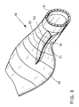
- FIG. 3 a perspective view of an inner region of a rotor blade 60 is shown in a perspective view.
- the rotor blade 60 has a circular rotor blade connection 61.
- the attachment body 51 which faces away from the leading edge, adjoins the attachment body 51 in the manner of a spoiler on the pressure side of the rotor blade 60.
- the attachment body 51 has a Aufsatzanström nature 52, wherein at the transition from the normal flow surface of the rotor blade 60 to Aufsatzanström preparation 52, the corresponding Aufus the profiles are.
- the drawn line 53 thus forms a kind of connecting line of Auf.
- the attachment inflow surface 52 of the attachment device 51 is bounded by the connection line 54 of the attachment inflow surface 52.
- the connecting line 54 are the end points of the Aufsatzanström
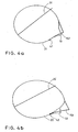
- FIGS. 4a to 4d are advantageous embodiments of an attachment device 51 or modified profiles Fig. 1 shown.
- the drawn profiles 21, 22, 23, 25 correspond to the in Fig. 1 shown profile sections.
- the modified profile sections 21, 22, 23, 25 have in this embodiment, a very high aerodynamic quality, so that the energy yield of a rotor blade in the inner rotor hub near range is maximized or is. This results in an optimized attachment device 151 (in comparison to the other attachment device 51 (cf. Fig. 1 or Fig. 2 ).
- FIGS. 4a to 4d the position of the Aufhow of the individual profile sections 21, 22, 24, 25 and the local direction of flow 31, 32, 33 and 35 clearly visible in this illustration.
- Fig. 4a to. 4c show very clearly that the profile contour in the case of the thick profiles in the region of the point of view 41, 42, 43 is substantially parallel to the direction of flow.
- the energy yield optimized design of the attachment device 151 has an even stronger displacement of the tear-off point away from the leading edge of the sheet than the geometry of FIGS Fig. 1 and 2 shown execution. However, the construction cost of such a Ausatzvorraum is high.
- Such an attachment device is particularly useful if rotor blades are to be improved during production, whereby no completely new rotor blade form has to be built.
- the illustrated attachment device can be easily mounted on an existing rotor blade.
- Fig. 5 shows the execution of an attachment device 51 with adhesive tabs 71, 72 in cross section on a profile.
- adhesive tabs 71, 72 With a rotor blade with a length of 37 m and a length of the attachment device of about 5.5 m, adhesive tabs 71, 72 with a width of 50 to 80 mm prove to be advantageous.
- the attachment 51 itself is made of 2 to 4 mm thick fiberglass (laminated fabric or fiber spray) manufactured. The tear-off is designed to achieve a high aerodynamic quality as sharp as possible corner.
- the unavoidable contour jump in the Auf Vietnamese 45 should be kept as small as possible, a maximum of 5 mm, in particular 2 to 3 mm in a glued attachment device 51 or glued spoiler.
- rounding with adhesive e.g., Sikaflex is beneficial.
Description
- Die Erfindung betrifft ein Rotorblatt einer Windenergieanlage mit einer Oberseite (Saugseite) und einer Unterseite (Druckseite), wobei entlang einer Längsachse zwischen einer Rotorblattwurzel und einer Rotorblattspitze Profile im Querschnitt mit einer Vorderkante und einer Hinterkante ausgebildet sind, für jedes Profil jeweils eine Auslegungsanströmrichtung vorbestimmt ist und die Profile im äußeren, der Rotorblattspitze zugewandten Bereich mit einer relativen Dicke von weniger als 30 % ausgebildet sind. Darüber hinaus betrifft die Erfindung eine Windenergieanlage sowie eine Verwendung einer Aufsatzvorrichtung. Überdies betrifft die Erfindung ein Verfahren zur Herstellung eines Rotorblatts einer Windenergieanlage.
- Der Wirkungsgrad von Rotorblättern einer Windenergieanlage wird durch den Anströmwinkel, also den Winkel zwischen der Rotorblattprofilsehne und der Anströmrichtung der Luft, bestimmt. Bei Windenergieanlagen hängt insbesondere der Anströmwinkel von der Rotorblattgeschwindigkeit und somit von der Rotordrehzahl und der Windgeschwindigkeit ab.
- Damit sich bei einem aerodynamischen Auftrieb eines Rotorblatts die Auftriebskraft voll entfalten kann, muss die Strömung des Windes möglichst lange am Profil des Rotorblatts anliegen. Hierbei sollte das Rotorblatt immer unter einem günstigen Winkel angeströmt werden. Die Größe und der Winkel der Anströmgeschwindigkeit ändern sich hierbei in Abhängigkeit der Windgeschwindigkeit und der Umlaufgeschwindigkeit im jeweiligen Punkt eines Rotorblatts. Dadurch, dass die Umfangsgeschwindigkeit an der Rotorblattspitze am größten ist und zur Rotornabe hin abnimmt, ergibt sich daraus eine Zunahme des Anströmwinkels relativ zur Rotorebene von der Blattspitze in Richtung Nabe. Um zu gewährleisten, dass das Rotorblatt an jedem Punkt optimal angeströmt wird, werden die Rotorblätter mit einer Verwindung ausgeführt.
- Rotorblätter einer Windenergieanlage sind in
DE-A-198 15 519 undDE-A-10 2004 007 487 beschrieben. Ein weiteres Rotorblatt einer Windturbine ist inWO-A-2002/008600 offenbart. - In
WO-A-2004/097215 ist ein Rotorblatt einer Windenergieanlage offenbart, wobei das Rotorblatt eine Dickenrücklage etwa im Bereich von 15% bis 40% aufweist und wobei die größte Profildicke etwa 20% bis 45% beträgt. - Darüber hinaus ist in
DK-U-9 500 009 - Ausgehend von diesem Stand der Technik besteht die Aufgabe der vorliegenden Erfindung darin, ein Rotorblatt einer Windenergieanlage bereit zu stellen sowie den Betrieb einer Windenergieanlage zu verbessern, wodurch beim Einsatz eines derartigen Rotorblatts der Energieertrag an einer Windenergieanlage optimiert bzw. erhöht wird.
- Gelöst wird diese Aufgabe bei einem Rotorblatt der eingangs genannten Art dadurch, dass entlang der Längsachse im inneren, der Rotorblattwurzel zugeordneten Bereich an Profilen mit einer relativen Dicke von mehr als 30 % auf der Druckseite eine Aufsatzvorrichtung angeordnet ist, die eine Aufsatzanströmfläche sowie einen der Vorderkante zugewandten Aufpunkt der Aufsatzanströmfläche und einen der Hinterkante zugewandten Endpunkt der Aufsatzanströmfläche aufweist, wobei der Aufpunkt der Aufsatzanströmfläche in einem Bereich zwischen der Vorderkante und der Hinterkante der Profile angeordnet ist, so dass die Tangente an das Profil im Aufpunkt in einem Winkelbereich zwischen +20° und -20°, insbesondere zwischen +15° und -15°, zur Auslegungsanströmrichtung des Profils ausgebildet ist.
- Die Erfindung beruht auf dem Gedanken, dass ein Rotorblattprofil im inneren Bereich, d.h. mit einer größeren relativen Dicke von mehr als 30 %, insbesondere mehr als 50 % relativer Dicke, durch eine zusätzlich ausgebildete Anströmfläche bzw. Aufsatzanströmfläche durch die Aufsatzvorrichtung auf der Druckseite des Rotorblatts eine optimierte aerodynamische Ausbildung erhält. Durch die zusätzlich ausgebildete Anströmfläche, die beispielsweise nachträglich nach Fertigung eines kompletten Rotorblatts auf eine bevorzugte Stelle im inneren Bereich des Rotorblatts aufgebracht wird, wird eine Art Wölbungserhöhung an den bevorzugten Profilen des Rotorblatts ausgebildet, die zu einer Auftriebserhöhung führt.
- Unter der relativen Dicke eines Rotorblattprofils wird im Allgemeinen das Verhältnis der (größten) Profildicke zur Sehnenlänge des Profils verstanden.
- Bei dickeren Profilen, bei denen üblicherweise die Strömung des Windes auf der Druckseite im Rotornaben nahen Bereich abzulösen droht, werden die Aufpunkte der Aufsatzvorrichtung in einem Bereich der Profilkontur angeordnet, bei denen die Berührenden bzw. die Tangenten im jeweiligen Aufpunkt in etwa parallel zur Anströmrichtung bzw. zur (vorbestimmten) Auslegungsanströmrichtung liegen bzw. ausgebildet sind. Dadurch sind die Aufpunkte der erfindungsgemäßen Aufsatzvorrichtung auf der Druckseite des Rotorblattprofils im inneren Bereich bei relativen Profildicken von mehr als 30 %, vorzugsweise mehr als 50 %, bestimmt bzw. gekennzeichnet. Hierbei ist eine Toleranz von etwa ± 20° zwischen der Berührenden im Aufpunkt an das Profil und der Auslegungsanströmrichtung von Vorteil bzw. möglich. Typischerweise liegen die Profile im inneren Bereich mit einer relativen Dicke von mehr als 50 % vor.
- Gemäß der Erfindung weisen die Rotorblattprofile (als Primärprofile) im Innenbereich, der in seiner Konstruktion und bei der Fertigung sehr aufwändig ist, mit der ausgebildeten bzw. angeordneten Aufsatzanströmfläche der Aufsatzvorrichtung eine Art Sekundärprofile auf, so dass die Zunahme des Anströmwinkels im Rotornaben nahen Bereich durch die zusätzlich ausgebildete Anströmfläche berücksichtigt wird und der Energieertrag damit gesteigert wird.
- Beim Übergang zwischen der druckseitigen Strömungsfläche des Rotorblatts und der anschließenden Anströmfläche der Aufsatzvorrichtung ist nach wie vor eine anliegende Strömung des Mediums bzw. Winds vorgesehen.
- Mit der erfindungsgemäßen Aufsatzvorrichtung werden die aerodynamischen Profileigenschaften eines Rotorblatts im Hinblick auf einen verbesserten Energieertrag (im jährlichen Mittel) verbessert. Gemäß der Erfindung wird der Profilauftrieb von inneren Profilschnitten für relative Profildicken von 100 % bis 30 % effektiv erhöht. Dadurch, dass die Aufsatzvorrichtung vor dem Ablösepunkt der Strömung am Profil bezogen auf die Vorderkante des Profils angeordnet ist, wird die Leistung eines Rotors im Jahresmittel bis zu 3,0 % gesteigert.
- Eine bevorzugte Ausführungsform des Rotorblatts besteht darin, dass entlang der Längsachse im inneren, der Rotorblattwurzel zugeordneten Bereich an Profilen mit einer relativen Dicke von mehr als 30 % auf der Druckseite eine Aufsatzvorrichtung, die eine Aufsatzanströmfläche sowie einen der Vorderkante zugewandten Aufpunkt der Aufsatzanströmfläche und einen der Hinterkante zugewandten Endpunkt der Aufsatzanströmfläche aufweist, angeordnet ist, wobei der Aufpunkt der Aufsatzanströmfläche vor dem Ablösepunkt der Windströmung auf der Druckseite bzw. vor dem Ablösepunkt des das Rotorblatt anströmenden Mediums auf der Druckseite ausgebildet ist. Hierdurch wird ein Strömungsabriss im zentrumsnahen Bereich des Rotorblatts auf der Druckseite vermieden oder zumindest stromabwärts verschoben.
- Gemäß der Erfindung liegt bei einer vorbestimmten Auslegungsschnelllaufzahl eine so genannte Auslegungsanströmrichtung vor, die für jedes Querschnittsprofil des Rotorblatts unterschiedlich ausgebildet ist. Die Schnelllaufzahl λ eines Rotorblatts bzw. einer Windenergieanlage ist eine wichtige Kennzahl für die Auslegung von Windenergieanlagen. Sie gibt das Verhältnis der Umfangsgeschwindigkeit des Rotors (Blattspitzengeschwindigkeit) zur Windgeschwindigkeit an. Die Schnelllaufzahl gibt an, wie schnell sich die Flügel in Relation zum Wind bewegen.
- Grundsätzlich verändern sich während des Betriebs einer Windenergieanlage die Schnelllaufzahlen in Folge der Windgeschwindigkeit und der Rotordrehzahl. Bei der Auslegungsschnelllaufzahl erreicht der Rotor einer Windenergieanlage seinen maximalen Leistungsbeiwert (fester Rotorkennwert). Daher liegt bei einer entsprechenden Auslegungsschnelllaufzahl eines Rotorblatts eine entsprechende vorbestimmte Auslegungsanströmrichtung für jedes Profil vor.
- In einer bevorzugten Weiterbildung des Rotorblatts wird vorgeschlagen, dass die Schnelllaufzahl des Rotorblatts zwischen 7 und 11 liegt.
- Darüber hinaus ist weiterhin von Vorteil, wenn die Profile im inneren Bereich eine relative Dicke von mehr als 50 % aufweisen.
- Außerdem zeichnen sich die Profile dadurch aus, dass die Tangente im Aufpunkt der Aufsatzanströmfläche im Wesentlichen parallel zur Auslegungsanströmrichtung ausgebildet ist.
- Günstig ist es ferner, wenn der Endpunkt der Aufsatzanströmfläche bezogen auf die Anströmrichtung vor der Hinterkante des Rotorblatts endet.
- Weiterhin sind insbesondere die Aufpunkte der Aufsatzanströmfläche bzw. der Aufsatzvorrichtung von innen nach außen, d.h. entlang der Längsachse, kontinuierlich verbunden. Ferner sind die Endpunkte der Aufsatzvorrichtung von innen nach außen kontinuierlich verbunden, so dass die Aufsatzvorrichtung als eine Art Bauteil oder Körper ausgebildet ist.
- Eine gekrümmte räumliche Struktur der Aufsatzvorrichtung ergibt sich, wenn sich der Abstand der Endpunkte oder der Abreißpunkte der Aufsatzanströmfläche (bzw. der Aufsatzvorrichtung) von der Vorderkante des Rotorblatts entlang der Längsachse von innen nach außen zumindest in einem Längsachsenabschnitt vergrößert. Hierdurch wird eine Art gekrümmte Aufsatzvorrichtung oder eine Art Spoilereinrichtung mit einer nach innen zurücklaufenden d.h. zur Hinterkante gebogenen Konstruktion ausgebildet, wobei die nach innen zur Hinterkante ausgebildete Krümmung der Aufsatzvorrichtung sich durch die Verdrehung der Anströmrichtung ergibt.
- Dazu ist weiter vorgesehen, dass die Aufsatzvorrichtung nach Art eines Spoilers mit einer Luftleitfläche in Form der Aufsatzanstömfläche ausgebildet ist, wodurch die Energieeffizienz des Rotorblatts im inneren Bereich gesteigert wird.
- Des Weiteren ist es von Vorteil, wenn die Aufsatzvorrichtung auf das Rotorblatt geklebt wird oder ist. Hierbei kann die Aufsatzvorrichtung nachträglich nach Herstellung des Rotorblatts im inneren Bereich auf der Druckseite angeordnet werden. Dementsprechend ist insbesondere die Aufsatzvorrichtung nachrüstbar oder nachgerüstet. In der Praxis hat dies vorteilhafterweise zur Folge, dass gar keine oder keine signifikante Erhöhung der Anlagenbelastung im Vergleich zu den Lastannahmen des Auslegungsverfahrens stattfind et.
- In einer bevorzugten Ausgestaltung ist es ferner möglich, dass die Aufsatzvorrichtung von einer Ruheposition in eine Arbeitsposition gebracht wird oder ist. Hierbei kann beispielsweise die Anströmfläche der Aufsatzvorrichtung entsprechend eingestellt oder bei entsprechender Windlast eingefahren werden, wodurch die Aufsatzanströmfläche der Aufsatzvorrichtung eng am üblichen Profil des Rotorblatts anliegt.
- Außerdem ist es in einer Weiterbildung bevorzugt, wenn der Endpunkt der Aufsatzanströmfläche als Strömungsabreißpunkt auf der Druckseite des Profils ausgebildet ist.
- Ferner wird die Aufgabe gelöst durch eine Windenergieanlage, die mit wenigstens einem Rotorblatt, wie voranstehend beschrieben, ausgerüstet ist.
- Eine weitere Lösung der Aufgabe besteht in einer Verwendung einer Aufsatzvorrichtung, die in einem inneren Bereich eines erfindungsgemäßen, voranstehend beschriebenen Rotorblatts angeordnet wird oder ist.
- Außerdem wird die Aufgabe gelöst durch ein Verfahren zur Herstellung eines Rotorblatts einer Windenergieanlage, wobei eine Aufsatzvorrichtung im inneren Bereich eines Rotorblatts angeordnet wird, so dass das Rotorblatt in einer Ausführungsform gemäß den oben genannten Möglichkeiten ausgebildet ist. Zur Vermeidung von Wiederholungen wird auf die voranstehenden Ausführungen zu dem oben beschriebenen Rotorblatt ausdrücklich verwiesen.
- Die Erfindung wird nachfolgend anhand von Ausführungsbeispielen exemplarisch beschrieben, wobei bezüglich aller im Text nicht näher erläuterten erfindungsgemäßen Einzelheiten ausdrücklich auf die Zeichnungen verwiesen wird. Es zeigen:
- Fig. 1
- überlagerte Profilschnitte eines erfindungsgemäßen Rotorblatts;
- Fig. 2
- überlagerte Profilschnitte eines weiteren erfindungsgemäßen Rotorblatts;
- Fig. 3
- eine perspektivische Darstellung eines Rotorblatts im inneren Bereich mit einer erfindungsgemäßen Aufsatzvorrichtung;
- Fig. 4a bis 4d
- jeweils Profilschnitte eines erfindungsgemäßen Rotorblatts und
- Fig. 5
- einen Profilschnitt eines weiteren erfindungsgemäßen Rotorblatts.
- In den folgenden Figuren sind jeweils gleiche oder gleichartige Elemente bzw. entsprechende Teile mit denselben Bezugsziffern versehen, so dass von einer entsprechenden erneuten Vorstellung abgesehen wird.
- In
Fig. 1 sind mehrere überlagerte Profilschnitte 21, 22, 23, 24, 25 eines Rotorblatts 60 (vgl.Fig. 3 ) von der Rotorblattwurzel in inneren Bereich zum äußeren Bereich dargestellt. Das innerste Profil 21 weist in diesem Beispiel die größte relative Dicke aus. Das Profil 25 ist mit einer relativen Dicke von 45 % das dünnste Profil im inneren Bereich. Die überlagerten Profilschnitte 21, 22, 23, 24, 25 geben einen Profilverlauf eines Rotorblatts in verschiedenen Abschnitten wieder. Aus Gründen der Übersichtlichkeit wurde von der Darstellung von Profilen mit einer relativen Dicke von weniger als 30 % im äußeren Bereich abgesehen. - Darüber hinaus ist in
Fig. 1 mit dem Bezugszeichen 11 die Rotorebene in einer vorbestimmten Betriebsstellung des Rotorblatts eingezeichnet. Die verschiedenen Profilschnitte 21, 22, 23, 24, 25 sind entlang einer Auffädelachse von der Rotorblattwurzel nach außen zur Rotorblattspitze aufgefädelt. - Aus
Fig. 1 geht hervor, dass die relative Dicke der Profilschnitte 21 bis 25 von innen (Profil 21) nach außen (Profil 25) abnimmt. Das heißt, dass das Profil 21 im inneren Bereich näher an der Rotorblattwurzel als die nachfolgenden Profilschnitte 22 bis 25 angeordnet ist. - Entsprechend zum (inneren) Profilschnitt 21 ist in
Fig. 1 die dazugehörige vorbestimmte Auslegungsanströmrichtung 31 eingezeichnet. Darüber hinaus sind für die Profile 23, 25 die entsprechenden jeweiligen Auslegungsanströmrichtungen 33, 35 eingezeichnet. Überdies sind inFig. 1 für die Profilschnitte 21, 22, 23 jeweils die Aufpunkte 41, 42, 43 eines erfindungsgemäßen Aufsatzkörpers 51 als Aufsatzvorrichtung auf der Druckseite der Profile 21 bis 25 im Querschnitt dargestellt. - In
Fig. 1 sind die Querschnitte des Aufsatzkörpers 51 an den jeweiligen Profilschnitten 21 bis 25 eingezeichnet, wobei der Querschnitt des Aufsatzkörpers 51 an den Profilschnitten 21 bis 25 jeweils nach Art eines Dreiecks oder dergleichen oder annähernd dreiecksförmig ausgebildet ist. - Der entsprechende Aufpunkt 41 bis 43 des Aufsatzkörpers 51 an den jeweiligen Profilen 21 bis 23 ist beispielsweise dadurch bestimmt, dass die Berührende im Aufpunkt 41 bis 43, d.h. die Tangente an das jeweilige Profil parallel oder mit einer geringen Neigung von ± 20°, insbesondere ± 15°, zur jeweiligen Auslegungsanströmrichtung 31, 33 und 35 des dazugehörigen Profilschnitts 21, 23 sowie 25 ausgebildet ist. Hierbei ist der Aufpunkt 41 bis 43 an dem Profil 21 bis 23 vor dem jeweiligen druckseitigen Strömungsabrisspunkt des entsprechenden Profils 21 bis 23 angeordnet.
- Durch den nachträglich aufgebrachten bzw. nachrüstbaren Aufsatzkörper 51 werden die Profileigenschaften des Rotorblatts 60 im inneren Bereich, d.h. im Bereich mit einer Profildicke von mehr als 30 %, insbesondere 50 %, verbessert, da mit dem Aufsatzkörper 51 eine Wölbungserhöhung auf der Druckseite des Rotorblatts 60 ausgebildet wird. Bevor die Strömung auf der Druckseite der Profile 21 bis 23 sich ablöst, wird durch die Aufsatzvorrichtung 51 auf der Druckseite eine Aufsatzanströmfläche (vgl.
Fig. 3 , Bezugszeichen 52) der Aufsatzvorrichtung bzw. des Aufsatzkörpers 51 ausgebildet, wodurch der Profilauftrieb des Rotorblatts im inneren Bereich und damit der Energieertrag verbessert werden. Ein etwas vergrößerter Profilwiderstand durch ein vergrößertes Totwassergebiet wird hierbei in Kauf genommen bzw. toleriert. - Aus den Profilschnitten 21 bis 25 geht ferner hervor, dass die Position des Aufsatzkörpers 51 mit seinen entsprechenden Aufpunkte 41 bis 43 sich von Profil zu Profil unterscheidet bzw. verändert, so dass zunächst im inneren Profilschnitt 21 zum nächsten benachbarten Profilschnitt 22 der Aufpunkt 41 in der Projektion entlang der Auffädelachse hinter dem Aufpunkt 42 des nachfolgenden äußeren Profilschnitts 22 liegt.
- Mit zunehmendem Rotorblattradius liegen die Aufpunkte 43 und die weiteren Aufpunkte, die aus Gründen der Übersichtlichkeit nicht bezeichnet sind, zunehmend mehr von der vorderen Profilkante entfernt. Das heißt, dass der Abstand zwischen den Aufpunkten 42, 43 und den weiter außen liegenden Aufpunkten und der Vorderkante des entsprechenden Profils sich vergrößert.
- Darüber hinaus vergrößert sich die Winkelposition der Aufpunkte 41, 42, 43 mit größer werdendem Rotorradius, wobei die Winkelpositionen bezogen auf die Rotorblattebene um die Rotorblattlängsachse gemessen werden.
- Die Länge der Aufsatzvorrichtung 51 entlang der Auffädelachse oder einer anderen vorbestimmten Achse wird in Abhängigkeit der Länge des Rotorblatts festgelegt. Je nach Schlankheit des Rotorblattes kann die Länge der Aufsatzvorrichtung etwa 15% bis 25% der Rotorblattlänge betragen. Das bedeutet, dass bei einer Windenergieanlage mit einer Leistung von 1,5 MW und einer Rotorblattlänge von 37 m die Länge der Aufsatzvorrichtung beispielsweise 5,5 m beträgt, bei einer Windenergieanlage mit einer Leistung von 2 MW und einer Rotorblattlänge von 45 m die Länge der Aufsatzvorrichtung beispielsweise 7 m beträgt und bei einer Windenergieanlage mit einer Leistung von 5 MW und einer Rotorblattlänge von 61 m sowie einer schlanken Blattgeometrie die Länge der Aufsatzvorrichtung beispielsweise 15,5 m (bei relativ dicken Profilen) beträgt.
- Die Querschnittsform der Aufsatzvorrichtung 51 ist dabei nicht entscheidend, die Dreiecksform ist insbesondere aus strukturellen Gründen besonders vorteilhaft. Bei bekannten Windenergieanlagen mit bereits installierten Rotorblättern ist die Aufsatzvorrichtung 51 nachrüstbar, da in der Praxis keine Erhöhung der Anlagenbelastung im Vergleich zu den hohen Lastannahmen des Auslegungsverfahrens entsteht.
- Hierbei liegt die Erkenntnis zugrunde, dass die mit einfachen Berechnungsverfahren vorhergesagten sowie theoretisch ermittelten Auftriebsbeiwerte im Rotorblattinnenbereich real nicht erreicht werden. Mit der erfindungsgemäßen Aufsatzvorrichtung werden die Profileigenschaften eines Rotorblatts so verbessert, dass die ursprünglichen Annahmen auch in der Praxis erreicht werden.
- Die Geometrie einer vorteilhaften Positionierung der Aufsatzvorrichtung 51 ist beispielhaft für ein Rotorblatt mit einer Länge von 37 m in der
Figur 1 gezeigt. Neben den Auslegungsanströmrichtungen für einen Radius (von der Rotornabe) von 2.8 m (Profil 21), 4 m (Profil 22), 5 m (Profil 23), 6 m (Profil 24) und 7 m (Profil 25) ist auch die Rotorebene 11 eingetragen. - Es ist zu erkennen, dass die Position der Aufsatzvorrichtung 51 mit zunehmendem Rotorradius von der Blattvorderkante weg nach hinten wandert. Der absolute Abstand des Abreißpunktes als Referenzpunkt der Aufsatzvorrichtung 51 zur jeweiligen Blattvorderkante vergrößert sich. Eine Ausnahme bildet lediglich der innerste Profilschnitt 21 bei einem Radius vom 2.8 m.
- Bezogen auf die Rotorblattebene 11 ergeben sich folgende Winkelpositionen der Aufsatzvorrichtung gemessen um die Rotorblattlängsachse:
Profil Radius [m] relative Blattlänge [%] Winkelposition Aufsatzvorrichtung 21 2,8 8 169° 22 4 11 162° 23 5 13,5 167° 24 6 16 174° 25 7 19 180° - Es ist zu erkennen, dass für die inneren Profile ab einem vorbestimmten Profil die Winkelposition der Aufsatzvorrichtung mit größer werdendem Rotorradius zunimmt. Beim Übergang von dem innersten Profil 21 (Radius 2.8 m) zum nächsten Profil 22 (Radius 4 m) nimmt die Winkelposition der Aufsatzvorrichtung 51 leicht ab.
- In
Fig. 2 ist eine weitere bevorzugte Ausführungsform für ein Rotorblatt dargestellt, bei der die Profile 21 bis 25 asymmetrisch auf der Blattlängsachse bzw. Auffädelachse angeordnet sind. Hierdurch wird der Blattfreigang vor einem Turm einer Windenergieanlage entsprechend vergrößert. Die entsprechenden Auslegungsanströmrichtungen 31 bis 35 sind zu den zugehörigen Profilschnitten 21 bis 25 ebenfalls jeweils eingezeichnet. - Die Höhe der Aufsatzvorrichtung 51 beträgt in den Ausführungsbeispielen in
Fig. 1 undFig. 2 im Kreiszylinderbereich des Rotorblatts ca. 10 % des Zylinderdurchmessers, im Bereich einer Profildicke von 45 % ca. 8 % der Profildicke. Mit größerer Höhe der Aufsatzvorrichtung 51 wird die aerodynamische Wirksamkeit zunehmen, wobei bei den Ausführungsformen darauf zu achten ist, dass ein guter Kompromiss für den Bauaufwand für eine zusätzliche Aufsatzvorrichtung 51 und die Zusatzbelastung für ein Rotorblatt sowie die damit zu erzielende Ertragssteigerung erreicht wird. - In den Ausführungsbeispielen in
Fig. 1 und2 ist erkennbar, dass die Aufsatzvorrichtung 51 im inneren bereich (Profil 21) zur Hinterkante des Profils zurück läuft. Da im inneren Bereich die Anströmung stark dreht, wird der Kreiszylinder des Rotorblatts mit der Aufsatzvorrichtung 51 ebenfalls entgegen dem Uhrzeigersinn gedreht, wodurch die Position der Aufsatzvorrichtung 51 nach oben wandert. Durch diese Rückdrehung ergibt sich eine insgesamt gebogene oder gekrümmte Form der Aufsatzvorrichtung 51 entlang der Auffädelachse des Rotorblatts. - Alternativ sieht eine bevorzugte Ausführungsform vor, auf das Rückdrehen der Aufsatzvorrichtung im Innenbereich zu verzichten. Dies ist hinsichtlich des Energieertrags geringfügig schlechter, ermöglicht aber eine sehr einfache, im Wesentlichen gerade Geometrie der Aufsatzvorrichtung und somit eine einfache Bauausführung.
- Dadurch, dass durch die Aufsatzvorrichtung 51 eine Aufsatzanströmfläche im inneren Bereich eines Rotorblatts vorliegt, wird die Effizienz des Rotorblatts in der Nähe des Rotorblattsanschlusses in seiner Energieausbeute gesteigert. Hierdurch wird eine energieertragsoptimierte Ausführung eines Rotorblatts ermöglicht. Beispielsweise kann die Aufsatzvorrichtung 51 in Form eines Spoilers bei der Herstellung der Rotorblätter angeordnet werden, so dass keine komplette Änderung des Herstellungsvorgangs eines Rotorblatts durchgeführt werden muss.
- Als geeignetes Material zur Herstellung einer Aufsatzvorrichtung 51 eignet sich beispielsweise glasfaserverstärkter Kunststoff (GFK). Im Abreißpunkt, d.h. am Endpunkt der Anströmfläche bzw. der Aufsatzanströmfläche der Aufsatzvorrichtung 51 ist bevorzugt, eine scharfe Kante als Endkante auszubilden. An der Innenseite im Bereich der scharfen Endpunkte der Aufsatzvorrichtung 51 im Bereich der Endkante ist die Ecke aus Festigkeitsgründen vorteilhafterweise abgerundet. Dadurch ergibt sich an der Aufsatzvorrichtung eine sehr hohe Festigkeit bei einem geringen Gewicht der Aufsatzvorrichtung.
- Hierbei ist es von Vorteil, wenn die Aufsatzvorrichtung 51 in Richtung der Blattlängsachse vergleichsweise elastisch ausgeführt ist, d.h., dass dadurch sehr hohe Dehnungen in Längsrichtung in einem Toleranzbereich liegen.
- In weiteren Ausführungsformen ist vorgesehen, dass die Aufsatzvorrichtung in eine Arbeitsposition gebracht wird. Hierbei ist die Aufsatzvorrichtung aktivierbar ausgebildet, um bei Windgeschwindigkeiten unterhalb der Nenngeschwindigkeit bei eingeschalteter oder zugeschalteter Aufsatzvorrichtung 51 den Energieertrag zu steigern. Bei hohen Windgeschwindigkeiten wird durch Einklappen bzw. Einfahren oder Abschalten der Aufsatzanströmfläche bzw. der Aufsatzvorrichtung 51 die Belastung des Rotorblatts reduziert, indem die Aufsatzanströmfläche eng am normalen Rotorblattprofil anliegt.
- Insbesondere eignet sich zum Einschalten bzw. Zuschalten der Aufsatzvorrichtung ein Luftsack im Innern der Vorrichtung, wodurch das innere Volumen der Aufsatzvorrichtung verringert oder vergrößert wird, so dass sich unterschiedliche Anstellwinkel der Aufsatzvorrichtung 51 in Bezug auf die Druckseite des Rotorblatts ergeben. Insbesondere wird durch den Luftsack oder eine andere schaltbare Einrichtung die Aufsatzvorrichtung 51 von einer Ruheposition in eine Arbeitsposition gebracht, wobei dieser Vorgang reversibel ausgebildet ist.
- In
Fig. 3 ist ferner eine perspektivische Ansicht eines inneren Bereichs eines Rotorblatts 60 in einer perspektivischen Darstellung dargestellt. Das Rotorblatt 60 verfügt über einen kreisförmigen Rotorblattanschluss 61. Im Anschluss an den runden Kreisquerschnitt des Rotorblatts 60 schließt sich im Vorderkanten abgewandten Bereich der Aufsatzkörper 51 an, der nach Art eines Spoilers auf der Druckseite des Rotorblatts 60 angeordnet ist. - Auf der Rückseite des Rotorblatts 60 setzt oberhalb des Rotorblattanschlusses 61 die Hinterkante 62 an. Der Aufsatzkörper 51 verfügt über eine Aufsatzanströmfläche 52, wobei beim Übergang von der normalen Strömungsfläche des Rotorblatts 60 zur Aufsatzanströmfläche 52 die entsprechenden Aufpunkte der Profile liegen. Die eingezeichnete Linie 53 bildet somit eine Art Verbindungslinie der Aufpunkte. Die Aufsatzanströmfläche 52 der Aufsatzvorrichtung 51 wird durch die Verbindungslinie 54 der Aufsatzanströmfläche 52 begrenzt. Entlang der Verbindungslinie 54 sind die Endpunkte der Aufsatzanströmfläche 52.
- In den
Figuren 4a bis 4d sind vorteilhafte Ausbildungsformen einer Aufsatzvorrichtung 51 bzw. modifizierte Profile ausFig. 1 gezeigt. Die eingezeichneten Profile 21, 22, 23, 25 entsprechen dabei den inFig. 1 gezeigten Profilschnitten. Die modifizierten Profilschnitte 21, 22, 23, 25 weisen in diesem Ausführungsbeispiel eine sehr hohe aerodynamischer Güte auf, so dass die Energieausbeute eines Rotorblatts im inneren Rotornaben nahen Bereich maximiert wird oder ist. Hierdurch ergibt sich im Hinblick auf den erzielbaren zusätzlichen Energieertrag eine optimierte Aufsatzvorrichtung 151 (im Vergleich zu der anderen Aufsatzvorrichtung 51 (vgl.Fig. 1 oderFig. 2 ). - Es ist in den
Figuren 4a bis 4d jeweils in dieser Darstellung die Lage der Aufpunkte der einzelnen Profilschnitte 21, 22, 24, 25 sowie die lokale Anströmrichtung 31, 32, 33 und 35 gut zu erkennen.Fig. 4a bis. 4c zeigen sehr deutlich, dass die Profilkontur bei den dicken Profilen im Bereich des Aufpunkts 41, 42, 43 im Wesentlichen parallel zur Anströmrichtung liegt. - Nur der ganz außen liegende Profilschnitt 25 in
Fig. 4d zeigt eine schon etwas größere Abweichung der Profilkontur im Aufpunkt 45 von der Anströmrichtung (ca. 12°). Das dort im Außenbereich der Aufsatzvorrichtung 151 liegende, schon etwas dünnere Profil ermöglicht der Strömung bereits einen geringen Druckanstieg durch eine zurücklaufende Profilkontur zu ertragen. Hierdurch ist erst kurz vor dem potentiellen Abreißpunkt der Aufpunkt 45 der Aufsatzvorrichtung 151 positioniert, wobei die Profilkontur durch die Aufsatzvorrichtung 151 nach außen gezogen wird, so dass die Strömung erst wesentlich weiter hinten am Abreißpunkt der Aussatzvorrichtung 151 abreißt. - Die energieertragsoptimierte Ausführung der Aufsatzvorrichtung 151 weist eine noch stärkere Verschiebung des Abreißpunktes von der Blattvorderkante weg auf als die Geometrie der in
Fig. 1 und2 gezeigten Ausführung. Allerdings ist der Bauaufwand für eine derartige Ausatzvorrichtung hoch. - Eine derartige Aufsatzvorrichtung ist insbesondere dann sehr sinnvoll, wenn Rotorblätter gleich bei der Herstellung verbessert werden sollen, wobei keine komplett neue Rotorblattform gebaut werden muss. Die dargestellte Aufsatzvorrichtung kann auf einfache Weise an einem vorhandenen Rotorblatt montiert werden.
-
Fig. 5 zeigt die Ausführung einer Aufsatzvorrichtung 51 mit Klebelaschen 71, 72 im Querschnitt an einem Profil. Bei einem Rotorblatt mit einer Länge von 37 m und einer Länge der Aufsatzvorrichtung von etwa 5,5 m erweisen sich Klebelaschen 71, 72 mit einer Breite von 50 bis 80 mm als vorteilhaft. Die Aufsatzvorrichtung 51 selbst ist aus 2 bis 4 mm dickem GFK (laminiertes Gewebe oder Faserspritz) gefertigt. Der Abreißpunkt ist zur Erzielung einer hohen aerodynamischen Güte als möglichst scharfe Ecke ausgeführt. - Der bei einer aufgeklebten Aufsatzvorrichtung 51 bzw. aufgeklebten Spoiler unvermeidliche Kontursprung im Aufpunkt 45 sollte möglichst klein gehalten werden, maximal 5 mm, insbesondere 2 bis 3 mm. Zur Widerstandsregulierung ist eine Ausrundung mit Klebemasse (z.B. Sikaflex) von Vorteil.
- In der Innenkontur wird diese Ecke aus Festigkeitsgründen vorteilhaft etwas ausgerundet. Durch den Dreiecksquerschnitt ergibt sich für die aufgeklebte Aufsatzvorrichtung 51 eine sehr hohe Festigkeit bei geringem Gewicht.
-
11 Rotorebene 21 Profil 22 Profil 23 Profil 24 Profil 25 Profil 31 Auslegungsanströmrichtung 32 Auslegungsanströmrichtung 33 Auslegungsanströmrichtung 41 Aufpunkt 42 Aufpunkt 43 Aufpunkt 51 Aufsatzvorrichtung 52 Aufsatzanströmfläche 53 Linie 54 Verbindungslinie 60 Rotorblatt 61 Rotorblattanschluss 62 Hinterkante 71 Klebelasche 72 Klebelasche 151 Aufsatzvorrichtung
Claims (15)
- Rotorblatt (60) einer Windenergieanlage mit einer Oberseite (Saugseite) und einer Unterseite (Druckseite), wobei entlang einer Längsachse zwischen einer Rotorblattwurzel und einer Rotorblattspitze Profile (21, 22, 23, 24, 25) im Querschnitt mit einer Vorderkante und einer Hinterkante (62) ausgebildet sind, für jedes Profil (21, 22, 23, 24, 25) jeweils eine Auslegungsanströmrichtung (31, 32, 33, 34, 35) vorbestimmt ist und die Profile (21, 22, 23, 24, 25) im äußeren, der Rotorblattspitze zugewandten Bereich mit einer relativen Dicke von weniger als 30 % ausgebildet sind, dadurch gekennzeichnet, dass entlang der Längsachse im inneren, der Rotorblattwurzel zugeordneten Bereich an Profilen (21, 22, 23, 24, 25) mit einer relativen Dicke von mehr als 30 % auf der Druckseite eine Aufsatzvorrichtung (51), die eine Aufsatzanströmfläche (52) sowie einen der Vorderkante zugewandten Aufpunkt (41, 42, 43) der Aufsatzanströmfläche (52) und einen der Hinterkante (62) zugewandten Endpunkt der Aufsatzanströmfläche (52) aufweist, angeordnet ist, wobei der Aufpunkt (41, 42, 43) der Aufsatzanströmfläche (52) in einem Bereich zwischen der Vorderkante und der Hinterkante (62) der Profile (21, 22, 23, 24, 25) angeordnet ist, so dass die Tangente an das Profil (21, 22, 23, 24, 25) im Aufpunkt (41, 42, 43) in einem Winkelbereich zwischen +20° und -20°, insbesondere zwischen +15° und -15°, zur Auslegungsanströmrichtung (31, 32, 33, 34, 35) des Profils (21, 22, 23, 24, 25) ausgebildet ist.
- Rotorblatt (60) nach Anspruch 1, dadurch gekennzeichnet, dass entlang der Längsachse im inneren, der Rotorblattwurzel zugeordneten Bereich an Profilen (21, 22, 23, 24, 25) mit einer relativen Dicke von mehr als 30 % auf der Druckseite eine Aufsatzvorrichtung (51), die eine Aufsatzanströmfläche (52) sowie einen der Vorderkante zugewandten Aufpunkt der Aufsatzanströmfläche (52) und einen der Hinterkante (62) zugewandten Endpunkt der Aufsatzanströmfläche (52) aufweist, angeordnet ist, wobei der Aufpunkt der Aufsatzanströmfläche (52) vor dem Ablösepunkt des das Rotorblatt (60) anströmenden Mediums auf der Druckseite ausgebildet ist.
- Rotorblatt (60) nach Anspruch 1 oder 2, dadurch gekennzeichnet, dass die Tangente im Aufpunkt (41, 42, 43) im Wesentlichen parallel zur Auslegungsanströmrichtung (31, 32, 33, 34, 35) ausgebildet ist.
- Rotorblatt (60) nach einem der Ansprüche 1 bis 3, dadurch gekennzeichnet, dass der Endpunkt der Aufsatzanströmfläche (52) vor der Hinterkante endet.
- Rotorblatt (60) nach einem der Ansprüche 1 bis 4, dadurch gekennzeichnet, dass die Aufpunkte (53) der Aufsatzanströmfläche (52) von innen nach außen kontinuierlich verbunden sind.
- Rotorblatt (60) nach einem der Ansprüche 1 bis 5, dadurch gekennzeichnet, dass die Endpunkte (54) der Aufsatzanströmfläche (52) von innen nach außen kontinuierlich verbunden sind.
- Rotorblatt (60) nach einem der Ansprüche 1 bis 6, dadurch gekennzeichnet, dass der Abstand der Endpunkte (54) der Aufsatzanströmfläche (52) von der Vorderkante des Rotorblatts (60) entlang der Längsachse von innen nach außen sich vergrößert.
- Rotorblatt (60) nach einem der Ansprüche 1 bis 7, dadurch gekennzeichnet, dass die Aufsatzvorrichtung (51) nach Art eines Spoilers (51) ausgebildet ist.
- Rotorblatt (60) nach einem der Ansprüche 1 bis 8, dadurch gekennzeichnet, dass die Aufsatzvorrichtung (51) auf das Rotorblatt (60) geklebt wird oder ist.
- Rotorblatt (60) nach einem der Ansprüche 1 bis 9, dadurch gekennzeichnet, dass die Aufsatzvorrichtung (51) nachrüstbar oder nachgerüstet ist.
- Rotorblatt (60) nach einem der Ansprüche 1 bis 10, dadurch gekennzeichnet, dass die Aufsatzvorrichtung (51) von einer Ruheposition in eine Arbeitsposition gebracht wird oder ist.
- Rotorblatt (60) nach einem der Ansprüche 1 bis 11, dadurch gekennzeichnet, dass der Endpunkt der Aufsatzanströmfläche (52) als Strömungsabreißpunkt ausgebildet ist.
- Windenergieanlage mit wenigstens einem Rotorblatt (60) nach einem der Ansprüche 1 bis 12.
- Verwendung einer Aufsatzvorrichtung (51), die in einem inneren Bereich eines Rotorblatts (60) nach einem der Ansprüche 1 bis 12 angeordnet wird oder ist.
- Verfahren zur Herstellung eines Rotorblatts (60) einer Windenergieanlage, wobei eine Aufsatzvorrichtung (51) im inneren Bereich des Rotorblatts (60) angeordnet wird, so dass das Rotorblatt (60) nach einem der Ansprüche 1 bis 12 ausgebildet wird.
Applications Claiming Priority (2)
| Application Number | Priority Date | Filing Date | Title |
|---|---|---|---|
| DE102006017897A DE102006017897B4 (de) | 2006-04-13 | 2006-04-13 | Rotorblatt einer Windenergieanlage |
| PCT/EP2007/002735 WO2007118581A1 (de) | 2006-04-13 | 2007-03-28 | Rotorblatt einer windenergieanlage |
Publications (2)
| Publication Number | Publication Date |
|---|---|
| EP2004990A1 EP2004990A1 (de) | 2008-12-24 |
| EP2004990B1 true EP2004990B1 (de) | 2013-05-15 |
Family
ID=38180302
Family Applications (1)
| Application Number | Title | Priority Date | Filing Date |
|---|---|---|---|
| EP07723681.8A Revoked EP2004990B1 (de) | 2006-04-13 | 2007-03-28 | Rotorblatt einer windenergieanlage |
Country Status (8)
| Country | Link |
|---|---|
| US (1) | US8052394B2 (de) |
| EP (1) | EP2004990B1 (de) |
| CN (1) | CN101711308B (de) |
| CA (1) | CA2642840C (de) |
| DE (1) | DE102006017897B4 (de) |
| DK (1) | DK2004990T3 (de) |
| ES (1) | ES2414459T3 (de) |
| WO (1) | WO2007118581A1 (de) |
Families Citing this family (62)
| Publication number | Priority date | Publication date | Assignee | Title |
|---|---|---|---|---|
| US7517198B2 (en) | 2006-03-20 | 2009-04-14 | Modular Wind Energy, Inc. | Lightweight composite truss wind turbine blade |
| DE102007006643A1 (de) * | 2007-02-06 | 2008-08-07 | Daubner & Stommel GbR Bau-Werk-Planung (vertretungsberechtigter Gesellschafter: Matthias Stommel, 27777 Ganderkesee) | Nachrüstteil für ein Rotorblatt einer Windenergieanlage |
| EP2031242A1 (de) * | 2007-08-29 | 2009-03-04 | Lm Glasfiber A/S | Rotorblattelement zur Montage auf einem Blatt einer Windturbine und Verfahren zur Änderung des aerodynamischen Profils eines Rotorblattes |
| ES2320962B1 (es) * | 2007-11-28 | 2010-03-11 | GAMESA INNOVATION & TECHNOLOGY S.L. | Perfil aerodinamico para la raiz de una pala de aerogenerador con doble borde de ataque. |
| DE102008026474A1 (de) * | 2008-06-03 | 2009-12-10 | Mickeler, Siegfried, Prof. Dr.-Ing. | Rotorblatt für eine Windkraftanlage sowie Windkraftanlage |
| GB2462307A (en) | 2008-08-01 | 2010-02-03 | Vestas Wind Sys As | Extension portion for wind turbine blade |
| GB2462308A (en) * | 2008-08-01 | 2010-02-03 | Vestas Wind Sys As | Extension portion for wind turbine blade |
| ES2640228T3 (es) * | 2008-08-21 | 2017-11-02 | Lm Wind Power A/S | Sección de pala para una pala de turbina eólica |
| DE102008052858B9 (de) * | 2008-10-23 | 2014-06-12 | Senvion Se | Profil eines Rotorblatts und Rotorblatt einer Windenergieanlage |
| US7837442B2 (en) | 2008-12-03 | 2010-11-23 | General Electric Company | Root sleeve for wind turbine blade |
| EP2138714A1 (de) | 2008-12-12 | 2009-12-30 | Lm Glasfiber A/S | Windturbinenschaufel mit einer Vorrichtung zur Stromführung mit optimierter Höhe |
| EP2141358A1 (de) * | 2008-12-12 | 2010-01-06 | Lm Glasfiber A/S | Windturbinenschaufel mit einem Spoiler mit effektiver Luftstromteilung |
| EP2404055B1 (de) * | 2009-03-06 | 2016-10-12 | Vestas Wind Systems A/S | Eine erhöhte ausgangsleistung liefernde windturbine |
| US7988421B2 (en) | 2009-03-31 | 2011-08-02 | General Electric Company | Retrofit sleeve for wind turbine blade |
| EP2253834A1 (de) * | 2009-05-18 | 2010-11-24 | Lm Glasfiber A/S | Windturbinenschaufel mit Flusswechselelementen |
| EP2253838A1 (de) * | 2009-05-18 | 2010-11-24 | Lm Glasfiber A/S | Verfahren zum Betrieb einer Windkraftanlage |
| EP2253835A1 (de) * | 2009-05-18 | 2010-11-24 | Lm Glasfiber A/S | Windturbinenschaufel mit einem Basisteil mit einem nicht-positiven Sturz |
| EP2253837A1 (de) * | 2009-05-18 | 2010-11-24 | Lm Glasfiber A/S | Windturbinenschaufel mit Flusswechselelementen |
| EP2253839A1 (de) * | 2009-05-18 | 2010-11-24 | Lm Glasfiber A/S | Windturbinenschaufel mit Flusswechselelementen |
| EP2253836A1 (de) * | 2009-05-18 | 2010-11-24 | Lm Glasfiber A/S | Windturbinenblatt |
| PL2360374T3 (pl) * | 2009-10-08 | 2019-11-29 | Lm Wind Power As | Łopata turbiny wiatrowej ze skierowanym do przodu urządzeniem kierującym przepływem |
| DK2343450T3 (en) * | 2009-10-08 | 2019-04-15 | Lm Wind Power As | Wind turbine blade with longitudinal flow guiding device having a plate-shaped element. |
| PL2343451T3 (pl) | 2009-10-08 | 2018-08-31 | Lm Wind Power International Technology Ii Aps | Łopata turbiny wiatrowej z wieloma rozciągającymi się wzdłużnie częściami urządzenia do kierowania przepływem |
| EP2338668A1 (de) | 2009-12-22 | 2011-06-29 | Lm Glasfiber A/S | Verfahren zur Herstellung einer Verbundschalenstruktur |
| GB2476509A (en) * | 2009-12-24 | 2011-06-29 | Rolls Royce Plc | Turbine with reduced thrust coefficient at excessive speed |
| EP2366891B1 (de) | 2010-03-18 | 2014-07-23 | Nordex Energy GmbH | Windenergieanlagenrotorblatt |
| EP2366892B1 (de) * | 2010-03-18 | 2014-07-30 | Nordex Energy GmbH | Windenergieanlagenrotorblatt |
| DK2405129T3 (en) * | 2010-07-06 | 2017-03-13 | Lm Wp Patent Holding As | Wind turbine blade with variable rear edge |
| JP5479300B2 (ja) | 2010-10-22 | 2014-04-23 | 三菱重工業株式会社 | 風車翼およびこれを備えた風力発電装置ならびに風車翼の設計方法 |
| US8523515B2 (en) | 2010-11-15 | 2013-09-03 | General Electric Company | Noise reducer for rotor blade in wind turbine |
| DK2479423T3 (en) * | 2011-01-24 | 2018-05-28 | Siemens Ag | Wind turbine rotor blade element |
| DE102011012965B4 (de) * | 2011-03-04 | 2015-10-22 | Deutsche Windtechnik AG | Rotorblatt für Windenergieanlagen mit horizontaler Drehachse sowie Windenergieanlage mit selbigem |
| US8047784B2 (en) * | 2011-03-22 | 2011-11-01 | General Electric Company | Lift device for rotor blade in wind turbine |
| EP2514962B1 (de) * | 2011-04-19 | 2017-08-02 | Siemens Aktiengesellschaft | Spoiler für eine Windturbinenschaufel |
| EP2514961B1 (de) * | 2011-04-19 | 2017-09-13 | Siemens Aktiengesellschaft | Spoiler für ein Windturbinenblatt |
| US8414261B2 (en) | 2011-05-31 | 2013-04-09 | General Electric Company | Noise reducer for rotor blade in wind turbine |
| GB201109412D0 (en) * | 2011-06-03 | 2011-07-20 | Blade Dynamics Ltd | A wind turbine rotor |
| US8834127B2 (en) * | 2011-09-09 | 2014-09-16 | General Electric Company | Extension for rotor blade in wind turbine |
| US8430638B2 (en) | 2011-12-19 | 2013-04-30 | General Electric Company | Noise reducer for rotor blade in wind turbine |
| DK2815125T3 (en) * | 2012-02-17 | 2018-07-30 | Lm Wind Power Int Tech Ii Aps | WIND TURBINE BLADE HAVING A SHAPED STALL FENCE OR FLOW DIVERTER |
| CN104364517B (zh) | 2012-03-13 | 2017-10-24 | 柯尔顿控股有限公司 | 扭转的叶片根部 |
| EP2713044B2 (de) * | 2012-09-28 | 2022-12-07 | Siemens Gamesa Renewable Energy A/S | Windturbinenlaufschaufel |
| US9377005B2 (en) | 2013-03-15 | 2016-06-28 | General Electric Company | Airfoil modifiers for wind turbine rotor blades |
| US20150050154A1 (en) * | 2013-05-23 | 2015-02-19 | Kristian R. DIXON | Airfoil trailing edge apparatus for noise reduction |
| DE102013210901A1 (de) * | 2013-06-11 | 2014-12-11 | Wobben Properties Gmbh | Rotorblatt einer Windenergieanlage und Windenergieanlage |
| DE102014203442A1 (de) * | 2013-11-04 | 2015-05-07 | Senvion Se | Rotorblatt einer Windenergieanlage und Windenergieanlage |
| US9494134B2 (en) | 2013-11-20 | 2016-11-15 | General Electric Company | Noise reducing extension plate for rotor blade in wind turbine |
| US11143160B2 (en) * | 2014-07-14 | 2021-10-12 | Lm Wp Patent Holding A/S | Aeroshell extender piece for a wind turbine blade |
| GB201419389D0 (en) | 2014-10-31 | 2014-12-17 | Lm Wp Patent Holding As | Wind turbine blade provided with surface mounted device |
| CN107110111B (zh) | 2014-08-05 | 2020-09-01 | Lm Wp 专利控股有限公司 | 设置有表面安装装置的风力涡轮机叶片 |
| DE102014215966A1 (de) | 2014-08-12 | 2016-02-18 | Senvion Gmbh | Rotorblattverlängerungskörper sowie Windenergieanlage |
| CN104595110A (zh) * | 2014-12-01 | 2015-05-06 | 东方电气集团东方汽轮机有限公司 | 一种风机风轮调整装置及包含该装置的风机组 |
| US10180125B2 (en) * | 2015-04-20 | 2019-01-15 | General Electric Company | Airflow configuration for a wind turbine rotor blade |
| WO2017039666A1 (en) * | 2015-09-03 | 2017-03-09 | Siemens Aktiengesellschaft | Wind turbine blade with trailing edge tab |
| CN106545465A (zh) * | 2017-01-25 | 2017-03-29 | 北京博比风电科技有限公司 | 延迟分离尾缘叶片 |
| US10465652B2 (en) | 2017-01-26 | 2019-11-05 | General Electric Company | Vortex generators for wind turbine rotor blades having noise-reducing features |
| US20190024631A1 (en) * | 2017-07-20 | 2019-01-24 | General Electric Company | Airflow configuration for a wind turbine rotor blade |
| US11040767B2 (en) * | 2017-11-30 | 2021-06-22 | General Electric Company | Systems and methods for improved propeller design |
| US10767623B2 (en) | 2018-04-13 | 2020-09-08 | General Electric Company | Serrated noise reducer for a wind turbine rotor blade |
| US10746157B2 (en) | 2018-08-31 | 2020-08-18 | General Electric Company | Noise reducer for a wind turbine rotor blade having a cambered serration |
| EP3851667A1 (de) | 2020-01-16 | 2021-07-21 | Nordex Energy Spain, S.A.U. | Windturbinenschaufel |
| EP4008894A1 (de) | 2020-12-02 | 2022-06-08 | Siemens Gamesa Renewable Energy A/S | Rotorblatt für eine windturbine |
Family Cites Families (14)
| Publication number | Priority date | Publication date | Assignee | Title |
|---|---|---|---|---|
| CN85105039B (zh) * | 1985-06-29 | 1988-07-06 | 库斯托基金会 | 流体动力装置 |
| DK9500009U3 (da) | 1995-01-10 | 1996-04-10 | Stiesdal Bonus Energy A Henrik | Organ til forbedring af en vindmølles virkningsgrad |
| DE19815519A1 (de) * | 1998-03-31 | 1999-10-07 | Tacke Windenergie Gmbh | Rotorblatt für eine Windkraftanlage |
| NL1012949C2 (nl) * | 1999-09-01 | 2001-03-06 | Stichting Energie | Blad voor een windturbine. |
| DE50115739D1 (de) * | 1999-12-31 | 2011-01-27 | Deutsch Zentr Luft & Raumfahrt | Flügelprofil mit leistungs-steigernder Hinterkante |
| NL1015558C2 (nl) * | 2000-06-28 | 2002-01-08 | Stichting En Onderzoek Ct Nede | Blad van een windturbine. |
| WO2002038442A2 (en) * | 2000-10-10 | 2002-05-16 | The Regents Of The University Of California | Microfabricated translational stages for control of aerodynamic loading |
| DE10319246A1 (de) | 2003-04-28 | 2004-12-16 | Aloys Wobben | Rotorblatt einer Windenergieanlage |
| DK200300670A (da) | 2003-05-05 | 2004-11-06 | Lm Glasfiber As | Vindmölleving med opdriftsregulerende organer |
| DE10347802B3 (de) * | 2003-10-10 | 2005-05-19 | Repower Systems Ag | Rotorblatt für eine Windkraftanlage |
| DE102004007487A1 (de) * | 2004-02-13 | 2005-09-01 | Aloys Wobben | Rotorblatt einer Windenergieanlage |
| US7637721B2 (en) * | 2005-07-29 | 2009-12-29 | General Electric Company | Methods and apparatus for producing wind energy with reduced wind turbine noise |
| EP1845258A1 (de) | 2006-04-10 | 2007-10-17 | Siemens Aktiengesellschaft | Rotorblatt einer Windenergieanlage |
| US7918653B2 (en) * | 2007-02-07 | 2011-04-05 | General Electric Company | Rotor blade trailing edge assemby and method of use |
-
2006
- 2006-04-13 DE DE102006017897A patent/DE102006017897B4/de not_active Revoked
-
2007
- 2007-03-28 CA CA2642840A patent/CA2642840C/en active Active
- 2007-03-28 US US12/296,745 patent/US8052394B2/en not_active Expired - Fee Related
- 2007-03-28 CN CN2007800133567A patent/CN101711308B/zh not_active Expired - Fee Related
- 2007-03-28 DK DK07723681.8T patent/DK2004990T3/da active
- 2007-03-28 WO PCT/EP2007/002735 patent/WO2007118581A1/de active Application Filing
- 2007-03-28 ES ES07723681T patent/ES2414459T3/es active Active
- 2007-03-28 EP EP07723681.8A patent/EP2004990B1/de not_active Revoked
Also Published As
| Publication number | Publication date |
|---|---|
| DE102006017897B4 (de) | 2008-03-13 |
| CN101711308A (zh) | 2010-05-19 |
| EP2004990A1 (de) | 2008-12-24 |
| ES2414459T3 (es) | 2013-07-19 |
| US8052394B2 (en) | 2011-11-08 |
| DK2004990T3 (da) | 2013-08-19 |
| US20090274559A1 (en) | 2009-11-05 |
| CA2642840A1 (en) | 2007-10-25 |
| CN101711308B (zh) | 2013-03-13 |
| DE102006017897A1 (de) | 2007-10-18 |
| CA2642840C (en) | 2013-03-05 |
| WO2007118581A1 (de) | 2007-10-25 |
Similar Documents
| Publication | Publication Date | Title |
|---|---|---|
| EP2004990B1 (de) | Rotorblatt einer windenergieanlage | |
| EP1514023B1 (de) | Windenergieanlage | |
| EP2366891B1 (de) | Windenergieanlagenrotorblatt | |
| EP3008331B1 (de) | Rotorblatt einer windenergieanlage und windenergieanlage | |
| EP2258943A2 (de) | Profil eines Rotorsblatts einer Windenergieanlage | |
| EP2280163B1 (de) | Windenergieanlage sowie Rotorblatt für eine Windenergieanlage | |
| WO2005085633A1 (de) | Windkraftmaschine mit senkrechter drehachse und zentralem umlenk-körper | |
| DE19963086C1 (de) | Rotorblatt für eine Windenergieanlage | |
| EP3066337B1 (de) | Rotorblatt einer windenergieanlage und windenergieanlage | |
| EP2594784A2 (de) | Vertikalwindturbine und Rotorblatt hierfür | |
| EP2366892B1 (de) | Windenergieanlagenrotorblatt | |
| DE202016101461U1 (de) | Rotorblatt für Windenergieanlagen mit horizontaler Drehachse sowieWindenergieanlage mit selbigem | |
| DE102013206437A1 (de) | Rotorblatt einer Windenergieanlage und Windenergieanlage | |
| EP2568166B1 (de) | Windenergieanlagenrotorblatt mit einer dicken Profilhinterkante | |
| EP3399183B1 (de) | Rotorblatt einer windenergieanlage | |
| WO2009095149A2 (de) | Freistehende, tauchende energieerzeugungsanlage mit einer axialturbine | |
| EP2281743B1 (de) | Propellergondel | |
| EP2976524B1 (de) | Rotorblatt einer windenergieanlage, windenergieanlage und verfahren zum betreiben einer windenergieanlage | |
| EP2978967B1 (de) | Rotorblatt einer windenergieanlage mit winglet | |
| EP2510224A1 (de) | Turbinenblatt für eine bidirektional anströmbare wasserturbine | |
| EP3981981A1 (de) | Rotorblatt für eine windenergieanlage, windenergieanlage und verfahren zur auslegung eines rotorblatts | |
| WO2016162350A1 (de) | Windenergieanlagen-rotorblatt | |
| DE102011011084A1 (de) | Rotorblatt für eine Windenergieanlage mit einer ausfahrbaren Blattvergrößerung | |
| DE102007059285A1 (de) | Rotorblatt für Windenergieanlagen | |
| DE102022121502A1 (de) | Rotorblatt für eine Windenergieanlage sowie Rotorblattspitze |
Legal Events
| Date | Code | Title | Description |
|---|---|---|---|
| PUAI | Public reference made under article 153(3) epc to a published international application that has entered the european phase |
Free format text: ORIGINAL CODE: 0009012 |
|
| 17P | Request for examination filed |
Effective date: 20080809 |
|
| AK | Designated contracting states |
Kind code of ref document: A1 Designated state(s): AT BE BG CH CY CZ DE DK EE ES FI FR GB GR HU IE IS IT LI LT LU LV MC MT NL PL PT RO SE SI SK TR |
|
| 17Q | First examination report despatched |
Effective date: 20091208 |
|
| DAX | Request for extension of the european patent (deleted) | ||
| GRAP | Despatch of communication of intention to grant a patent |
Free format text: ORIGINAL CODE: EPIDOSNIGR1 |
|
| GRAS | Grant fee paid |
Free format text: ORIGINAL CODE: EPIDOSNIGR3 |
|
| GRAA | (expected) grant |
Free format text: ORIGINAL CODE: 0009210 |
|
| RAP1 | Party data changed (applicant data changed or rights of an application transferred) |
Owner name: REPOWER SYSTEMS SE |
|
| AK | Designated contracting states |
Kind code of ref document: B1 Designated state(s): AT BE BG CH CY CZ DE DK EE ES FI FR GB GR HU IE IS IT LI LT LU LV MC MT NL PL PT RO SE SI SK TR |
|
| REG | Reference to a national code |
Ref country code: GB Ref legal event code: FG4D Free format text: NOT ENGLISH Ref country code: CH Ref legal event code: EP |
|
| REG | Reference to a national code |
Ref country code: AT Ref legal event code: REF Ref document number: 612292 Country of ref document: AT Kind code of ref document: T Effective date: 20130615 |
|
| REG | Reference to a national code |
Ref country code: IE Ref legal event code: FG4D Free format text: LANGUAGE OF EP DOCUMENT: GERMAN |
|
| REG | Reference to a national code |
Ref country code: DE Ref legal event code: R096 Ref document number: 502007011763 Country of ref document: DE Effective date: 20130711 |
|
| REG | Reference to a national code |
Ref country code: ES Ref legal event code: FG2A Ref document number: 2414459 Country of ref document: ES Kind code of ref document: T3 Effective date: 20130719 |
|
| REG | Reference to a national code |
Ref country code: DK Ref legal event code: T3 |
|
| REG | Reference to a national code |
Ref country code: LT Ref legal event code: MG4D |
|
| REG | Reference to a national code |
Ref country code: NL Ref legal event code: VDEP Effective date: 20130515 |
|
| PG25 | Lapsed in a contracting state [announced via postgrant information from national office to epo] |
Ref country code: SI Free format text: LAPSE BECAUSE OF FAILURE TO SUBMIT A TRANSLATION OF THE DESCRIPTION OR TO PAY THE FEE WITHIN THE PRESCRIBED TIME-LIMIT Effective date: 20130515 Ref country code: LT Free format text: LAPSE BECAUSE OF FAILURE TO SUBMIT A TRANSLATION OF THE DESCRIPTION OR TO PAY THE FEE WITHIN THE PRESCRIBED TIME-LIMIT Effective date: 20130515 Ref country code: PT Free format text: LAPSE BECAUSE OF FAILURE TO SUBMIT A TRANSLATION OF THE DESCRIPTION OR TO PAY THE FEE WITHIN THE PRESCRIBED TIME-LIMIT Effective date: 20130916 Ref country code: GR Free format text: LAPSE BECAUSE OF FAILURE TO SUBMIT A TRANSLATION OF THE DESCRIPTION OR TO PAY THE FEE WITHIN THE PRESCRIBED TIME-LIMIT Effective date: 20130816 Ref country code: SE Free format text: LAPSE BECAUSE OF FAILURE TO SUBMIT A TRANSLATION OF THE DESCRIPTION OR TO PAY THE FEE WITHIN THE PRESCRIBED TIME-LIMIT Effective date: 20130515 Ref country code: FI Free format text: LAPSE BECAUSE OF FAILURE TO SUBMIT A TRANSLATION OF THE DESCRIPTION OR TO PAY THE FEE WITHIN THE PRESCRIBED TIME-LIMIT Effective date: 20130515 Ref country code: IS Free format text: LAPSE BECAUSE OF FAILURE TO SUBMIT A TRANSLATION OF THE DESCRIPTION OR TO PAY THE FEE WITHIN THE PRESCRIBED TIME-LIMIT Effective date: 20130915 |
|
| PG25 | Lapsed in a contracting state [announced via postgrant information from national office to epo] |
Ref country code: PL Free format text: LAPSE BECAUSE OF FAILURE TO SUBMIT A TRANSLATION OF THE DESCRIPTION OR TO PAY THE FEE WITHIN THE PRESCRIBED TIME-LIMIT Effective date: 20130515 Ref country code: BG Free format text: LAPSE BECAUSE OF FAILURE TO SUBMIT A TRANSLATION OF THE DESCRIPTION OR TO PAY THE FEE WITHIN THE PRESCRIBED TIME-LIMIT Effective date: 20130815 |
|
| PG25 | Lapsed in a contracting state [announced via postgrant information from national office to epo] |
Ref country code: LV Free format text: LAPSE BECAUSE OF FAILURE TO SUBMIT A TRANSLATION OF THE DESCRIPTION OR TO PAY THE FEE WITHIN THE PRESCRIBED TIME-LIMIT Effective date: 20130515 |
|
| PG25 | Lapsed in a contracting state [announced via postgrant information from national office to epo] |
Ref country code: CZ Free format text: LAPSE BECAUSE OF FAILURE TO SUBMIT A TRANSLATION OF THE DESCRIPTION OR TO PAY THE FEE WITHIN THE PRESCRIBED TIME-LIMIT Effective date: 20130515 Ref country code: SK Free format text: LAPSE BECAUSE OF FAILURE TO SUBMIT A TRANSLATION OF THE DESCRIPTION OR TO PAY THE FEE WITHIN THE PRESCRIBED TIME-LIMIT Effective date: 20130515 Ref country code: EE Free format text: LAPSE BECAUSE OF FAILURE TO SUBMIT A TRANSLATION OF THE DESCRIPTION OR TO PAY THE FEE WITHIN THE PRESCRIBED TIME-LIMIT Effective date: 20130515 |
|
| PG25 | Lapsed in a contracting state [announced via postgrant information from national office to epo] |
Ref country code: IT Free format text: LAPSE BECAUSE OF FAILURE TO SUBMIT A TRANSLATION OF THE DESCRIPTION OR TO PAY THE FEE WITHIN THE PRESCRIBED TIME-LIMIT Effective date: 20130515 Ref country code: RO Free format text: LAPSE BECAUSE OF FAILURE TO SUBMIT A TRANSLATION OF THE DESCRIPTION OR TO PAY THE FEE WITHIN THE PRESCRIBED TIME-LIMIT Effective date: 20130515 Ref country code: NL Free format text: LAPSE BECAUSE OF FAILURE TO SUBMIT A TRANSLATION OF THE DESCRIPTION OR TO PAY THE FEE WITHIN THE PRESCRIBED TIME-LIMIT Effective date: 20130515 |
|
| PLBI | Opposition filed |
Free format text: ORIGINAL CODE: 0009260 |
|
| PLAX | Notice of opposition and request to file observation + time limit sent |
Free format text: ORIGINAL CODE: EPIDOSNOBS2 |
|
| 26 | Opposition filed |
Opponent name: SIEMENS AKTIENGESELLSCHAFT Effective date: 20140217 Opponent name: LM WP PATENT HOLDING A/S Effective date: 20140214 Opponent name: VESTAS WIND SYSTEMS A/S Effective date: 20140214 |
|
| REG | Reference to a national code |
Ref country code: DE Ref legal event code: R026 Ref document number: 502007011763 Country of ref document: DE Effective date: 20140214 |
|
| PLAF | Information modified related to communication of a notice of opposition and request to file observations + time limit |
Free format text: ORIGINAL CODE: EPIDOSCOBS2 |
|
| RAP2 | Party data changed (patent owner data changed or rights of a patent transferred) |
Owner name: SENVION SE |
|
| PLBB | Reply of patent proprietor to notice(s) of opposition received |
Free format text: ORIGINAL CODE: EPIDOSNOBS3 |
|
| PG25 | Lapsed in a contracting state [announced via postgrant information from national office to epo] |
Ref country code: LU Free format text: LAPSE BECAUSE OF FAILURE TO SUBMIT A TRANSLATION OF THE DESCRIPTION OR TO PAY THE FEE WITHIN THE PRESCRIBED TIME-LIMIT Effective date: 20140328 |
|
| REG | Reference to a national code |
Ref country code: CH Ref legal event code: PL |
|
| GBPC | Gb: european patent ceased through non-payment of renewal fee |
Effective date: 20140328 |
|
| RAP2 | Party data changed (patent owner data changed or rights of a patent transferred) |
Owner name: SENVION SE |
|
| REG | Reference to a national code |
Ref country code: FR Ref legal event code: ST Effective date: 20141128 |
|
| REG | Reference to a national code |
Ref country code: IE Ref legal event code: MM4A |
|
| PG25 | Lapsed in a contracting state [announced via postgrant information from national office to epo] |
Ref country code: LI Free format text: LAPSE BECAUSE OF NON-PAYMENT OF DUE FEES Effective date: 20140331 Ref country code: IE Free format text: LAPSE BECAUSE OF NON-PAYMENT OF DUE FEES Effective date: 20140328 Ref country code: GB Free format text: LAPSE BECAUSE OF NON-PAYMENT OF DUE FEES Effective date: 20140328 Ref country code: FR Free format text: LAPSE BECAUSE OF NON-PAYMENT OF DUE FEES Effective date: 20140331 Ref country code: CH Free format text: LAPSE BECAUSE OF NON-PAYMENT OF DUE FEES Effective date: 20140331 |
|
| REG | Reference to a national code |
Ref country code: DE Ref legal event code: R082 Ref document number: 502007011763 Country of ref document: DE Representative=s name: PATENTANWAELTE SEEMANN & PARTNER, DE |
|
| REG | Reference to a national code |
Ref country code: DE Ref legal event code: R082 Ref document number: 502007011763 Country of ref document: DE Representative=s name: PATENTANWAELTE SEEMANN & PARTNER, DE Effective date: 20150227 Ref country code: DE Ref legal event code: R081 Ref document number: 502007011763 Country of ref document: DE Owner name: SENVION SE, DE Free format text: FORMER OWNER: REPOWER SYSTEMS SE, 22297 HAMBURG, DE Effective date: 20150227 Ref country code: DE Ref legal event code: R081 Ref document number: 502007011763 Country of ref document: DE Owner name: SENVION GMBH, DE Free format text: FORMER OWNER: REPOWER SYSTEMS SE, 22297 HAMBURG, DE Effective date: 20150227 Ref country code: DE Ref legal event code: R082 Ref document number: 502007011763 Country of ref document: DE Representative=s name: WALLINGER RICKER SCHLOTTER TOSTMANN PATENT- UN, DE Effective date: 20150227 Ref country code: DE Ref legal event code: R082 Ref document number: 502007011763 Country of ref document: DE Representative=s name: SEEMANN & PARTNER PATENTANWAELTE MBB, DE Effective date: 20150227 |
|
| REG | Reference to a national code |
Ref country code: AT Ref legal event code: MM01 Ref document number: 612292 Country of ref document: AT Kind code of ref document: T Effective date: 20140328 |
|
| REG | Reference to a national code |
Ref country code: DE Ref legal event code: R082 Ref document number: 502007011763 Country of ref document: DE Representative=s name: PATENTANWAELTE SEEMANN & PARTNER, DE Ref country code: DE Ref legal event code: R081 Ref document number: 502007011763 Country of ref document: DE Owner name: SENVION GMBH, DE Free format text: FORMER OWNER: SENVION SE, 22297 HAMBURG, DE Ref country code: DE Ref legal event code: R082 Ref document number: 502007011763 Country of ref document: DE Representative=s name: WALLINGER RICKER SCHLOTTER TOSTMANN PATENT- UN, DE Ref country code: DE Ref legal event code: R082 Ref document number: 502007011763 Country of ref document: DE Representative=s name: SEEMANN & PARTNER PATENTANWAELTE MBB, DE |
|
| PG25 | Lapsed in a contracting state [announced via postgrant information from national office to epo] |
Ref country code: AT Free format text: LAPSE BECAUSE OF NON-PAYMENT OF DUE FEES Effective date: 20140328 |
|
| RAP2 | Party data changed (patent owner data changed or rights of a patent transferred) |
Owner name: SENVION GMBH |
|
| PG25 | Lapsed in a contracting state [announced via postgrant information from national office to epo] |
Ref country code: MT Free format text: LAPSE BECAUSE OF FAILURE TO SUBMIT A TRANSLATION OF THE DESCRIPTION OR TO PAY THE FEE WITHIN THE PRESCRIBED TIME-LIMIT Effective date: 20130515 |
|
| PG25 | Lapsed in a contracting state [announced via postgrant information from national office to epo] |
Ref country code: MC Free format text: LAPSE BECAUSE OF FAILURE TO SUBMIT A TRANSLATION OF THE DESCRIPTION OR TO PAY THE FEE WITHIN THE PRESCRIBED TIME-LIMIT Effective date: 20130515 |
|
| PG25 | Lapsed in a contracting state [announced via postgrant information from national office to epo] |
Ref country code: CY Free format text: LAPSE BECAUSE OF FAILURE TO SUBMIT A TRANSLATION OF THE DESCRIPTION OR TO PAY THE FEE WITHIN THE PRESCRIBED TIME-LIMIT Effective date: 20130515 |
|
| PG25 | Lapsed in a contracting state [announced via postgrant information from national office to epo] |
Ref country code: HU Free format text: LAPSE BECAUSE OF FAILURE TO SUBMIT A TRANSLATION OF THE DESCRIPTION OR TO PAY THE FEE WITHIN THE PRESCRIBED TIME-LIMIT; INVALID AB INITIO Effective date: 20070328 Ref country code: TR Free format text: LAPSE BECAUSE OF FAILURE TO SUBMIT A TRANSLATION OF THE DESCRIPTION OR TO PAY THE FEE WITHIN THE PRESCRIBED TIME-LIMIT Effective date: 20130515 |
|
| PLCK | Communication despatched that opposition was rejected |
Free format text: ORIGINAL CODE: EPIDOSNREJ1 |
|
| APAW | Appeal reference deleted |
Free format text: ORIGINAL CODE: EPIDOSDREFNO |
|
| APAY | Date of receipt of notice of appeal deleted |
Free format text: ORIGINAL CODE: EPIDOSDNOA2O |
|
| APBM | Appeal reference recorded |
Free format text: ORIGINAL CODE: EPIDOSNREFNO |
|
| APBP | Date of receipt of notice of appeal recorded |
Free format text: ORIGINAL CODE: EPIDOSNNOA2O |
|
| APAH | Appeal reference modified |
Free format text: ORIGINAL CODE: EPIDOSCREFNO |
|
| APAW | Appeal reference deleted |
Free format text: ORIGINAL CODE: EPIDOSDREFNO |
|
| APAY | Date of receipt of notice of appeal deleted |
Free format text: ORIGINAL CODE: EPIDOSDNOA2O |
|
| APBM | Appeal reference recorded |
Free format text: ORIGINAL CODE: EPIDOSNREFNO |
|
| APBP | Date of receipt of notice of appeal recorded |
Free format text: ORIGINAL CODE: EPIDOSNNOA2O |
|
| APBM | Appeal reference recorded |
Free format text: ORIGINAL CODE: EPIDOSNREFNO |
|
| APBP | Date of receipt of notice of appeal recorded |
Free format text: ORIGINAL CODE: EPIDOSNNOA2O |
|
| APBQ | Date of receipt of statement of grounds of appeal recorded |
Free format text: ORIGINAL CODE: EPIDOSNNOA3O |
|
| APBQ | Date of receipt of statement of grounds of appeal recorded |
Free format text: ORIGINAL CODE: EPIDOSNNOA3O |
|
| PG25 | Lapsed in a contracting state [announced via postgrant information from national office to epo] |
Ref country code: BE Free format text: LAPSE BECAUSE OF NON-PAYMENT OF DUE FEES Effective date: 20140331 |
|
| PLAB | Opposition data, opponent's data or that of the opponent's representative modified |
Free format text: ORIGINAL CODE: 0009299OPPO |
|
| R26 | Opposition filed (corrected) |
Opponent name: SIEMENS AKTIENGESELLSCHAFT Effective date: 20140217 |
|
| PLAB | Opposition data, opponent's data or that of the opponent's representative modified |
Free format text: ORIGINAL CODE: 0009299OPPO |
|
| R26 | Opposition filed (corrected) |
Opponent name: LM WP PATENT HOLDING A/S Effective date: 20140214 |
|
| REG | Reference to a national code |
Ref country code: DE Ref legal event code: R082 Ref document number: 502007011763 Country of ref document: DE Representative=s name: WALLINGER RICKER SCHLOTTER TOSTMANN PATENT- UN, DE |
|
| PLAB | Opposition data, opponent's data or that of the opponent's representative modified |
Free format text: ORIGINAL CODE: 0009299OPPO |
|
| R26 | Opposition filed (corrected) |
Opponent name: LM WP PATENT HOLDING A/S Effective date: 20140214 |
|
| PLBP | Opposition withdrawn |
Free format text: ORIGINAL CODE: 0009264 |
|
| PGFP | Annual fee paid to national office [announced via postgrant information from national office to epo] |
Ref country code: DK Payment date: 20200323 Year of fee payment: 14 Ref country code: DE Payment date: 20200324 Year of fee payment: 14 |
|
| PGFP | Annual fee paid to national office [announced via postgrant information from national office to epo] |
Ref country code: ES Payment date: 20200421 Year of fee payment: 14 |
|
| RAP2 | Party data changed (patent owner data changed or rights of a patent transferred) |
Owner name: SENVION DEUTSCHLAND GMBH |
|
| REG | Reference to a national code |
Ref country code: DE Ref legal event code: R064 Ref document number: 502007011763 Country of ref document: DE Ref country code: DE Ref legal event code: R103 Ref document number: 502007011763 Country of ref document: DE |
|
| APBU | Appeal procedure closed |
Free format text: ORIGINAL CODE: EPIDOSNNOA9O |
|
| RDAF | Communication despatched that patent is revoked |
Free format text: ORIGINAL CODE: EPIDOSNREV1 |
|
| RDAG | Patent revoked |
Free format text: ORIGINAL CODE: 0009271 |
|
| STAA | Information on the status of an ep patent application or granted ep patent |
Free format text: STATUS: PATENT REVOKED |
|
| 27W | Patent revoked |
Effective date: 20201102 |
|
| REG | Reference to a national code |
Ref country code: FI Ref legal event code: MGE |
|
| REG | Reference to a national code |
Ref country code: AT Ref legal event code: MA03 Ref document number: 612292 Country of ref document: AT Kind code of ref document: T Effective date: 20201102 |