EP1806285B1 - Wing of composite material and method of fabricating the same - Google Patents
Wing of composite material and method of fabricating the same Download PDFInfo
- Publication number
- EP1806285B1 EP1806285B1 EP07107237A EP07107237A EP1806285B1 EP 1806285 B1 EP1806285 B1 EP 1806285B1 EP 07107237 A EP07107237 A EP 07107237A EP 07107237 A EP07107237 A EP 07107237A EP 1806285 B1 EP1806285 B1 EP 1806285B1
- Authority
- EP
- European Patent Office
- Prior art keywords
- wing
- skin
- joining
- composite material
- flat
- Prior art date
- Legal status (The legal status is an assumption and is not a legal conclusion. Google has not performed a legal analysis and makes no representation as to the accuracy of the status listed.)
- Expired - Lifetime
Links
- 239000002131 composite material Substances 0.000 title claims description 73
- 238000004519 manufacturing process Methods 0.000 title claims description 16
- 238000005304 joining Methods 0.000 claims description 72
- 238000000034 method Methods 0.000 claims description 41
- 238000003825 pressing Methods 0.000 claims description 36
- 239000000463 material Substances 0.000 claims description 7
- 239000000805 composite resin Substances 0.000 claims description 6
- 229920002379 silicone rubber Polymers 0.000 description 31
- 239000004945 silicone rubber Substances 0.000 description 29
- 229920001187 thermosetting polymer Polymers 0.000 description 23
- 238000010030 laminating Methods 0.000 description 22
- 239000011347 resin Substances 0.000 description 11
- 229920005989 resin Polymers 0.000 description 11
- 239000002313 adhesive film Substances 0.000 description 9
- 239000012530 fluid Substances 0.000 description 9
- 238000000465 moulding Methods 0.000 description 6
- 239000000853 adhesive Substances 0.000 description 4
- 230000001070 adhesive effect Effects 0.000 description 4
- 239000004744 fabric Substances 0.000 description 4
- 238000005470 impregnation Methods 0.000 description 4
- 238000009659 non-destructive testing Methods 0.000 description 4
- 230000003014 reinforcing effect Effects 0.000 description 4
- 229910000838 Al alloy Inorganic materials 0.000 description 3
- 239000007787 solid Substances 0.000 description 2
- 238000004804 winding Methods 0.000 description 2
- 239000002759 woven fabric Substances 0.000 description 2
- 229910000640 Fe alloy Inorganic materials 0.000 description 1
- 229910001069 Ti alloy Inorganic materials 0.000 description 1
- 239000004918 carbon fiber reinforced polymer Substances 0.000 description 1
- 239000003795 chemical substances by application Substances 0.000 description 1
- 238000005520 cutting process Methods 0.000 description 1
- 230000001419 dependent effect Effects 0.000 description 1
- 238000009658 destructive testing Methods 0.000 description 1
- 229920001971 elastomer Polymers 0.000 description 1
- 230000002708 enhancing effect Effects 0.000 description 1
- 239000003733 fiber-reinforced composite Substances 0.000 description 1
- 238000007689 inspection Methods 0.000 description 1
- 238000012986 modification Methods 0.000 description 1
- 230000004048 modification Effects 0.000 description 1
- 239000000565 sealant Substances 0.000 description 1
- 238000007493 shaping process Methods 0.000 description 1
- 239000003351 stiffener Substances 0.000 description 1
- 238000012360 testing method Methods 0.000 description 1
Images


Classifications
-
- B—PERFORMING OPERATIONS; TRANSPORTING
- B29—WORKING OF PLASTICS; WORKING OF SUBSTANCES IN A PLASTIC STATE IN GENERAL
- B29D—PRODUCING PARTICULAR ARTICLES FROM PLASTICS OR FROM SUBSTANCES IN A PLASTIC STATE
- B29D99/00—Subject matter not provided for in other groups of this subclass
- B29D99/001—Producing wall or panel-like structures, e.g. for hulls, fuselages, or buildings
- B29D99/0014—Producing wall or panel-like structures, e.g. for hulls, fuselages, or buildings provided with ridges or ribs, e.g. joined ribs
-
- B—PERFORMING OPERATIONS; TRANSPORTING
- B64—AIRCRAFT; AVIATION; COSMONAUTICS
- B64C—AEROPLANES; HELICOPTERS
- B64C3/00—Wings
-
- B—PERFORMING OPERATIONS; TRANSPORTING
- B29—WORKING OF PLASTICS; WORKING OF SUBSTANCES IN A PLASTIC STATE IN GENERAL
- B29C—SHAPING OR JOINING OF PLASTICS; SHAPING OF MATERIAL IN A PLASTIC STATE, NOT OTHERWISE PROVIDED FOR; AFTER-TREATMENT OF THE SHAPED PRODUCTS, e.g. REPAIRING
- B29C70/00—Shaping composites, i.e. plastics material comprising reinforcements, fillers or preformed parts, e.g. inserts
- B29C70/04—Shaping composites, i.e. plastics material comprising reinforcements, fillers or preformed parts, e.g. inserts comprising reinforcements only, e.g. self-reinforcing plastics
- B29C70/28—Shaping operations therefor
- B29C70/30—Shaping by lay-up, i.e. applying fibres, tape or broadsheet on a mould, former or core; Shaping by spray-up, i.e. spraying of fibres on a mould, former or core
- B29C70/32—Shaping by lay-up, i.e. applying fibres, tape or broadsheet on a mould, former or core; Shaping by spray-up, i.e. spraying of fibres on a mould, former or core on a rotating mould, former or core
-
- B—PERFORMING OPERATIONS; TRANSPORTING
- B29—WORKING OF PLASTICS; WORKING OF SUBSTANCES IN A PLASTIC STATE IN GENERAL
- B29C—SHAPING OR JOINING OF PLASTICS; SHAPING OF MATERIAL IN A PLASTIC STATE, NOT OTHERWISE PROVIDED FOR; AFTER-TREATMENT OF THE SHAPED PRODUCTS, e.g. REPAIRING
- B29C70/00—Shaping composites, i.e. plastics material comprising reinforcements, fillers or preformed parts, e.g. inserts
- B29C70/04—Shaping composites, i.e. plastics material comprising reinforcements, fillers or preformed parts, e.g. inserts comprising reinforcements only, e.g. self-reinforcing plastics
- B29C70/28—Shaping operations therefor
- B29C70/30—Shaping by lay-up, i.e. applying fibres, tape or broadsheet on a mould, former or core; Shaping by spray-up, i.e. spraying of fibres on a mould, former or core
- B29C70/38—Automated lay-up, e.g. using robots, laying filaments according to predetermined patterns
-
- B—PERFORMING OPERATIONS; TRANSPORTING
- B29—WORKING OF PLASTICS; WORKING OF SUBSTANCES IN A PLASTIC STATE IN GENERAL
- B29C—SHAPING OR JOINING OF PLASTICS; SHAPING OF MATERIAL IN A PLASTIC STATE, NOT OTHERWISE PROVIDED FOR; AFTER-TREATMENT OF THE SHAPED PRODUCTS, e.g. REPAIRING
- B29C70/00—Shaping composites, i.e. plastics material comprising reinforcements, fillers or preformed parts, e.g. inserts
- B29C70/04—Shaping composites, i.e. plastics material comprising reinforcements, fillers or preformed parts, e.g. inserts comprising reinforcements only, e.g. self-reinforcing plastics
- B29C70/28—Shaping operations therefor
- B29C70/40—Shaping or impregnating by compression not applied
- B29C70/42—Shaping or impregnating by compression not applied for producing articles of definite length, i.e. discrete articles
- B29C70/46—Shaping or impregnating by compression not applied for producing articles of definite length, i.e. discrete articles using matched moulds, e.g. for deforming sheet moulding compounds [SMC] or prepregs
- B29C70/462—Moulding structures having an axis of symmetry or at least one channel, e.g. tubular structures, frames
-
- B—PERFORMING OPERATIONS; TRANSPORTING
- B64—AIRCRAFT; AVIATION; COSMONAUTICS
- B64C—AEROPLANES; HELICOPTERS
- B64C3/00—Wings
- B64C3/18—Spars; Ribs; Stringers
- B64C3/185—Spars
-
- B—PERFORMING OPERATIONS; TRANSPORTING
- B64—AIRCRAFT; AVIATION; COSMONAUTICS
- B64C—AEROPLANES; HELICOPTERS
- B64C3/00—Wings
- B64C3/20—Integral or sandwich constructions
-
- B—PERFORMING OPERATIONS; TRANSPORTING
- B64—AIRCRAFT; AVIATION; COSMONAUTICS
- B64F—GROUND OR AIRCRAFT-CARRIER-DECK INSTALLATIONS SPECIALLY ADAPTED FOR USE IN CONNECTION WITH AIRCRAFT; DESIGNING, MANUFACTURING, ASSEMBLING, CLEANING, MAINTAINING OR REPAIRING AIRCRAFT, NOT OTHERWISE PROVIDED FOR; HANDLING, TRANSPORTING, TESTING OR INSPECTING AIRCRAFT COMPONENTS, NOT OTHERWISE PROVIDED FOR
- B64F5/00—Designing, manufacturing, assembling, cleaning, maintaining or repairing aircraft, not otherwise provided for; Handling, transporting, testing or inspecting aircraft components, not otherwise provided for
- B64F5/10—Manufacturing or assembling aircraft, e.g. jigs therefor
-
- B—PERFORMING OPERATIONS; TRANSPORTING
- B29—WORKING OF PLASTICS; WORKING OF SUBSTANCES IN A PLASTIC STATE IN GENERAL
- B29L—INDEXING SCHEME ASSOCIATED WITH SUBCLASS B29C, RELATING TO PARTICULAR ARTICLES
- B29L2031/00—Other particular articles
- B29L2031/30—Vehicles, e.g. ships or aircraft, or body parts thereof
- B29L2031/3076—Aircrafts
- B29L2031/3085—Wings
-
- Y—GENERAL TAGGING OF NEW TECHNOLOGICAL DEVELOPMENTS; GENERAL TAGGING OF CROSS-SECTIONAL TECHNOLOGIES SPANNING OVER SEVERAL SECTIONS OF THE IPC; TECHNICAL SUBJECTS COVERED BY FORMER USPC CROSS-REFERENCE ART COLLECTIONS [XRACs] AND DIGESTS
- Y10—TECHNICAL SUBJECTS COVERED BY FORMER USPC
- Y10T—TECHNICAL SUBJECTS COVERED BY FORMER US CLASSIFICATION
- Y10T428/00—Stock material or miscellaneous articles
- Y10T428/24—Structurally defined web or sheet [e.g., overall dimension, etc.]
- Y10T428/24174—Structurally defined web or sheet [e.g., overall dimension, etc.] including sheet or component perpendicular to plane of web or sheet
-
- Y—GENERAL TAGGING OF NEW TECHNOLOGICAL DEVELOPMENTS; GENERAL TAGGING OF CROSS-SECTIONAL TECHNOLOGIES SPANNING OVER SEVERAL SECTIONS OF THE IPC; TECHNICAL SUBJECTS COVERED BY FORMER USPC CROSS-REFERENCE ART COLLECTIONS [XRACs] AND DIGESTS
- Y10—TECHNICAL SUBJECTS COVERED BY FORMER USPC
- Y10T—TECHNICAL SUBJECTS COVERED BY FORMER US CLASSIFICATION
- Y10T428/00—Stock material or miscellaneous articles
- Y10T428/24—Structurally defined web or sheet [e.g., overall dimension, etc.]
- Y10T428/24273—Structurally defined web or sheet [e.g., overall dimension, etc.] including aperture
- Y10T428/24281—Struck out portion type
- Y10T428/24289—Embedded or interlocked
Definitions
- the present invention relates to a wing of composite material for constructing an aircraft airframe and a method of fabricating the same.
- An aircraft wing of composite material is constructed by assembling a lower skin, an upper skin, spars and ribs by using assembling jigs and fastening together the lower skin, the upper skin, the spars and the ribs by using fastening means.
- an aircraft wing of composite material is constructed by forming a combined structure of composite material integrally including a lower skin (or an upper skin), spars and ribs and fastening an upper skin (or a lower skin) to the combined structure by using fastening means.
- the aircraft wing of composite material formed by fastening together the component members is a heavyweight structure comprising a large number of component parts. Since work for assembling the aircraft wing needs special assembling jigs, the aircraft wing is costly.
- the aircraft wing constructed by using the combined structure having either the lower skin or the upper skin is based on the conventional concept of structure, jigs and processes are complicated and hence the aircraft wing is costly.
- EP-A-0257148 in which a joint between a sandwich skin panel and an elongate structural frame element of an aircraft is formed using a woven fabric connector strap of substantially H-shaped cross-section formed by intersecting woven fabric webs in which each of the webs comprises a plurality of multifilament yarn strands extending side-by-side transversely to the longitudinal direction of the strap and passing directly through the intersecting web or webs, the crossing web having portions and projecting transversely from opposite sides of the two spaced upright webs of the connector.
- EP-A-0217315 discloses a wing box cover panel in which a plurality of channel-shaped members are positioned longitudinally along the inner surface of an outer skin, each member having a web and two flanges. Members are positioned laterally contiguously to each other so that, when the outer skin and the members are cured together, the webs form an inner skin portion and adjacent flanges form blade stiffeners.
- a first object of the present invention is to provide a wing of composite material having a greatly reduced number of component parts, and capable of being assembled by greatly reduced manhours and of being fabricated at a low cost, and a method of fabricating such a wing.
- Another object of the present invention to provide a wing of composite material having an improved appearance, and capable of being formed in dimensions of an improved accuracy, and a method of forming such a wing.
- a wing of composite material comprises: upper and lower skins, each of which has a root and a tip; and a plurality of intermediate spars arranged between the upper and the lower skins; wherein the plurality of intermediate spars extend from the roots to the tips of the upper and lowest skins, and are integrally formed with or adhesively bonded to the upper and the lower skins.
- the plurality of intermediate spars are provided with openings in their side walls, and reinforcing members are passed through the openings and are bonded to the upper and the lower skins and the intermediate spars.
- Two additional spars may extend from the roots to the tips, on opposite sides of the intermediate spars, and may be bonded to the upper and the lower skins.
- the wing of composite material is an aircraft main wing, and the intermediate spars extend from a wing root toward a wing tip.
- a method of fabricating a wing of composite material comprising an upper skin, a lower skin and a plurality of intermediate spars arranged side by side so as to extend from roots toward tips of the upper and the lower skins, comprises the steps of: forming through holes in side walls of the plurality of intermediate spars; disposing the plurality of intermediate spars on one of the skins so that the through holes are aligned with each other; disposing the other skin on the plurality of intermediate spars; integrally forming the plurality of intermediate spars and the skins or adhesively bonding together the plurality of intermediate spars and the skins; and passing reinforcing members through the through holes of the plurality of intermediate spars and bonding the reinforcing members to the plurality of intermediate spars and the skins.
- the step of forming through holes in side walls of the plurality of intermediate spars includes the steps of: forming portions in which any prepreg sheets are not superposed in prepreg structures by intermittently superposing prepreg sheets on a hollow heat-resistant rubber bag; closing the portions in which any prepreg sheets are not superposed with closing members; curing the prepreg structures formed by superposing prepreg sheets; and removing the closing members from the prepreg structure after curing.
- the step of forming through holes in side walls of the plurality of intermediate spars includes the steps of: winding rovings around a laminating jig to form a roving structure; cutting out portions of the roving structure formed on the laminating jig to form openings; closing the openings with closing members; impregnating the roving structure with a resin and curing the resin-impregnated roving structure; and removing the closing members from the resin-impregnated roving structure after curing.
- a wing of composite material comprises a plurality of intermediate spars of composite material each having upper and lower flanges forming sections of upper and lower skins, and a web formed integrally with and extending between the upper and lower flange; wherein the plurality of intermediate spars are united together so that surfaces of the upper and lower flanges form surfaces of the upper and the lower skin, respectively.
- Each intermediate spar having the upper and the lower flanges and the web has a U-shaped cross section, adjacent intermediate spars are united together in such a manner that outer surfaces of portions of the flanges contiguous with an outer surface of the web of one of the intermediate spars are in contact with inner surfaces of edge portions of the flanges of the other intermediate spar, and the portions of the adjacent intermediate spars in contact with each other are fastened together with fasteners.
- the wing is an aircraft main wing, and the intermediate spars extend from a wing root toward a wing tip.
- a wing of composite material comprising:
- the flat plates extended between a wing root and a wing tip.
- the number of the flat plates is at least three, and the flat plates are disposed in a parallel arrangement.
- a method of fabricating a wing of composite material comprises the steps of: forming upper and lower skins of a fiber-reinforced resin composite material having stiffening parts on inner surfaces thereof, respectively; placing the upper and the lower skin at an interval in a die; disposing flat plates between the upper and the lower skin in such a manner that upper and lower edge portions thereof face the stiffening parts, respectively; and uniting together the upper and the lower skin by adhesively bonding the upper and the lower edge portions of the flat plates to the stiffening parts.
- a method of fabricating a wing of composite material comprises the steps of:
- Fig. 1 is an exploded perspective view of a first aircraft main wing of composite material, which does not form part of the present invention.
- An aircraft main wing 1 has an upper skin 2, a lower skin 3 and a plurality of intermediate spars 4 disposed between the upper skin 2 and the lower skin 3.
- the upper skin 2, the lower skin 3 and the intermediate spars 4 are made of a fiber-reinforced resin composite material.
- the upper skin 2, the lower skin 3 and the intermediate spars 4 are united together in an integral box structure by a thermocompression process.
- the five intermediate spars 4 are arranged contiguously with respect to a front-rear direction (a direction perpendicular to a span of the aircraft main wing 1) so as to extend from a wing root toward a wing tip. Some of the five intermediate spars 5 terminate at the wing tip.
- the intermediate spares 4 can be arranged side by side so that all the intermediate spars 4 extend from the wing root to the wing tip.
- a front edge and a rear edge of the integral box structure are trimmed.
- a front spar 5 is fastened to the front edge with ordinary fasteners, and a rear spar 6 is fastened to the rear edge with ordinary fasteners.
- a plurality of stiffening ribs 7 are disposed at predetermined longitudinal positions on the main wing 1.
- Each rib 7 is formed of an upper member 7a and a lower members 7b. As shown in Fig. 2 , each rib 7 is joined to the upper skin 2, the lower skin 3 and the intermediate spars 4 to provide the main wing 1 with structural strength and ridgidity. In this arrangement, each rib 7 is split into the upper and the lower members, and the upper and the lower members are formed by molding and are
- thermosetting composite material with prepreg A first, a method of laminating thermosetting composite material with prepreg will be explained.
- a release agent is applied to the hollow bag 11.
- Prepreg sheets including resin are superposed on the hollow bag 11 put on the core 10 by a fiber-placement automatic laminating machine, so as to form a laminated prepreg structure 12 having in side walls thereof grooves 13 and openings 14 for passing ribs therethrough.
- the fiber-placement automatic laminating machine controls a laminating angle of the prepreg sheets regardless of variation of spanwise section. Portions Portions of the prepreg sheets corresponding to the groves 13 and the openings 14 may be, for example, cut out.
- prepreg sheets 21 for forming a lower skin are laminated on a lower forming die 22.
- a plurality of hollow bags 11 holding the prepreg structures 12 thereon are arranged on the laminated prepreg sheets 21 and upper skin prepreg sheets 25 are laminated on the plurality of prepreg structures 12 to form an assembly.
- Side blocks 23 having upper and lower surfaces of shapes conforming to those of the upper and the lower skins, and fairing bars 24 for holding edge portions of the wing assembly in correct shapes are applied to the assembly.
- a cowl plate 26 having a lower surface of a shape conforming to a wing surface is placed on the laminated upper skin prepreg sheets 25.
- the laminated lower skin prepreg sheets 21, the prepreg structures 12 forming the intermediate spars and covering the hollow bags 11, the laminated upper skin prepreg sheets 25, the cowl plate 26 and the fairing bars 24 are covered with a vacuum bag 27 opening into ends of inside hollows of the hollow bags 11 as shown in Fig. 5 . Gaps between the lower forming die 22 and the hollow bags 11 are sealed with sealant strips 28 and 30.
- a space covered with the vacuum bag 27 is evacuated and heat and pressure are applied to the laminated lower skin prepreg sheets 21, the prepreg structures 12 and the laminated upper skin prepreg sheets 25.
- the laminated lower skin prepreg sheets 21, the prepreg structures 12 forming the intermediate spars and the laminated upper skin prepreg sheets 25, are formed into an integral box structure, i.e., a principal part of the wing of composite material.
- the fairing bars 24 are removed from the lower forming die 22, the side blocks 23 and the hollow bags 11 are removed from the integral box structure, and the closing plugs 13a and 14a are removed from the grooves 13 and the openings 14 of the intermediate spars 4.
- the ribs 7 each capable of being split into the upper member 7a and the lower member 7b are inserted from one side of the integral box structure through the grooves 13 and the openings 14 of the intermediate spars 4 to the other side of the integral box structure.
- the ribs 7 are joined to the upper skin 2, the lower skin 3 and the intermediate spars 4 by the ordinary fasteners.
- the front edge and the rear edge of the integral box structure provided with the ribs 7 are trimmed.
- the front spar 5 and the rear spar 6 are attached to the front edge and the rear edge, respectively, of the trimmed integral box structure by ordinary fasteners to complete the wing of composite material.
- the box structure can be formed in a lightweight structure, and the number of parts can be reduced, which enables the wing to be fabricated at a reduced cost.
- thermosetting resin impregnation process A method of forming an integral box structure using a thermosetting resin impregnation process will be described with reference to Figs. 6 and 7 .
- rovings 12a of many filaments are wound in a roving structure round a laminating jig 10a of an iron alloy or a CFRP. Portions of the roving structure are cut out to form grooves 13 and openings 14 for passing ribs therethrough. The grooves 13 and the openings 14 are closed by silicone rubber plates or aluminum alloy plates.
- the laminating jig 10a is divided longitudinally obliquely into parts to facilitate removing the same from a molded structure formed thereon.
- fabrics 34 for stiffening a lower skin is superposed on a lower mold 31.
- a plurality of laminating jigs 10a each holding the roving structure formed by winding the rovings 12a thereon are arranged side by side on the superposed fabrics 34.
- Fabrics 35 for stiffening an upper skin are superposed on the roving structures held on the laminating jigs 10a, and an upper mold 32 is placed on the fabrics 35.
- the upper mold 32 and the lower mold 31 are clamped by a clamping device 33 so as to form a sealed space therein.
- a pipe 36 provided with a valve 37 is connected to the lower mold 31 so as to communicate with the sealed space.
- a pipe 38 provided with a valve 39 is connected to the upper mold 32 so as to communicate with the sealed space.
- the sealed space defined by the upper mold 32 and the lower mold 31 is evacuated through the pipe 38 connected to the upper mold 32, and a thermosetting resin is injected into the sealed space through the pipe 36 connected to the lower mold 31.
- the sealed space is evacuated through the pipe 38 connected to the upper mold 32 until the thermosetting resin injected through the pipe 36 connected to the lower mold 31 into the sealed space overflows the mold through the pipe 38 connected to the upper mold 32.
- the valve 39 on the pipe 38 is closed and the thermosetting resin is forced and pressed into the sealed space through the pipe 36 connected to the lower mold 31.
- thermosetting resin injected into the mold to complete an integral box structure, i.e., a principal part of a wing of composite material.
- the upper mold 32, the lower mold 31 and the laminating jig 10a are separated from the integral box structure and the silicone rubber plate or aluminum alloy plate are removed. Subsequently, ribs 7 each capable of being split into an upper member 7a and a lower member 7b are inserted from one side of the integral box structure through the grooves 13 and the openings 14 of intermediate spars 4 to the other side of the integral box structure. The ribs 7 are joined to an upper skin 2, a lower skin 3 and the intermediate spars 4 by the ordinary fasteners.
- the front edge and the rear edge of the integral box structure provided with the ribs 7 are trimmed.
- the front spar and the rear spar are attached to the front edge and the rear edge, respectively, of the trimmed integral box structure by ordinary fasteners to complete a wing of composite material.
- a molding method of fabricating a wing of composite material employing a co-bond molding method adhesively bonds together a cured member of a composite material and an uncured member of a composite material.
- two skins are formed beforehand, for example, by a thermosetting composite material laminating process or by a thermosetting resin impregnation process.
- intermediate spars are formed by laminating prepreg sheets on hollow bags, and the intermediate spars are placed via an adhesive on a skin placed on a lower forming die.
- the other skin is bonded to the intermediate spars with an adhesive to form an assembly. Heat and pressure are applied to the assembly for curing by a method similar to the previously described method of fabricating a wing employing the thermosetting composite material laminating method.
- the upper skin 2 and the lower skin 3 may be provided with ribs 40 at positions corresponding to vertical walls, which are formed between the contiguously arranged intermediate spars 4 and extending between the upper skin 2 and the lower skin 3.
- the skin provided with the ribs 40 is formed by laminating a plurality of prepreg sheets (each of which has a groove at an end thereof) on a plurality of segments of a lower split die having an upper surface of a shape conforming to that of a lower surface of the wing, joining the segments together, laminating additional prepreg sheets on the laminated prepreg sheets, placing an upper die having a lower surface of a shape conforming to that of an upper surface of the wing on the laminated prepreg sheets, and applying heat and pressure to the laminated prepreg sheets.
- the laminated prepreg structure 12 formed on the hollow bag 11 is split properly, for example, split into half-circular divisions and the half-circular divisions are arranged so that edge portions thereof do not overlap each other or are not in contact with each other.
- the laminated prepreg structure 12 thus formed is expanded by the hollow bag 11 that expands when a pressure is applied thereto during a molding process.
- laminated prepreg structure 12 can be firmly pressed against and bonded to the skins 2 and 3, and the adjacent intermediate spars 4 can be firmly pressed against and bonded to each other.
- the molded skins 2 and 3 provided with the ribs 40 can be individually subjected to a nondestructive test.
- nondestructive testing of portions of the wing in the vicinity of the surfaces of the wing which must be strong, can be facilitated.
- the ribs combined with the skins 2 and 3 increase the rigidity of the skins 2 and 3, the option to select portions at which the skins 2 and 3 are supported for handling the skins 2 and 3 is increased, which may facilitate work for handling the skins 2 and 3.
- the wing of composite material as described can be fabricated by a method wherein plural component members of the wing are formed individually and they are adhesively bonded together. This method is called a secondary bonding method, wherein the skins and the intermediate spars are individually formed and adhesively bonded together.
- the skins and the intermediate spars may be removed from the molds and may be subjected to a shaping process.
- the grooves and the openings can be formed in the intermediate spars after curing.
- one of the skins is placed on a lower forming die, the intermediate spars are arranged on the skin, and the other skin is placed on the intermediate spars.
- An adhesive is applied to the joining parts of those component members, and heat and pressure are applied to the joining parts.
- the foregoing wing of composite material has the upper skin, the lower skin, the plurality of intermediate spars arranged between the upper and the lower skin.
- the intermediate spars are extended between the roots and the tips of the upper and the lower skins, and the intermediate spars are formed integrally with the upper and the lower skins or are adhesively bonded to the upper and the lower skins.
- the wing needs a relatively small number of component parts and a greatly reduced fabricating time and can be fabricated at a low cost.
- the foregoing method of fabricating the wing of composite material having the upper skin, the lower skin, and the plurality of intermediate spars arranged side by side between the upper and the lower skins and extended from the wing root toward the wing tip forms through holes in the intermediate spars substantially perpendicularly to a longitudinal direction of the intermediate spars, arranges the plurality of intermediate spars on one of the skins with the through holes thereof aligned with each other, places the other skin on the plurality of intermediate spars, adhesively bonds together the intermediate spars and the skins, passes the stiffening ribs through the through holes of the intermediate spars, and connects the stiffening ribs to the intermediate spars and the skins.
- the number of parts can be greatly reduced, the stiffening ribs can be easily arranged, the wing of composite material has sufficient structural strength and rigidity and the fabrication of the wing requires greatly reduced manhours.
- a second wing of composite material which does not form part of the present invention, will be described hereinafter.
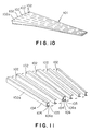
- Fig. 10 shows a second aircraft main wing 101, which does not form part of the present invention, in a perspective view.
- the aircraft main wing 101 has an intermediate spar 102a and a plurality of intermediate spars 102, each of which is made of a composite material and having a U-shaped cross section.
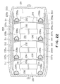
- the intermediate spars 102a and 102 are arranged in a manner that longitudinal flanges of adjacent intermediate spars 102a and 102 overlap and are in contact with each other. Overlapping portions of the longitudinal flanges of adjacent intermediate spars 102a and 102 are fastened together with fasteners 103 as show in Fig. 12 .
- the intermediate spars 102a and 102 are tapered toward their tips in shapes corresponding to those of divisions of the main wing 101 defined by splitting the main wing 101 spanwise.
- the intermediate spars 102a and 102 extend between a wing root and a wing tip of the main wing 101.
- the intermediate spars 102a and 102 are formed individually, for example, by a thermosetting composite material laminating method.
- each of the intermediate spars 102a and 102 is a member having a U-shaped cross section and having a web 104 serving as a vertical wall and flanges 105 and 106 formed integrally with the web 104.
- adjacent intermediate spars 102a and 102 are arranged in such a manner that flanges 105 and 106 of one of the intermediate spars 102a and 102 overlap portions of flanges 105 and 106 near a web 104 of the adjacent intermediate spar 104 and the overlapping portions of flanges 105 and 106 are fastened together to form the main wing 101 shown in Fig.
- the upper flanges 105 and the lower flanges 106 form sections of skins of the main wing 101. That is, outer surfaces of the upper flanges 105 of the intermediate flanges 102 and the lower flanges 106 of the same serve as sections of the surfaces of the main wing 101.
- the intermediate spar 102a disposed at one end of the arrangement of the intermediate spars 102 has joining parts 105a and 106a formed by recessing inner surfaces of edge portions of the flanges 105 and 106, respectively.
- the joining parts 105a and 106a of the intermediate spar 102a are formed by reducing the number of prepreg sheets laminated to form the intermediate spar 102a. Thicknesses of the joining parts 105a and 106a are smaller than that of other portions of the flanges 105 and 106 and are, for example, about half the thickness of the other portions of the flanges 105 and 106.
- the joining parts 105a and 106a are formed in the intermediate part 102a to join the intermediate spar 102a to the adjacent intermediate spar 102 in such a manner that the outer surfaces of the upper flanges 105 of the intermediate spars 102a and 102 are flush with each other and the outer surfaces of the lower flanges 106 of the same are flush with each other so as to conform to the sections of the outer surface of the main wing 101.
- stiffening members 107 made of a composite material, an aluminum alloy or a titanium alloy are arranged between the web 104 and the flanges 105 and 106 of the end intermediate spar 102a and are fastened to the web 104 and the flanges 105 and 106 by fasteners 103a, before joining the end intermediate spar 102a to the adjacent intermediate spar 102.
- the end intermediate spar 102a is capable of serving as the rear spar of the main wing 101.
- the intermediate spar 102 has a joining part 105a formed by recessing an inner surface of an edge portion and a joining part 105b formed by recessing an outer surface of a portion contiguous with the web 104 of the upper flange 105, respectively, and a joining part 106a formed by recessing an inner surface of an edge portion and a joining part 106b formed by recessing an outer surface of a portion contiguous with the web 104 of the lower flange 106, respectively.
- the joining parts 105a, 105b, 106a and 106b of the intermediate spar 102 are formed by reducing the number of prepreg sheets laminated to form the intermediate spar 102.
- Thicknesses of the joining parts 105a, 105b, 106a and 106b are smaller than that of other portions of the flanges 105 and 106 and are, for example, about half the thickness of the other portions of the flanges 105 and 106.
- the joining parts 105a, 105b, 106a and 106b are formed in the intermediate parts 102 to join the adjacent intermediate spar 102 together in such a manner that the outer surfaces of the upper flanges 105 of the intermediate spars 102 are flush with each other and the outer surfaces of the lower flanges 106 of the same are flush with each other so as to conform to sections of the outer surface of the main wing 101.
- stiffening members, and fixtures for holding a vent tube 108 or other fittings are fastened to the inner surface of the intermediate spar 102 with fasteners 103b or by secondary bonding means, before joining the intermediate spar 102 to the adjacent one.
- the intermediate spars 102 and 102a are formed by a thermosetting composite material laminating method or a thermosetting resin impregnation method, which are a generally known method and hence the description thereof will be omitted.
- the stiffening members 107 which have been made separately, are fastened to the web 104 and the flanges 105 and 106 of the end intermediate spar 102a by fasteners 103a.
- the fixtures for holding some fitting are also fastened to the end intermediate spar 102a.
- the stiffening members 107 or the like are easily fastened to the end intermediate spar 102a because the fastening operation can be set eyes on.
- the intermediate spars 102a and 102 are arranged in parallel to each other in such a manner that a portion of the intermediate spar 102 on the side of the joining parts 105b and 106b is pushed in the direction of the arrow A into a portion of the intermediate spar 102a on the side of the joining parts 105a and 106a. Consequently, the joining part 105a of the upper flange 105 of the intermediate spar 102a and the joining part 105b of the upper flange 105 of the intermediate spar 102 overlap each other and the joining part 106a of the lower flange 106 of the intermediate spar 102a and the joining part 106b of the lower flange 106 of the intermediate spar 102 overlap each other.
- the overlapping joining parts 105a and 105b and the overlapping joining parts 106a and 106b are fastened together with rivets 110 by an automatic riveting machine 109 shown in Fig. 13 . Since the respective upper flanges 105 of the intermediate spars 102a and 102 and the respective lower flanges 106 of the same form sections of the skins of the main wing 101, the outer surfaces of the upper flanges 105 of the intermediate spars 102a and 102 and the outer surfaces of the lower flanges 106 of the same form sections of a surface of the main wing 101 when the intermediate spars 102a and 102 are united together as shown in Fig. 10 .
- the thickness of the joining parts 105a, 105b, 106a and 106b is smaller than that of other portions of the flanges 105 and 106 and is, for example, half the thickness of the latter, the outer surfaces of the respective upper flanges 105 of the intermediate spars 102a and 102, and the outer surfaces of the respective lower flanges 106 of the intermediate spars 102a and 102 form sections of the gently curved surface of the main wing 101.
- the fixtures holding the vent tube 108, and stiffening members are fastened with the fasteners 103b to an inner surface of the web 104 of the intermediate spar 102 joined to the end intermediate spar 102a.
- the vent tube 108 can be easily attached to the web 104 of the intermediate spar 102 because the vent tube 108 is within sight during work for attaching the vent tube 108 to the intermediate spar 102.
- FIG. 15 Another intermediate spar 102 is arranged adjacent to the intermediate spar 102 provided with the vent tube 108 as shown in Fig. 15 . Then, a portion of the intermediate spar 102 on the side of the joining parts 105b and 106b is pushed into a portion of the intermediate spar 102a provided with the vent tube 108 on the side of the joining parts 105a and 106a. Consequently, the respective joining parts 105a and 105b of the upper flanges 105 of the intermediate spars 102 overlap each other and the respective joining parts 106a and 106b of the lower flanges 106 of the intermediate spars 102 overlap each other.
- the overlapping joining parts 105a and 105b and the overlapping joining parts 106a and 106b are fastened together with rivets 110 by the automatic riveting machine 109 shown in Fig. 13 . Since the respective upper flanges 105 of the intermediate spars 102 and the respective lower flanges 106 of the same form sections of the skins of the main wing 101, the outer surfaces of the upper flanges 105 of the intermediate spars 102 and the outer surfaces of the lower flanges 106 of the same form sections of the surface of the main wing 101 when the intermediate spars 102 are united together as shown in Fig. 10 .
- the plurality of intermediate spars 102 are joined together successively in the above manner, and a spar having a short flanges and a U- or I-shaped cross section is joined to the last intermediate spar 102 to complete the aircraft main wing 101.
- Intermediate spars having a cross section other than the U-shaped cross section may be used as well.
- intermediate spars 102b having an I-shaped cross section as shown in Fig. 16 may be used, and intermediate spars 102 having a U-shaped cross section and intermediate spars 102b having an I-shaped cross section may be used in combination as shown in Fig. 17 .
- an open space defined by intermediate spars 102 and 102b cannot be used for joining work to join together the intermediate spars 102 and 102b when an intermediate spar 102 having a U-shaped cross section and an intermediate spar 102b having an I-shaped cross section are used in combination
- the intermediate spars 102 and 102b can be joined together with blind fasteners, which are generally employed in assembling aircraft.
- the intermediate spar may be joined to the adjacent one after attaching the fittings or the like to the intermediate spar, provided that the fittings or the like are disposed in such a manner that the work for joining the intermediate spar to the adjacent one is not obstructed by the fittings or the like.
- the fasteners may be rivets or bolts.
- the main wing of composite material is formed by successively joining together the plurality of intermediate spars of composite material each having the upper and the lower flange and the web so that the upper and the lower flanges of the intermediate spars are arranged to form smooth surfaces conforming to the upper and the lower surfaces of the main wing. Therefore, the main wing has a great reduced number of parts and is capable of being assembled by greatly reduced manhours and of being fabricated at a low cost. Since spaces defined by the intermediate spars are easily accessible during assembling processes,the fittings can be easily disposed in the spaces and nondestructive testing can be easily achieved.
- the main wing of composite material is formed by joining together the overlapping portions (joining parts) with the fasteners after the portion of the intermediate spar on the side of the web thereof is arranged into the portion of the adjacent intermediate spar on the side opposite to the web thereof. Therefore, the main wing has a greatly reduced number of parts and is capable of being assembled by greatly reduced manhours and of being fabricated at a low cost. Since spaces defined by the intermediate spars are easily accessible during assembling processes, the fittings can be easily disposed in the spaces and nondestructive testing can be easily achieved.
- the wing 210 has an upper skin 212 provided with a plurality of stiffening parts 211 projecting from an inner surface thereof, a lower skin 214 provided with a plurality of stiffening parts 213 projecting from an inner surface thereof, and vertical flat plates 216.
- Each vertical flat plate 216 has upper and lower edge portions bonded to corresponding stiffening parts 211 and 213 of the skins 212 and 214 with adhesive films 215 of a thermosetting adhesive.
- the flat plates 216 functions as webs of channel-shaped spars.
- the skins 212 and 214 and the flat plates 216 before molding may be cured members of a fiber-reinforced composite material or half-cured members of a prepreg.
- the stiffening parts 211 and 213 of the skins 212 and 214 extend between a wing root and a wing tip of the wing 210 to bear principal load on the wing 210.
- the stiffening parts 211 and 213 have flat joining surfaces 217, so that the edge portions of the flat plates 216 can be firmly bonded to the stiffening parts 211 and 213.
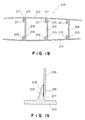
- Figs. 19 to 21 show joints of different types of the stiffening parts 211 and 213 and the flat plate 216; the joints are used selectively according to required strength. Since the joint of the upper edge portion and the stiffening part 211 of the upper skin 212 and the joint of the lower edge portion and the stiffening part 213 of the lower skin 214 are substantially the same, only the joint of the stiffening part 213 of the lower skin 214 and the lower edge portion of the flat plate 216 will be described and the description of the other joints will be omitted.
- the stiffening part 213 has a flat joining surface 217 to which the lower edge portion of the flat plate 216 is bonded and an inclined back surface 218.
- the inclined back surface 218 may be replaced with a stepped surface.
- the lower edge portion of the flat plate 216 is joined to the joining surface 217 of the stiffening part 213 with a thermosetting adhesive film 215.
- the stiffening part 213 has a flat joining surface 217 and an inclined joining surface 218 opposite the flat joining surface 217.
- a lower edge portion of the flat plate 216 is split into two joining portions 219 and 220.
- the joining portion 219 is bonded to the flat joining surface 217 with a thermosetting adhesive film 215 and the other joining portion 220 is bonded to the inclined joining surface 218 of the stiffening part 213 with a thermosetting adhesive film 215.
- the stiffening part 213 has a flat joining surface 217 and an inclined joining surface 218 opposite the flat joining surface 217.
- a lower edge portion of the flat plate 216 is bonded to the flat joining surface 217 with a thermosetting adhesive film 215.
- a thermosetting adhesive film 215 and a plurality of superposed prepreg sheets 221 are applied to an area from a lower end of the inclined joining surface 218 to a portion of the flat plate 216 extending upward from the upper end of the stiffening part 213. Heat and pressure are applied to the prepreg sheets 221 to bond the same to the inclined joining surface 218 and the portion of the flat plate 216.
- the number of the prepreg sheets 221 is dependent on a design of the wing.
- Fig. 22 shows an assembly of the skins 212 and 214 and the flat plates 216 shown in Fig. 19 placed in a split jig 230 in a state before forming.
- the split jig 230 can be split into an upper half jig 233 and a lower half jig 234.
- the upper half jig 233 has an inner surface of a shape conforming to an upper surface of the wing and the lower half jig 234 has an inner surface of a shape conforming to a lower surface of the wing.
- Forming jigs 232 are placed in closed spaces 231 defined by the skins 212 and 214 and the flat plates 216, respectively.
- Each forming jig 232 has a pair of pressing jigs 235a and 235b, and a stretchable jig 236 for moving the pressing jigs 235a and 235b away from each other.
- the pressing jig 235a has a pressure surface 237a for pressing the upper skin 212 against the inner surface of the upper half jig 233 and is provided with a silicone rubber bladder 238a on one side surface thereof.
- the silicone rubber bladder 238a is expanded by supplying a fluid at a pressure into the silicone rubber bladder 238a to press the upper edge portion of the flat plate 216 against the joining surface of the stiffening part 211 of the upper skin 212.
- the silicon rubber bladder 238a may be substituted by a silicone rubber solid which can expand to press the upper edge portion of the flat plate 216 against the joining surface of the stiffening part 211 of the upper skin 212 when it is heated.
- the pressing jig 235b has a pressure surface 237b for pressing the lower skin 214 against the inner surface of the lower half jig 234 and is provided with a silicone rubber bladder 238b on one side surface thereof.
- the silicone rubber bladder 238b is expanded by supplying a fluid at a pressure into the silicone rubber bladder 238b to press the lower edge portion of the flat plate 216 against the joining surface of the stiffening part 213 of the lower skin 214.
- the silicon rubber bladder 238a may be substituted by a silicone rubber solid which can expand when it is heated.
- the stretchable jig 236 is a split jig consisting of two longitudinal wedgelike parts respectively having slopes in sliding contact with each other. After clamping the upper half jig 233 and the lower half jig 234, the longitudinal wedgelike parts of the stretchable jig 236 are moved in opposite directions to move the pressing jigs 235a and 235b away from each other to press the upper skin 212 and the lower skin 214 against the upper half jig 233 and the lower half jig 234, respectively.
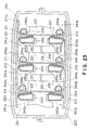
- Fig. 23 shows an assembly of the skins 212 and 214 and the flat plates 216 shown in Fig. 21 placed in another split jig 230 in a state before forming.
- the split jig 230 can be split into an upper half jig 233 and a lower half jig 234.
- Forming jigs 240 are placed in closed spaces 231 defined by the skins 212 and 214 and the flat plates 216, respectively.
- Each forming jig 240 has a pair of pressing jigs 241a and 241b, and a stretchable jig 242 for moving the pressing jigs 241a and 241b away from each other.
- the pressing jig 241a has a pressure surface 243a for pressing the upper skin 212 against the inner surface of the upper half jig 233 and is provided with silicone rubber bladders 244a and 245a on opposite side surfaces thereof, respectively.
- the silicone rubber bladder 244a is expanded by supplying a fluid at a pressure into the silicone rubber bladder 244a to press the upper edge portion of the flat plate 216 against the joining surface of the stiffening part 211 of the upper skin 212.
- the silicone rubber bladder 245a is expanded by supplying a fluid at a pressure into the silicone rubber bladder 245a to press the prepreg sheets 221 against the stiffening part 211 of the upper skin 212 and the flat plate 216.
- the pressing jig 241b has a pressure surface 243b for pressing the lower skin 214 against the inner surface of the lower half jig 234 and is provided with silicone rubber bladders 244b and 245b on opposite side surfaces thereof, respectively.
- the silicone rubber bladder 244b is expanded by supplying a fluid at a pressure into the silicone rubber bladder 244b to press the lower edge portion of the flat plate 216 against the joining surface of the stiffening part 213 of the lower skin 214.
- the silicone rubber bladder 245b is expanded by supplying a fluid at a pressure into the silicone rubber bladder 245b to press the prepreg sheets 221 against the stiffening part 213 of the lower skin 214 and the flat plate 216.
- the stretchable jig 242 is a split jig consisting of two longitudinal wedgelike parts respectively having slopes in sliding contact with each other. After clamping the upper half jig 233 and the lower half jig 234, the longitudinal wedgelike parts of the stretchable jig 242 are moved in opposite directions to move the pressing jigs 241a and 241b away from each other to press the upper skin 212 and the lower skin 214 against the upper half jig 233 and the lower half jig 234, respectively.
- the upper skin 212 provided with the stiffening parts 211 on the inner surface thereof, the lower skin 214 provided with the stiffening parts 213 on the inner surface thereof, and the flat plates 216 that can serve as webs of channel-shaped intermediate spars are individually made of a fiber-reinforced resin composite material.
- the upper skin 212 and the lower skin 214 are placed opposite to each other in the split jig.
- the flat plates 216 are arranged between the upper skin 212 and the lower skin 214 in such a manner that the upper edge portions thereof face the joining surfaces of the stiffening parts 211 of the upper skin 212 through the adhesive films 215, respectively, and that the lower edge portions thereof face the joining surfaces of the stiffening parts 213 of the lower skin 214 through the adhesive films 215, respectively.
- the upper and the lower end portions of the flat plates 216 are pressed against the joining surfaces of the stiffening parts 211 and 213 and heat is applied to the joining surfaces to bond the flat plates 216 to the stiffening parts 211 and 213 of the skins 212 and 214.
- the upper skin 212, the lower skin 214 and the flat plates 216 are united together.
- the upper skin 212 provided with the stiffening parts 211 on the inner surface thereof, the lower skin 214 provided with the stiffening parts 213 on the inner surface thereof, and the flat plates 216 serving as intermediate spars are individually made of a fiber-reinforced resin composite material.
- the upper skin 212, the lower skin 214 and the flat plates 216 may be either cured members or semicured members, respectively.
- the lower skin 214 is placed on the lower half jig 234.
- the lower half jig 234 has the inner surface of the shape corresponding to that of the lower surface of the wing.
- the flat plates 216 having opposite edge portions covered with the thermosetting adhesive films 215 are set on the lower skin 214 in such a manner that the lower edge portions face the joining surfaces of the stiffening parts 213 of the lower skin 214, respectively.
- the forming jigs 232 are placed in spaces between the adjacent flat plates 216, and the upper skin 212 is placed on the forming jigs 232 in such a manner that the stiffening parts 211 thereof face the upper edge portions of the flat plates 216, respectively.
- the forming jigs 232 may be placed on the lower skin 214 before setting the flat plates 216 on the lower skin 214.
- Positions of the forming jigs 232 are adjusted in such a manner that the respective outer surfaces of the skins 212 and 214 are shaped so as to conform accurately to the upper and the lower surface of the wing, respectively.
- the upper half jig 233 is placed on the upper skin 212.
- the upper half jig 233 has the inner surface of the shape corresponding to that of the upper surface of the wing.
- the upper half jig 233 and the lower half jig 234 are clamped together, the stretchable jigs 236 are operated to press the upper skin 212 against the upper half jig 233 by the pressing jigs 235a and to press the lower skin 214 against the lower half jig 234 by the pressing jigs 235b.
- the silicone rubber bladders 238a and 238b of the pressing jigs 235a and 235b are expanded by supplying the fluid at the pressure into the silicone rubber bladders 238a and 238b to press the upper and the lower edge portions of the flat plates 216 against the joining surfaces of the stiffening parts 211 of the upper skin 212 and the stiffening parts 213 of the lower skin 214, respectively.
- the skins 212 and 214 and the flat plates 216 are united in an assembly, and the assembly is subjected to a curing process or a thermocompression process to form the wing.
- the upper half jig 233 and the lower half jig 234 are separated from the wing, and then the forming jigs 232 are taken out of the wing through the wing root of the wing.
- Each of reinforcing members is a split member consisting of upper and a lower pieces.
- the upper and the lower pieces are passed through openings formed in the flat plates 216 and are fastened to appropriate portions of the wing with fasteners.
- the openings formed in the flat plates 216 and inspection holes formed in the skins 212 and 214 are used in attaching other component members to the wing.
- the assembly of the skins 212 and 214 and the flat plates 216 shown in Fig. 23 differs from that shown in Fig. 22 only in that the assembly shown in Fig. 23 is provided with the prepreg sheets 221 applied to the stiffening parts 211 of the upper skin 212 and the stiffening parts 213 of the lower skin 213. Therefore, the description of the steps of the method of forming the assembly shown in Fig. 23 that are the same as those of the method of forming the assembly shown in Fig. 22 will be omitted.
- the forming jigs 240 employed in forming the wing shown in Fig. 23 differ from the forming jigs 232 employed in forming the wing shown in Fig. 22 because the forming jigs 240 need to apply pressure to the prepreg sheets 221 applied to the stiffening parts 211 of the upper skin 212 and the stiffening parts 213 of the lower skin 214.
- Each forming jig 240 has the pressing jigs 241a and 241b.
- the pressing jig 241a is provided with the silicone rubber bladders 244a and 245a on opposite side surfaces thereof, respectively.
- the pressing jig 241b is provided with the silicone rubber bladders 244b and 245b on the opposite side surfaces thereof, respectively.
- the lower skin 214 is placed on the lower half jig 234 and the prepreg sheets 221 are applied to the inclined surfaces of the stiffening parts 213 of the lower skin 214.
- the forming jigs 240 are placed on the lower skin 214 and the upper skin 212 is placed on the forming jigs 240.
- the prepreg sheets 221 are attached beforehand to the inclined surfaces of the stiffening parts 211 of the upper skin 212.
- the upper half jig 233 and the lower half jig 234 are clamped together, and the upper skin 212 and the lower skin 214 are pressed against the upper half mold 233 and the lower half mold 234 by the pressing jigs 241a and 241b of the forming jigs 240. Then, the fluid is supplied at the pressure into the silicone rubber bladders 244a and 244b to expand the silicone rubber bladders 244a and 244b and to press the upper and the lower edge portions of the flat plates 216 against the flat joining surfaces of the stiffening parts 211 and 213 of the skins 212 and 214.
- the fluid is supplied at the pressure into the silicone rubber bladders 245a and 245b of the pressing jigs 241a and 241b to expand the silicone rubber bladders 245a and 245b and to press the prepreg sheets 221 against the inclined surfaces of the stiffening parts 211 and 213 of the skins 212 and 214 and against the upper and lower portions of the flat plates 216.
- the upper skin 212, the lower skin 214, the flat plates 216 and the prepreg sheets 221 are bonded together by a curing process to form the wing of composite material.
- the skins Since the upper and the lower skin of the wing are provided integrally with the stiffening parts that can bear principal load on the wing, the skins have a high rigidity, is easy to handle and has high dimensional stability.
- the wing of composite material according to the present invention has an appearance of improved quality and an external shape of improved accuracy because the outer surfaces of the upper and the lower skins are shaped by the surfaces of the jigs.
- the destructive testing of corners of the wing can be easily achieved because the wing has an open cross section.
- the upper and the lower skins are arranged so as to form a box structure of high accuracy, and then pressure is locally applied to the flat plates to join the flat plates to the stiffening parts so as to unite together the upper skin, the lower skin and the flat plates in an integral box structure. Therefore, joints of the upper and the lower skin and the flat plates are space from the corners and nondestructive testing can be easily achieved. Since partial jigs are used to form the box structure without using intermediate jigs that fill up internal spaces of the box structure, the cost for the jigs can be reduced.
- the method of forming the wing of composite material makes the component members individually and then assembles the component members. Therefore, the components members can be formed in a thickness effective in enhancing peel strength, and the wing can be formed in a strength-efficient structure having the sufficiently thick stiffening parts that bear the principal and the thin inner members.
Description
- The present invention relates to a wing of composite material for constructing an aircraft airframe and a method of fabricating the same.
- An aircraft wing of composite material is constructed by assembling a lower skin, an upper skin, spars and ribs by using assembling jigs and fastening together the lower skin, the upper skin, the spars and the ribs by using fastening means. Alternatively, an aircraft wing of composite material is constructed by forming a combined structure of composite material integrally including a lower skin (or an upper skin), spars and ribs and fastening an upper skin (or a lower skin) to the combined structure by using fastening means.
- The aircraft wing of composite material formed by fastening together the component members is a heavyweight structure comprising a large number of component parts. Since work for assembling the aircraft wing needs special assembling jigs, the aircraft wing is costly.
- The aircraft wing constructed by using the combined structure having either the lower skin or the upper skin is based on the conventional concept of structure, jigs and processes are complicated and hence the aircraft wing is costly.
- Reference is made to
EP-A-0257148 , in which a joint between a sandwich skin panel and an elongate structural frame element of an aircraft is formed using a woven fabric connector strap of substantially H-shaped cross-section formed by intersecting woven fabric webs in which each of the webs comprises a plurality of multifilament yarn strands extending side-by-side transversely to the longitudinal direction of the strap and passing directly through the intersecting web or webs, the crossing web having portions and projecting transversely from opposite sides of the two spaced upright webs of the connector. - Reference is also made to
EP-A-0217315 which discloses a wing box cover panel in which a plurality of channel-shaped members are positioned longitudinally along the inner surface of an outer skin, each member having a web and two flanges. Members are positioned laterally contiguously to each other so that, when the outer skin and the members are cured together, the webs form an inner skin portion and adjacent flanges form blade stiffeners. - The present invention has been made in view of the foregoing circumstances. Therefore, a first object of the present invention is to provide a wing of composite material having a greatly reduced number of component parts, and capable of being assembled by greatly reduced manhours and of being fabricated at a low cost, and a method of fabricating such a wing.
- Another object of the present invention to provide a wing of composite material having an improved appearance, and capable of being formed in dimensions of an improved accuracy, and a method of forming such a wing.
- There is disclosed herein, but not forming part of the present invention, a wing of composite material comprises: upper and lower skins, each of which has a root and a tip; and a plurality of intermediate spars arranged between the upper and the lower skins; wherein the plurality of intermediate spars extend from the roots to the tips of the upper and lowest skins, and are integrally formed with or adhesively bonded to the upper and the lower skins.
- The plurality of intermediate spars are provided with openings in their side walls, and reinforcing members are passed through the openings and are bonded to the upper and the lower skins and the intermediate spars.
- Two additional spars may extend from the roots to the tips, on opposite sides of the intermediate spars, and may be bonded to the upper and the lower skins.
- The wing of composite material is an aircraft main wing, and the intermediate spars extend from a wing root toward a wing tip.
- There is also disclosed herein, but not forming part of the present invention, a method of fabricating a wing of composite material comprising an upper skin, a lower skin and a plurality of intermediate spars arranged side by side so as to extend from roots toward tips of the upper and the lower skins, comprises the steps of: forming through holes in side walls of the plurality of intermediate spars; disposing the plurality of intermediate spars on one of the skins so that the through holes are aligned with each other; disposing the other skin on the plurality of intermediate spars; integrally forming the plurality of intermediate spars and the skins or adhesively bonding together the plurality of intermediate spars and the skins; and passing reinforcing members through the through holes of the plurality of intermediate spars and bonding the reinforcing members to the plurality of intermediate spars and the skins.
- The step of forming through holes in side walls of the plurality of intermediate spars includes the steps of: forming portions in which any prepreg sheets are not superposed in prepreg structures by intermittently superposing prepreg sheets on a hollow heat-resistant rubber bag; closing the portions in which any prepreg sheets are not superposed with closing members; curing the prepreg structures formed by superposing prepreg sheets; and removing the closing members from the prepreg structure after curing.
- Alternatively, the step of forming through holes in side walls of the plurality of intermediate spars includes the steps of: winding rovings around a laminating jig to form a roving structure; cutting out portions of the roving structure formed on the laminating jig to form openings; closing the openings with closing members; impregnating the roving structure with a resin and curing the resin-impregnated roving structure; and removing the closing members from the resin-impregnated roving structure after curing.
- There is further disclosed herein, but not forming part of the present invention, a wing of composite material comprises a plurality of intermediate spars of composite material each having upper and lower flanges forming sections of upper and lower skins, and a web formed integrally with and extending between the upper and lower flange; wherein the plurality of intermediate spars are united together so that surfaces of the upper and lower flanges form surfaces of the upper and the lower skin, respectively.
- Each intermediate spar having the upper and the lower flanges and the web has a U-shaped cross section, adjacent intermediate spars are united together in such a manner that outer surfaces of portions of the flanges contiguous with an outer surface of the web of one of the intermediate spars are in contact with inner surfaces of edge portions of the flanges of the other intermediate spar, and the portions of the adjacent intermediate spars in contact with each other are fastened together with fasteners.
- The wing is an aircraft main wing, and the intermediate spars extend from a wing root toward a wing tip.
- According to an aspect of the present invention, there is provided a wing of composite material comprising:
- upper and lower skins of composite material provided with stiffening parts on inner surfaces thereof, respectively; and
- flat plates extended between and united to the upper and lower skin by adhesively bonding opposite edge portions thereof to the stiffening parts;
- Preferably, the flat plates extended between a wing root and a wing tip.
- Preferably, the number of the flat plates is at least three, and the flat plates are disposed in a parallel arrangement.
- There is also disclosed herein, but not forming part of the present invention, a method of fabricating a wing of composite material, comprises the steps of: forming upper and lower skins of a fiber-reinforced resin composite material having stiffening parts on inner surfaces thereof, respectively; placing the upper and the lower skin at an interval in a die; disposing flat plates between the upper and the lower skin in such a manner that upper and lower edge portions thereof face the stiffening parts, respectively; and uniting together the upper and the lower skin by adhesively bonding the upper and the lower edge portions of the flat plates to the stiffening parts.
- According to a further aspect of the present invention, a method of fabricating a wing of composite material comprises the steps of:
- forming an upper skin, a lower skin and flat plates of a fiber-reinforced resin composite material, the skins having stiffening parts on inner surfaces thereof, respectively, each of the stiffening parts having a flat joining surface and an inclined surface opposite the flat joining surface;
- placing the lower skin on a lower half die;
- applying a lower prepreg sheet to the inclined surface of the stiffening parts of the lower skin;
- disposing the flat plates in such a manner that lower edge portions thereof face the flat joining surface of the stiffening parts of the lower skin;
- disposing a forming jig on the lower skin, the forming jig having pressing jigs, first stretchable jigs for pressing the flat plates against the flat joining surfaces of the skins and second stretchable jigs for pressing the lower prepreg sheet against the inclined surfaces on the stiffening parts;
- placing the upper skin with an upper prepreg sheet on the forming jig in such a manner that the stiffening parts thereof face upper edge portions of the flat plates;
- placing an upper half die on the upper skin;
- clamping together the upper and lower half die;
- moving and pressing the upper skin against an inner surface of the upper half die by the pressing jig;
- pressing the upper and the lower edge portions of the flat plates against the flat joining surfaces of the stiffening parts by the first stretchable jigs and pressing the upper and the lower prepreg sheets against the inclined surfaces of the stiffening parts by the second stretchable jigs;
- and bonding the upper skin, the lower skin, the flat plates and the upper prepreg sheets together by a curing process.
- By way of example only, specific embodiments of the present invention will now be described, with reference to the accompanying drawings, in which:-
-
-
Fig. 1 is an exploded perspective view of a first aircraft main wing of composite material, which does not form part of the present invention; -
Fig. 2 is an enlarge sectional view of the main wing shown inFig. 1 ; -
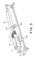
Fig. 3 is a perspective view of a laminating device for fabricating an intermediate spar of a wing of composite material; -
Fig. 4 is a sectional view of a device for fabricating a wing of composite material; -
Fig. 5 is a sectional view taken on line A-A ofFig. 4 ; -
Fig. 6 is a perspective a view of another laminating device for fabricating an intermediate spar of a wing of composite material; -
Fig. 7 is a view of another device for fabricating a wing of composite material; -
Fig. 8 is a sectional view of a third device for fabricating a wing of composite material; -
Fig. 9 is an enlarged view of a portion A ofFig. 8 ; -
Fig. 10 is a perspective view of a second aircraft main wing of composite material, which does not form part of the present invention; -
Fig. 11 is an exploded perspective view of the main wing shown inFig. 10 ; -
Fig. 12 is view of joining intermediate spars of a wing of composite material; -
Fig. 13 is a view of a joining device for joining together the intermediate spars of a wing of composite material; -
Fig. 14 is a view of intermediate spars of a wing of composite material in a phase before a joining process; -
Fig. 15 is a view of intermediate spars of a wing of composite material in a phase after a joining process; -
Fig. 16 is a view of joined intermediate spars having an I-shaped cross section;. -
Fig. 17 is a view of an intermediate spar having an I-shaped cross section and an intermediate spar having a U-shaped cross section joined together; -
Fig. 18 is a schematic, fragmentary sectional view of a third wing of composite material, which does not form part of the present invention; -
Fig. 19 is a view of a joining part of a skin and a flat plate of a wing of composite material, which does not form part of the present invention; -
Fig. 20 is a view of another joining part of a skin and a flat plate of a wing of composite material, in accordance with the present invention; -
Fig. 21 is a view of a third joining part of a skin and a flat plate of a wing of composite material, in accordance with the present invention; -
Fig. 22 is a schematic view of a jig for locally applying a bonding pressure to be used in carrying out a method of forming a wing of composite material, in accordance with the present invention; and -
Fig. 23 is a schematic view of another jig for locally applying a bonding pressure to be used in carrying out a method of forming a wing of composite material, in accordance with the present invention. - Preferred embodiments of the present invention will be described hereinafter with reference to the accompanying drawings.
-
Fig. 1 is an exploded perspective view of a first aircraft main wing of composite material, which does not form part of the present invention. An aircraft main wing 1 has anupper skin 2, alower skin 3 and a plurality ofintermediate spars 4 disposed between theupper skin 2 and thelower skin 3. Theupper skin 2, thelower skin 3 and theintermediate spars 4 are made of a fiber-reinforced resin composite material. Theupper skin 2, thelower skin 3 and theintermediate spars 4 are united together in an integral box structure by a thermocompression process. - In the aircraft main wing 1 shown in
Fig. 1 , the fiveintermediate spars 4 are arranged contiguously with respect to a front-rear direction (a direction perpendicular to a span of the aircraft main wing 1) so as to extend from a wing root toward a wing tip. Some of the five intermediate spars 5 terminate at the wing tip. When theintermediate spars 4 are tapered toward the wing tip, theintermediate spares 4 can be arranged side by side so that all theintermediate spars 4 extend from the wing root to the wing tip. - A front edge and a rear edge of the integral box structure are trimmed. A front spar 5 is fastened to the front edge with ordinary fasteners, and a rear spar 6 is fastened to the rear edge with ordinary fasteners.
- A plurality of stiffening
ribs 7 are disposed at predetermined longitudinal positions on the main wing 1. Eachrib 7 is formed of an upper member 7a and alower members 7b. As shown inFig. 2 , eachrib 7 is joined to theupper skin 2, thelower skin 3 and theintermediate spars 4 to provide the main wing 1 with structural strength and ridgidity. In this arrangement, eachrib 7 is split into the upper and the lower members, and the upper and the lower members are formed by molding and are - inserted in the main wing 1 through openings formed in the
intermediate spars 4. A method of fabricating the wing of composite material will be explained. - A first, a method of laminating thermosetting composite material with prepreg will be explained.
- A hollow bag (bladder) 11 made of silicone rubber, which has a length longer than that of an
intermediate spar 4 and a wall thickness of about 3 mm, is put on a core 10 shown inFig. 3 . A release agent is applied to thehollow bag 11. Prepreg sheets including resin are superposed on thehollow bag 11 put on thecore 10 by a fiber-placement automatic laminating machine, so as to form alaminated prepreg structure 12 having in side walls thereofgrooves 13 andopenings 14 for passing ribs therethrough. The fiber-placement automatic laminating machine controls a laminating angle of the prepreg sheets regardless of variation of spanwise section. Portions Portions of the prepreg sheets corresponding to thegroves 13 and theopenings 14 may be, for example, cut out. After thelaminated prepreg structure 12 has been formed, thecore 10 is removed therefrom, and thegrooves 13 theopenings 14 are closed by closingplugs laminated prepreg structure 12 for the intermediate spar is completed. - As shown in
Fig. 4 ,prepreg sheets 21 for forming a lower skin are laminated on a lower formingdie 22. A plurality ofhollow bags 11 holding theprepreg structures 12 thereon are arranged on thelaminated prepreg sheets 21 and upperskin prepreg sheets 25 are laminated on the plurality ofprepreg structures 12 to form an assembly. Side blocks 23 having upper and lower surfaces of shapes conforming to those of the upper and the lower skins, and fairing bars 24 for holding edge portions of the wing assembly in correct shapes are applied to the assembly. Acowl plate 26 having a lower surface of a shape conforming to a wing surface is placed on the laminated upperskin prepreg sheets 25. - Then, the laminated lower
skin prepreg sheets 21, theprepreg structures 12 forming the intermediate spars and covering thehollow bags 11, the laminated upperskin prepreg sheets 25, thecowl plate 26 and the fairing bars 24 are covered with avacuum bag 27 opening into ends of inside hollows of thehollow bags 11 as shown inFig. 5 . Gaps between the lower formingdie 22 and thehollow bags 11 are sealed withsealant strips - A space covered with the
vacuum bag 27 is evacuated and heat and pressure are applied to the laminated lowerskin prepreg sheets 21, theprepreg structures 12 and the laminated upperskin prepreg sheets 25. Thus, the laminated lowerskin prepreg sheets 21, theprepreg structures 12 forming the intermediate spars and the laminated upperskin prepreg sheets 25, are formed into an integral box structure, i.e., a principal part of the wing of composite material. - The fairing bars 24 are removed from the lower forming
die 22, the side blocks 23 and thehollow bags 11 are removed from the integral box structure, and the closing plugs 13a and 14a are removed from thegrooves 13 and theopenings 14 of theintermediate spars 4. - Then, the
ribs 7 each capable of being split into the upper member 7a and thelower member 7b are inserted from one side of the integral box structure through thegrooves 13 and theopenings 14 of theintermediate spars 4 to the other side of the integral box structure. Theribs 7 are joined to theupper skin 2, thelower skin 3 and theintermediate spars 4 by the ordinary fasteners. - The front edge and the rear edge of the integral box structure provided with the
ribs 7 are trimmed. The front spar 5 and the rear spar 6 are attached to the front edge and the rear edge, respectively, of the trimmed integral box structure by ordinary fasteners to complete the wing of composite material. - Since the above method of fabricating the wing of composite material connects the ribs to the integral box structure by the fasteners (fastening means), it needs much less time, the box structure can be formed in a lightweight structure, and the number of parts can be reduced, which enables the wing to be fabricated at a reduced cost.
- A method of forming an integral box structure using a thermosetting resin impregnation process will be described with reference to
Figs. 6 and7 . - Referring to
Fig. 6 ,rovings 12a of many filaments are wound in a roving structure round a laminating jig 10a of an iron alloy or a CFRP. Portions of the roving structure are cut out to formgrooves 13 andopenings 14 for passing ribs therethrough. Thegrooves 13 and theopenings 14 are closed by silicone rubber plates or aluminum alloy plates. The laminating jig 10a is divided longitudinally obliquely into parts to facilitate removing the same from a molded structure formed thereon. - As shown in
Fig. 7 ,fabrics 34 for stiffening a lower skin is superposed on alower mold 31. A plurality of laminating jigs 10a each holding the roving structure formed by winding therovings 12a thereon are arranged side by side on the superposedfabrics 34.Fabrics 35 for stiffening an upper skin are superposed on the roving structures held on the laminating jigs 10a, and anupper mold 32 is placed on thefabrics 35. Theupper mold 32 and thelower mold 31 are clamped by aclamping device 33 so as to form a sealed space therein. Apipe 36 provided with avalve 37 is connected to thelower mold 31 so as to communicate with the sealed space. Apipe 38 provided with avalve 39 is connected to theupper mold 32 so as to communicate with the sealed space. - The sealed space defined by the
upper mold 32 and thelower mold 31 is evacuated through thepipe 38 connected to theupper mold 32, and a thermosetting resin is injected into the sealed space through thepipe 36 connected to thelower mold 31. The sealed space is evacuated through thepipe 38 connected to theupper mold 32 until the thermosetting resin injected through thepipe 36 connected to thelower mold 31 into the sealed space overflows the mold through thepipe 38 connected to theupper mold 32. Once the thermosetting resin is sucked into thepipe 38 connected to theupper mold 32, thevalve 39 on thepipe 38 is closed and the thermosetting resin is forced and pressed into the sealed space through thepipe 36 connected to thelower mold 31. - Then, heat and pressure is applied to the thermosetting resin injected into the mold to complete an integral box structure, i.e., a principal part of a wing of composite material.
- The
upper mold 32, thelower mold 31 and the laminating jig 10a are separated from the integral box structure and the silicone rubber plate or aluminum alloy plate are removed. Subsequently,ribs 7 each capable of being split into an upper member 7a and alower member 7b are inserted from one side of the integral box structure through thegrooves 13 and theopenings 14 ofintermediate spars 4 to the other side of the integral box structure. Theribs 7 are joined to anupper skin 2, alower skin 3 and theintermediate spars 4 by the ordinary fasteners. - The front edge and the rear edge of the integral box structure provided with the
ribs 7 are trimmed. The front spar and the rear spar are attached to the front edge and the rear edge, respectively, of the trimmed integral box structure by ordinary fasteners to complete a wing of composite material. - A molding method of fabricating a wing of composite material employing a co-bond molding method adhesively bonds together a cured member of a composite material and an uncured member of a composite material. In this molding method, two skins are formed beforehand, for example, by a thermosetting composite material laminating process or by a thermosetting resin impregnation process. As mentioned in the description of the method of fabricating a wing employing a thermosetting composite material laminating process, intermediate spars are formed by laminating prepreg sheets on hollow bags, and the intermediate spars are placed via an adhesive on a skin placed on a lower forming die. The other skin is bonded to the intermediate spars with an adhesive to form an assembly. Heat and pressure are applied to the assembly for curing by a method similar to the previously described method of fabricating a wing employing the thermosetting composite material laminating method.
- As shown in
Fig. 8 , theupper skin 2 and thelower skin 3 may be provided withribs 40 at positions corresponding to vertical walls, which are formed between the contiguously arrangedintermediate spars 4 and extending between theupper skin 2 and thelower skin 3. The skin provided with theribs 40 is formed by laminating a plurality of prepreg sheets (each of which has a groove at an end thereof) on a plurality of segments of a lower split die having an upper surface of a shape conforming to that of a lower surface of the wing, joining the segments together, laminating additional prepreg sheets on the laminated prepreg sheets, placing an upper die having a lower surface of a shape conforming to that of an upper surface of the wing on the laminated prepreg sheets, and applying heat and pressure to the laminated prepreg sheets. - The
laminated prepreg structure 12 formed on thehollow bag 11 is split properly, for example, split into half-circular divisions and the half-circular divisions are arranged so that edge portions thereof do not overlap each other or are not in contact with each other. Thelaminated prepreg structure 12 thus formed is expanded by thehollow bag 11 that expands when a pressure is applied thereto during a molding process. Thus,laminated prepreg structure 12 can be firmly pressed against and bonded to theskins intermediate spars 4 can be firmly pressed against and bonded to each other. - The molded
skins ribs 40 can be individually subjected to a nondestructive test. Thus, nondestructive testing of portions of the wing in the vicinity of the surfaces of the wing, which must be strong, can be facilitated. Since the ribs combined with theskins skins skins skins skins - The wing of composite material as described can be fabricated by a method wherein plural component members of the wing are formed individually and they are adhesively bonded together. This method is called a secondary bonding method, wherein the skins and the intermediate spars are individually formed and adhesively bonded together.
- After the skins and the intermediate spars are formed individually by the thermosetting composite material laminating method or the thermosetting resin impregnation method, the skins and the intermediate spars may be removed from the molds and may be subjected to a shaping process. When the wing is fabricated by this method, the grooves and the openings can be formed in the intermediate spars after curing.
- When uniting together the individually formed skins and the intermediate spars, one of the skins is placed on a lower forming die, the intermediate spars are arranged on the skin, and the other skin is placed on the intermediate spars. An adhesive is applied to the joining parts of those component members, and heat and pressure are applied to the joining parts.
- The foregoing wing of composite material has the upper skin, the lower skin, the plurality of intermediate spars arranged between the upper and the lower skin. The intermediate spars are extended between the roots and the tips of the upper and the lower skins, and the intermediate spars are formed integrally with the upper and the lower skins or are adhesively bonded to the upper and the lower skins. Thus, the wing needs a relatively small number of component parts and a greatly reduced fabricating time and can be fabricated at a low cost.
- The foregoing method of fabricating the wing of composite material having the upper skin, the lower skin, and the plurality of intermediate spars arranged side by side between the upper and the lower skins and extended from the wing root toward the wing tip: forms through holes in the intermediate spars substantially perpendicularly to a longitudinal direction of the intermediate spars, arranges the plurality of intermediate spars on one of the skins with the through holes thereof aligned with each other, places the other skin on the plurality of intermediate spars, adhesively bonds together the intermediate spars and the skins, passes the stiffening ribs through the through holes of the intermediate spars, and connects the stiffening ribs to the intermediate spars and the skins. Thus, the number of parts can be greatly reduced, the stiffening ribs can be easily arranged, the wing of composite material has sufficient structural strength and rigidity and the fabrication of the wing requires greatly reduced manhours.
- A second wing of composite material, which does not form part of the present invention, will be described hereinafter.
-
Fig. 10 shows a second aircraftmain wing 101, which does not form part of the present invention, in a perspective view. The aircraftmain wing 101 has anintermediate spar 102a and a plurality ofintermediate spars 102, each of which is made of a composite material and having a U-shaped cross section. Theintermediate spars intermediate spars intermediate spars fasteners 103 as show inFig. 12 . - As shown in
Fig. 11 , theintermediate spars main wing 101 defined by splitting themain wing 101 spanwise. Theintermediate spars main wing 101. Theintermediate spars - As shown in
Figs. 11 and12 , each of theintermediate spars web 104 serving as a vertical wall andflanges web 104. When adjacentintermediate spars intermediate spars flanges web 104 of the adjacentintermediate spar 104 and the overlapping portions offlanges main wing 101 shown inFig. 10 , theupper flanges 105 and thelower flanges 106 form sections of skins of themain wing 101. That is, outer surfaces of theupper flanges 105 of theintermediate flanges 102 and thelower flanges 106 of the same serve as sections of the surfaces of themain wing 101. - As shown in
Fig. 14 , theintermediate spar 102a disposed at one end of the arrangement of theintermediate spars 102 has joiningparts flanges parts intermediate spar 102a are formed by reducing the number of prepreg sheets laminated to form theintermediate spar 102a. Thicknesses of the joiningparts flanges flanges parts intermediate part 102a to join theintermediate spar 102a to the adjacentintermediate spar 102 in such a manner that the outer surfaces of theupper flanges 105 of theintermediate spars lower flanges 106 of the same are flush with each other so as to conform to the sections of the outer surface of themain wing 101. - As shown in
Fig. 14 , stiffeningmembers 107 made of a composite material, an aluminum alloy or a titanium alloy are arranged between theweb 104 and theflanges intermediate spar 102a and are fastened to theweb 104 and theflanges fasteners 103a, before joining the endintermediate spar 102a to the adjacentintermediate spar 102. The endintermediate spar 102a is capable of serving as the rear spar of themain wing 101. - As shown in
Fig. 14 , theintermediate spar 102 has a joiningpart 105a formed by recessing an inner surface of an edge portion and a joiningpart 105b formed by recessing an outer surface of a portion contiguous with theweb 104 of theupper flange 105, respectively, and a joiningpart 106a formed by recessing an inner surface of an edge portion and a joiningpart 106b formed by recessing an outer surface of a portion contiguous with theweb 104 of thelower flange 106, respectively. The joiningparts intermediate spar 102 are formed by reducing the number of prepreg sheets laminated to form theintermediate spar 102. Thicknesses of the joiningparts flanges flanges parts intermediate parts 102 to join the adjacentintermediate spar 102 together in such a manner that the outer surfaces of theupper flanges 105 of theintermediate spars 102 are flush with each other and the outer surfaces of thelower flanges 106 of the same are flush with each other so as to conform to sections of the outer surface of themain wing 101. - As shown in
Fig. 15 , stiffening members, and fixtures for holding avent tube 108 or other fittings are fastened to the inner surface of theintermediate spar 102 withfasteners 103b or by secondary bonding means, before joining theintermediate spar 102 to the adjacent one. - The
intermediate spars - A method of fabricating the aircraft
main wing 101 provided with theintermediate spars - As shown in
Fig. 14 , the stiffeningmembers 107, which have been made separately, are fastened to theweb 104 and theflanges intermediate spar 102a byfasteners 103a. The fixtures for holding some fitting are also fastened to the endintermediate spar 102a. The stiffeningmembers 107 or the like are easily fastened to the endintermediate spar 102a because the fastening operation can be set eyes on. - As shown in
Fig. 14 , theintermediate spars intermediate spar 102 on the side of the joiningparts intermediate spar 102a on the side of the joiningparts part 105a of theupper flange 105 of theintermediate spar 102a and the joiningpart 105b of theupper flange 105 of theintermediate spar 102 overlap each other and the joiningpart 106a of thelower flange 106 of theintermediate spar 102a and the joiningpart 106b of thelower flange 106 of theintermediate spar 102 overlap each other. - The
overlapping joining parts overlapping joining parts rivets 110 by an automaticriveting machine 109 shown inFig. 13 . Since the respectiveupper flanges 105 of theintermediate spars lower flanges 106 of the same form sections of the skins of themain wing 101, the outer surfaces of theupper flanges 105 of theintermediate spars lower flanges 106 of the same form sections of a surface of themain wing 101 when theintermediate spars Fig. 10 . Since the thickness of the joiningparts flanges upper flanges 105 of theintermediate spars lower flanges 106 of theintermediate spars main wing 101. - As shown in
Fig. 15 , the fixtures holding thevent tube 108, and stiffening members are fastened with thefasteners 103b to an inner surface of theweb 104 of theintermediate spar 102 joined to the endintermediate spar 102a. Thevent tube 108 can be easily attached to theweb 104 of theintermediate spar 102 because thevent tube 108 is within sight during work for attaching thevent tube 108 to theintermediate spar 102. - Then, another
intermediate spar 102 is arranged adjacent to theintermediate spar 102 provided with thevent tube 108 as shown inFig. 15 . Then, a portion of theintermediate spar 102 on the side of the joiningparts intermediate spar 102a provided with thevent tube 108 on the side of the joiningparts parts upper flanges 105 of theintermediate spars 102 overlap each other and the respective joiningparts lower flanges 106 of theintermediate spars 102 overlap each other. - The
overlapping joining parts overlapping joining parts rivets 110 by the automaticriveting machine 109 shown inFig. 13 . Since the respectiveupper flanges 105 of theintermediate spars 102 and the respectivelower flanges 106 of the same form sections of the skins of themain wing 101, the outer surfaces of theupper flanges 105 of theintermediate spars 102 and the outer surfaces of thelower flanges 106 of the same form sections of the surface of themain wing 101 when theintermediate spars 102 are united together as shown inFig. 10 . - The plurality of
intermediate spars 102 are joined together successively in the above manner, and a spar having a short flanges and a U- or I-shaped cross section is joined to the lastintermediate spar 102 to complete the aircraftmain wing 101. - Intermediate spars having a cross section other than the U-shaped cross section may be used as well. For example,
intermediate spars 102b having an I-shaped cross section as shown inFig. 16 may be used, andintermediate spars 102 having a U-shaped cross section andintermediate spars 102b having an I-shaped cross section may be used in combination as shown inFig. 17 . Although an open space defined byintermediate spars intermediate spars intermediate spar 102 having a U-shaped cross section and anintermediate spar 102b having an I-shaped cross section are used in combination, theintermediate spars - Although the stiffening members, the fixtures or the fittings are attached to the intermediate spar after joining the intermediate spar to the adjacent one in fabricating the main wing in this arrangement in order to avoid obstructing work for joining the intermediate spar to the adjacent one, the intermediate spar may be joined to the adjacent one after attaching the fittings or the like to the intermediate spar, provided that the fittings or the like are disposed in such a manner that the work for joining the intermediate spar to the adjacent one is not obstructed by the fittings or the like.
- The fasteners may be rivets or bolts.
- Thus, the main wing of composite material is formed by successively joining together the plurality of intermediate spars of composite material each having the upper and the lower flange and the web so that the upper and the lower flanges of the intermediate spars are arranged to form smooth surfaces conforming to the upper and the lower surfaces of the main wing. Therefore, the main wing has a great reduced number of parts and is capable of being assembled by greatly reduced manhours and of being fabricated at a low cost. Since spaces defined by the intermediate spars are easily accessible during assembling processes,the fittings can be easily disposed in the spaces and nondestructive testing can be easily achieved.
- In addition, the main wing of composite material is formed by joining together the overlapping portions (joining parts) with the fasteners after the portion of the intermediate spar on the side of the web thereof is arranged into the portion of the adjacent intermediate spar on the side opposite to the web thereof. Therefore, the main wing has a greatly reduced number of parts and is capable of being assembled by greatly reduced manhours and of being fabricated at a low cost. Since spaces defined by the intermediate spars are easily accessible during assembling processes, the fittings can be easily disposed in the spaces and nondestructive testing can be easily achieved.
- A third wing of composite material, which does not form part of the present invention, will be described hereinafter. Referring to
Fig. 18 showing thewing 210 of composite material of the third wing in a schematic, fragmentary sectional view, thewing 210 has anupper skin 212 provided with a plurality of stiffeningparts 211 projecting from an inner surface thereof, alower skin 214 provided with a plurality of stiffeningparts 213 projecting from an inner surface thereof, and verticalflat plates 216. Each verticalflat plate 216 has upper and lower edge portions bonded to correspondingstiffening parts skins adhesive films 215 of a thermosetting adhesive. Theflat plates 216 functions as webs of channel-shaped spars. Theskins flat plates 216 before molding may be cured members of a fiber-reinforced composite material or half-cured members of a prepreg. - The stiffening
parts skins wing 210 to bear principal load on thewing 210. The stiffeningparts surfaces 217, so that the edge portions of theflat plates 216 can be firmly bonded to the stiffeningparts -
Figs. 19 to 21 show joints of different types of the stiffeningparts flat plate 216; the joints are used selectively according to required strength. Since the joint of the upper edge portion and thestiffening part 211 of theupper skin 212 and the joint of the lower edge portion and thestiffening part 213 of thelower skin 214 are substantially the same, only the joint of thestiffening part 213 of thelower skin 214 and the lower edge portion of theflat plate 216 will be described and the description of the other joints will be omitted. - In the joint of the
stiffening part 213 and theflat plate 216 shown inFig. 19 , the stiffeningpart 213 has a flat joiningsurface 217 to which the lower edge portion of theflat plate 216 is bonded and aninclined back surface 218. Theinclined back surface 218 may be replaced with a stepped surface. The lower edge portion of theflat plate 216 is joined to the joiningsurface 217 of thestiffening part 213 with a thermosettingadhesive film 215. - In the joint of the
stiffening part 213 and theflat plate 216 shown inFig. 20 , the stiffeningpart 213 has a flat joiningsurface 217 and an inclined joiningsurface 218 opposite the flat joiningsurface 217. A lower edge portion of theflat plate 216 is split into two joiningportions portion 219 is bonded to the flat joiningsurface 217 with a thermosettingadhesive film 215 and the other joiningportion 220 is bonded to the inclined joiningsurface 218 of thestiffening part 213 with a thermosettingadhesive film 215. - In the joint of the
stiffening part 213 and theflat plate 216 shown inFig. 21 , the stiffeningpart 213 has a flat joiningsurface 217 and an inclined joiningsurface 218 opposite the flat joiningsurface 217. A lower edge portion of theflat plate 216 is bonded to the flat joiningsurface 217 with a thermosettingadhesive film 215. A thermosettingadhesive film 215 and a plurality ofsuperposed prepreg sheets 221 are applied to an area from a lower end of the inclined joiningsurface 218 to a portion of theflat plate 216 extending upward from the upper end of thestiffening part 213. Heat and pressure are applied to theprepreg sheets 221 to bond the same to the inclined joiningsurface 218 and the portion of theflat plate 216. The number of theprepreg sheets 221 is dependent on a design of the wing. -
Fig. 22 shows an assembly of theskins flat plates 216 shown inFig. 19 placed in asplit jig 230 in a state before forming. Thesplit jig 230 can be split into anupper half jig 233 and alower half jig 234. Theupper half jig 233 has an inner surface of a shape conforming to an upper surface of the wing and thelower half jig 234 has an inner surface of a shape conforming to a lower surface of the wing. Formingjigs 232 are placed inclosed spaces 231 defined by theskins flat plates 216, respectively. Each formingjig 232 has a pair of pressingjigs stretchable jig 236 for moving thepressing jigs - The
pressing jig 235a has apressure surface 237a for pressing theupper skin 212 against the inner surface of theupper half jig 233 and is provided with asilicone rubber bladder 238a on one side surface thereof. Thesilicone rubber bladder 238a is expanded by supplying a fluid at a pressure into thesilicone rubber bladder 238a to press the upper edge portion of theflat plate 216 against the joining surface of thestiffening part 211 of theupper skin 212. Thesilicon rubber bladder 238a may be substituted by a silicone rubber solid which can expand to press the upper edge portion of theflat plate 216 against the joining surface of thestiffening part 211 of theupper skin 212 when it is heated. - The
pressing jig 235b has apressure surface 237b for pressing thelower skin 214 against the inner surface of thelower half jig 234 and is provided with asilicone rubber bladder 238b on one side surface thereof. Thesilicone rubber bladder 238b is expanded by supplying a fluid at a pressure into thesilicone rubber bladder 238b to press the lower edge portion of theflat plate 216 against the joining surface of thestiffening part 213 of thelower skin 214. Thesilicon rubber bladder 238a may be substituted by a silicone rubber solid which can expand when it is heated. - The
stretchable jig 236 is a split jig consisting of two longitudinal wedgelike parts respectively having slopes in sliding contact with each other. After clamping theupper half jig 233 and thelower half jig 234, the longitudinal wedgelike parts of thestretchable jig 236 are moved in opposite directions to move thepressing jigs upper skin 212 and thelower skin 214 against theupper half jig 233 and thelower half jig 234, respectively. -
Fig. 23 shows an assembly of theskins flat plates 216 shown inFig. 21 placed in anothersplit jig 230 in a state before forming. Thesplit jig 230 can be split into anupper half jig 233 and alower half jig 234. Formingjigs 240 are placed inclosed spaces 231 defined by theskins flat plates 216, respectively. Each formingjig 240 has a pair of pressingjigs 241a and 241b, and astretchable jig 242 for moving thepressing jigs 241a and 241b away from each other. - The
pressing jig 241a has apressure surface 243a for pressing theupper skin 212 against the inner surface of theupper half jig 233 and is provided withsilicone rubber bladders silicone rubber bladder 244a is expanded by supplying a fluid at a pressure into thesilicone rubber bladder 244a to press the upper edge portion of theflat plate 216 against the joining surface of thestiffening part 211 of theupper skin 212. Thesilicone rubber bladder 245a is expanded by supplying a fluid at a pressure into thesilicone rubber bladder 245a to press theprepreg sheets 221 against the stiffeningpart 211 of theupper skin 212 and theflat plate 216. - The pressing jig 241b has a
pressure surface 243b for pressing thelower skin 214 against the inner surface of thelower half jig 234 and is provided withsilicone rubber bladders silicone rubber bladder 244b is expanded by supplying a fluid at a pressure into thesilicone rubber bladder 244b to press the lower edge portion of theflat plate 216 against the joining surface of thestiffening part 213 of thelower skin 214. Thesilicone rubber bladder 245b is expanded by supplying a fluid at a pressure into thesilicone rubber bladder 245b to press theprepreg sheets 221 against the stiffeningpart 213 of thelower skin 214 and theflat plate 216. - The
stretchable jig 242 is a split jig consisting of two longitudinal wedgelike parts respectively having slopes in sliding contact with each other. After clamping theupper half jig 233 and thelower half jig 234, the longitudinal wedgelike parts of thestretchable jig 242 are moved in opposite directions to move thepressing jigs 241a and 241b away from each other to press theupper skin 212 and thelower skin 214 against theupper half jig 233 and thelower half jig 234, respectively. - When forming the wing shown in
Fig. 18 , theupper skin 212 provided with the stiffeningparts 211 on the inner surface thereof, thelower skin 214 provided with the stiffeningparts 213 on the inner surface thereof, and theflat plates 216 that can serve as webs of channel-shaped intermediate spars are individually made of a fiber-reinforced resin composite material. - The
upper skin 212 and thelower skin 214 are placed opposite to each other in the split jig. Theflat plates 216 are arranged between theupper skin 212 and thelower skin 214 in such a manner that the upper edge portions thereof face the joining surfaces of the stiffeningparts 211 of theupper skin 212 through theadhesive films 215, respectively, and that the lower edge portions thereof face the joining surfaces of the stiffeningparts 213 of thelower skin 214 through theadhesive films 215, respectively. Then, the upper and the lower end portions of theflat plates 216 are pressed against the joining surfaces of the stiffeningparts flat plates 216 to the stiffeningparts skins upper skin 212, thelower skin 214 and theflat plates 216 are united together. - A method of assembling the
skins parts Fig. 19 , and theflat plates 216 to form a wing of composite material will be described hereinafter with reference toFig. 22 . - The
upper skin 212 provided with the stiffeningparts 211 on the inner surface thereof, thelower skin 214 provided with the stiffeningparts 213 on the inner surface thereof, and theflat plates 216 serving as intermediate spars are individually made of a fiber-reinforced resin composite material. Theupper skin 212, thelower skin 214 and theflat plates 216 may be either cured members or semicured members, respectively. - The
lower skin 214 is placed on thelower half jig 234. Thelower half jig 234 has the inner surface of the shape corresponding to that of the lower surface of the wing. - The
flat plates 216 having opposite edge portions covered with the thermosettingadhesive films 215 are set on thelower skin 214 in such a manner that the lower edge portions face the joining surfaces of the stiffeningparts 213 of thelower skin 214, respectively. - The forming
jigs 232 are placed in spaces between the adjacentflat plates 216, and theupper skin 212 is placed on the formingjigs 232 in such a manner that the stiffeningparts 211 thereof face the upper edge portions of theflat plates 216, respectively. The formingjigs 232 may be placed on thelower skin 214 before setting theflat plates 216 on thelower skin 214. - Positions of the forming
jigs 232 are adjusted in such a manner that the respective outer surfaces of theskins skins upper half jig 233 is placed on theupper skin 212. Theupper half jig 233 has the inner surface of the shape corresponding to that of the upper surface of the wing. - The
upper half jig 233 and thelower half jig 234 are clamped together, thestretchable jigs 236 are operated to press theupper skin 212 against theupper half jig 233 by thepressing jigs 235a and to press thelower skin 214 against thelower half jig 234 by thepressing jigs 235b. - Then, the
silicone rubber bladders pressing jigs silicone rubber bladders flat plates 216 against the joining surfaces of the stiffeningparts 211 of theupper skin 212 and the stiffeningparts 213 of thelower skin 214, respectively. - Thus, the
skins flat plates 216 are united in an assembly, and the assembly is subjected to a curing process or a thermocompression process to form the wing. - Then, the
upper half jig 233 and thelower half jig 234 are separated from the wing, and then the formingjigs 232 are taken out of the wing through the wing root of the wing. - Each of reinforcing members, such as ribs, is a split member consisting of upper and a lower pieces. The upper and the lower pieces are passed through openings formed in the
flat plates 216 and are fastened to appropriate portions of the wing with fasteners. The openings formed in theflat plates 216 and inspection holes formed in theskins - A method of assembling the
skins parts Fig. 21 , and theflat plates 216 to form a wing of composite material will be described hereinafter with reference toFig. 23 . - The assembly of the
skins flat plates 216 shown inFig. 23 differs from that shown inFig. 22 only in that the assembly shown inFig. 23 is provided with theprepreg sheets 221 applied to the stiffeningparts 211 of theupper skin 212 and the stiffeningparts 213 of thelower skin 213. Therefore, the description of the steps of the method of forming the assembly shown inFig. 23 that are the same as those of the method of forming the assembly shown inFig. 22 will be omitted. - The forming
jigs 240 employed in forming the wing shown inFig. 23 differ from the formingjigs 232 employed in forming the wing shown inFig. 22 because the formingjigs 240 need to apply pressure to theprepreg sheets 221 applied to the stiffeningparts 211 of theupper skin 212 and the stiffeningparts 213 of thelower skin 214. - Each forming
jig 240 has thepressing jigs 241a and 241b. Thepressing jig 241a is provided with thesilicone rubber bladders silicone rubber bladders - In the method of forming the wing shown in
Fig. 23 , thelower skin 214 is placed on thelower half jig 234 and theprepreg sheets 221 are applied to the inclined surfaces of the stiffeningparts 213 of thelower skin 214. The formingjigs 240 are placed on thelower skin 214 and theupper skin 212 is placed on the formingjigs 240. Theprepreg sheets 221 are attached beforehand to the inclined surfaces of the stiffeningparts 211 of theupper skin 212. - The
upper half jig 233 and thelower half jig 234 are clamped together, and theupper skin 212 and thelower skin 214 are pressed against theupper half mold 233 and thelower half mold 234 by thepressing jigs 241a and 241b of the formingjigs 240. Then, the fluid is supplied at the pressure into thesilicone rubber bladders silicone rubber bladders flat plates 216 against the flat joining surfaces of the stiffeningparts skins silicone rubber bladders pressing jigs 241a and 241b to expand thesilicone rubber bladders prepreg sheets 221 against the inclined surfaces of the stiffeningparts skins flat plates 216. - Then, the
upper skin 212, thelower skin 214, theflat plates 216 and theprepreg sheets 221 are bonded together by a curing process to form the wing of composite material. - Since the upper and the lower skin of the wing are provided integrally with the stiffening parts that can bear principal load on the wing, the skins have a high rigidity, is easy to handle and has high dimensional stability.
- The wing of composite material according to the present invention has an appearance of improved quality and an external shape of improved accuracy because the outer surfaces of the upper and the lower skins are shaped by the surfaces of the jigs. The destructive testing of corners of the wing can be easily achieved because the wing has an open cross section.
- In the method of fabricating the wing according to the present invention, the upper and the lower skins are arranged so as to form a box structure of high accuracy, and then pressure is locally applied to the flat plates to join the flat plates to the stiffening parts so as to unite together the upper skin, the lower skin and the flat plates in an integral box structure. Therefore, joints of the upper and the lower skin and the flat plates are space from the corners and nondestructive testing can be easily achieved. Since partial jigs are used to form the box structure without using intermediate jigs that fill up internal spaces of the box structure, the cost for the jigs can be reduced.
- The method of forming the wing of composite material makes the component members individually and then assembles the component members. Therefore, the components members can be formed in a thickness effective in enhancing peel strength, and the wing can be formed in a strength-efficient structure having the sufficiently thick stiffening parts that bear the principal and the thin inner members.
- While the presently preferred embodiments of the present invention have been shown and described, it is to be understood that these disclosures are for the purpose of illustration and that various changes and modifications may be made without departing from the scope of the invention as set forth in the appended claims.
wherein the flat plates are bonded to the respective flat joining surfaces, and prepreg sheets are bonded to the inclined joining surfaces and the flat plates, or
wherein an edge portion of each of the flat plates is split into two joining portions, one of the two jointing portions is bonded to the flat joining surface, and the other of the two joining portions is bonded to the inclined joining surface.
Claims (4)
- A wing (210) of composite material comprising:upper and lower skins (212, 214) of composite material provided with stiffening parts (211, 213) on inner surfaces thereof, respectively; andflat plates (216) extended between and united to the upper and lower skin (212, 214) by adhesively bonding opposite edge portions thereof to the stiffening parts (211, 213);wherein each of the stiffening parts (211, 213) comprises a flat joining surface (217) and an inclined joining surface (218) opposite the flat joining surface (217), and
wherein the flat plates (216) are bonded to the respective flat joining surfaces (217), and prepreg sheets (221) are bonded to the inclined joining surfaces (218) and the flat plates (216), or
wherein an edge portion of each of the flat plates (216) is split into two joining portions (219, 220), one (219) of the two joining portions is bonded to the flat joining surface (217), and the other (220) of the two joining portions is bonded to the inclined joining surface (218). - The wing (210) of composite material according to claim 1, wherein the flat plates (216) extend between a wing root and a wing tip.
- The wing (210) of composite material according to claim 2, wherein the number of the flat plates (216) is at least three, and the flat plates (216) are disposed in a parallel arrangement.
- A method of fabricating a wing (210) of composite material comprising the steps of:forming an upper skin (211), a lower skin (214) and flat plates (216) of a fiber-reinforced resin composite material, the skins having stiffening parts (211, 213) on inner surfaces thereof, respectively, each of the stiffening parts (211, 213) having a flat joining surface (217) and an inclined surface (218) opposite the flat joining surface (217);placing the lower skin (214) on a lower half die (234);applying a lower prepreg sheet (221) to the inclined surface (218) of the stiffening parts of the lower skin (214);disposing the flat plates (216) in such a manner that lower edge portions thereof face the flat joining surface (217) of the stiffening parts (213) of the lower skin (214);disposing a forming jig (240) on the lower skin (214), the forming jig having pressing jigs (241a, 241b), first stretchable jigs (244a, 244b) for pressing the flat plates (216) against the flat joining surfaces (217) of the skins and second stretchable jigs (245a, 245b) for pressing the lower prepreg sheet against the inclined surfaces (218) on the stiffening parts;placing the upper skin (212) with an upper prepreg sheet (221) on the forming jig (240) in such a manner that the stiffening parts (211) thereof face upper edge portions of the flat plates (216);placing an upper half die (233) on the upper skin (212);clamping together the upper and lower half die;moving and pressing the upper skin (214) against an inner surface of the upper half die by the pressing jig (241a);pressing the upper and the lower edge portions of the flat plates (216) against the flat joining surfaces (217) of the stiffening parts by the first stretchable jigs (244a, 244b)and pressing the upper and the lower prepreg sheets (211) against the inclined surfaces (218) of the stiffening parts by the second stretchable jigs (245a, 245b);and bonding the upper skin, the lower skin, the flat plates and the upper prepreg sheets together by a curing process.
Applications Claiming Priority (5)
| Application Number | Priority Date | Filing Date | Title |
|---|---|---|---|
| JP20445199A JP4187878B2 (en) | 1999-07-19 | 1999-07-19 | Aircraft composite wing and method for manufacturing the same |
| JP22163799A JP4316057B2 (en) | 1999-08-04 | 1999-08-04 | Composite wing |
| JP27850099A JP4316067B2 (en) | 1999-09-30 | 1999-09-30 | COMPOSITE WING AND METHOD FOR MOLDING THE SAME |
| EP05075969A EP1555204B1 (en) | 1999-07-19 | 2000-07-18 | Wing of composite material and method of fabricating the same |
| EP00306116A EP1070661B8 (en) | 1999-07-19 | 2000-07-18 | Wing of composite material and method of fabricating the same |
Related Parent Applications (3)
| Application Number | Title | Priority Date | Filing Date |
|---|---|---|---|
| EP00306116.5 Division | 2000-07-18 | ||
| EP05075969A Division EP1555204B1 (en) | 1999-07-19 | 2000-07-18 | Wing of composite material and method of fabricating the same |
| EP05075969.5 Division | 2005-04-22 |
Publications (2)
| Publication Number | Publication Date |
|---|---|
| EP1806285A1 EP1806285A1 (en) | 2007-07-11 |
| EP1806285B1 true EP1806285B1 (en) | 2010-05-12 |
Family
ID=27328363
Family Applications (3)
| Application Number | Title | Priority Date | Filing Date |
|---|---|---|---|
| EP05075969A Expired - Lifetime EP1555204B1 (en) | 1999-07-19 | 2000-07-18 | Wing of composite material and method of fabricating the same |
| EP07107237A Expired - Lifetime EP1806285B1 (en) | 1999-07-19 | 2000-07-18 | Wing of composite material and method of fabricating the same |
| EP00306116A Expired - Lifetime EP1070661B8 (en) | 1999-07-19 | 2000-07-18 | Wing of composite material and method of fabricating the same |
Family Applications Before (1)
| Application Number | Title | Priority Date | Filing Date |
|---|---|---|---|
| EP05075969A Expired - Lifetime EP1555204B1 (en) | 1999-07-19 | 2000-07-18 | Wing of composite material and method of fabricating the same |
Family Applications After (1)
| Application Number | Title | Priority Date | Filing Date |
|---|---|---|---|
| EP00306116A Expired - Lifetime EP1070661B8 (en) | 1999-07-19 | 2000-07-18 | Wing of composite material and method of fabricating the same |
Country Status (3)
| Country | Link |
|---|---|
| US (2) | US6513757B1 (en) |
| EP (3) | EP1555204B1 (en) |
| DE (3) | DE60020456T2 (en) |
Cited By (2)
| Publication number | Priority date | Publication date | Assignee | Title |
|---|---|---|---|---|
| US9500179B2 (en) | 2010-05-24 | 2016-11-22 | Vestas Wind Systems A/S | Segmented wind turbine blades with truss connection regions, and associated systems and methods |
| US9518558B2 (en) | 2008-12-05 | 2016-12-13 | Vestas Wind Systems A/S | Efficient wind turbine blades, wind turbine blade structures, and associated systems and methods of manufacture, assembly and use |
Families Citing this family (108)
| Publication number | Priority date | Publication date | Assignee | Title |
|---|---|---|---|---|
| US6889937B2 (en) * | 1999-11-18 | 2005-05-10 | Rocky Mountain Composites, Inc. | Single piece co-cure composite wing |
| US7681835B2 (en) * | 1999-11-18 | 2010-03-23 | Rocky Mountain Composites, Inc. | Single piece co-cure composite wing |
| JP4574086B2 (en) * | 2001-09-03 | 2010-11-04 | 富士重工業株式会社 | Method for manufacturing composite wing and composite wing |
| GB0122050D0 (en) * | 2001-09-13 | 2001-10-31 | Bae Systems Plc | Composite material structure |
| US7053971B2 (en) * | 2002-07-17 | 2006-05-30 | Citzen Watch Co., Ltd. | Liquid crystal display panel |
| US7204951B2 (en) * | 2002-07-30 | 2007-04-17 | Rocky Mountain Composites, Inc. | Method of assembling a single piece co-cured structure |
| US8156711B2 (en) * | 2003-02-24 | 2012-04-17 | Bell Helicopter Textron Inc. | Contact stiffeners for structural skins |
| US6896841B2 (en) * | 2003-03-20 | 2005-05-24 | The Boeing Company | Molding process and apparatus for producing unified composite structures |
| US7037568B1 (en) | 2003-07-15 | 2006-05-02 | Rogers Terry W | Joining member for mechanically joining a skin to a supporting rib |
| US7638084B2 (en) * | 2004-03-19 | 2009-12-29 | Frankel Kenneth A | Methods for forming fiber reinforced composite parts having one or more selectively positioned core, structural insert, or veneer pieces integrally associated therewith |
| US7387277B2 (en) | 2004-12-29 | 2008-06-17 | The Boeing Company | Aircraft wing composed of composite and metal panels |
| US7398586B2 (en) * | 2005-11-01 | 2008-07-15 | The Boeing Company | Methods and systems for manufacturing a family of aircraft wings and other composite structures |
| DE602006018362D1 (en) * | 2006-01-11 | 2010-12-30 | Boeing Co | AIRCRAFT AREA COMPOSED FROM COMPOSITE PLATES AND METAL PLATES |
| US7517198B2 (en) | 2006-03-20 | 2009-04-14 | Modular Wind Energy, Inc. | Lightweight composite truss wind turbine blade |
| GB0611804D0 (en) * | 2006-06-14 | 2006-07-26 | Airbus Uk Ltd | Improved aircraft component |
| GB0614087D0 (en) | 2006-07-14 | 2006-08-23 | Airbus Uk Ltd | Composite manufacturing method |
| GB0615104D0 (en) * | 2006-07-28 | 2006-09-06 | Airbus Uk Ltd | Aircraft wing box and manufacture thereof |
| FR2906218B1 (en) * | 2006-09-21 | 2009-05-15 | Airbus France Sas | AUTOSTABILIZED STIFFENER ALLOWING RETRIEVAL OF ELEMENTS |
| GB0619512D0 (en) * | 2006-10-03 | 2006-11-15 | Airbus Uk Ltd | Fitting |
| EP1918193A1 (en) * | 2006-10-31 | 2008-05-07 | Airbus Espana, S.L. | Integrated composite skin for aircraft mid-box lifting surfaces |
| GB0621952D0 (en) * | 2006-11-03 | 2006-12-13 | Airbus Uk Ltd | A stringer for an aircraft wing and a method of reinforcing thereof |
| US7954763B2 (en) * | 2007-04-05 | 2011-06-07 | The Boeing Company | Methods and systems for composite structural truss |
| US8490362B2 (en) | 2007-04-05 | 2013-07-23 | The Boeing Company | Methods and systems for composite structural truss |
| CA2685478C (en) * | 2007-04-30 | 2012-08-14 | Airbus Operations, S.L. | Integrated multispar torsion box of composite material |
| ES2330180B1 (en) * | 2007-06-28 | 2010-09-14 | Airbus España S.L. | RIGIDIZED MULTILARGUERO TORSION DRAWER. |
| GB0712552D0 (en) * | 2007-06-29 | 2007-08-08 | Airbus Uk Ltd | Elongate composite structural members and improvements therein |
| GB0712549D0 (en) * | 2007-06-29 | 2007-08-08 | Airbus Uk Ltd | Improvements in elongate composite structural members |
| GB0712553D0 (en) * | 2007-06-29 | 2007-08-08 | Airbus Uk Ltd | Composite panel stiffener |
| US8016970B2 (en) * | 2007-08-02 | 2011-09-13 | The Boeing Company | Method for applying a pre-cured composite strip to a composite component to minimize inconsistencies appearing on a surface of the composite component |
| GB0717690D0 (en) * | 2007-09-11 | 2007-10-17 | Blade Dynamics Ltd | Wind turbine blade |
| US7828246B2 (en) * | 2007-09-14 | 2010-11-09 | Spectrum Aeronautical, Llc | Wing with sectioned tubular members |
| FR2921899B1 (en) * | 2007-10-04 | 2011-04-15 | Airbus France | METHOD FOR LOCALLY REINFORCING COMPOSITE MATERIAL ELEMENT AND CENTRAL BOAT BOILER FOR REINFORCED AIRCRAFT |
| CN201225330Y (en) * | 2008-06-24 | 2009-04-22 | 陈清辉 | Woody ceiling fan blade |
| ES2371401B1 (en) * | 2008-06-27 | 2012-11-07 | Airbus Operations, S.L. | AIRCRAFT SUSTAINER SURFACE STRUCTURE. |
| GB0813161D0 (en) * | 2008-07-18 | 2008-08-27 | Airbus Uk Ltd | Ramped stiffener and apparatus and method for forming the same |
| GB0813146D0 (en) * | 2008-07-18 | 2008-08-27 | Airbus Uk Ltd | Ramped stiffener and apparatus and method for forming the same |
| WO2010136741A2 (en) * | 2009-05-28 | 2010-12-02 | Societe Lorraine De Construction Aeronautique | Composite structuring panel for the trailing edge of an aircraft element |
| ES2391967B1 (en) * | 2010-01-14 | 2013-10-10 | Airbus Operations, S.L. | AIRCRAFT ENGINE SUPPORT PILON. |
| ES2392617B1 (en) * | 2010-01-15 | 2013-11-21 | Airbus Operations S.L. | JOINT PROVISION OF THE SIDE DRAWERS OF A HORIZONTAL TAIL STABILIZER WITH A TUBULAR CENTRAL DRAWER AND MANUFACTURING PROCEDURE OF SUCH DRAWER. |
| GB201000878D0 (en) * | 2010-01-20 | 2010-03-10 | Airbus Operations Ltd | Sandwich panel |
| DE102010003114A1 (en) * | 2010-03-22 | 2011-09-22 | Repower Systems Ag | web connection |
| US8192169B2 (en) * | 2010-04-09 | 2012-06-05 | Frederick W Piasecki | Highly reliable, low cost wind turbine rotor blade |
| FR2960179A1 (en) * | 2010-05-20 | 2011-11-25 | Airbus Operations Sas | COMPOSITE STRUCTURAL PIECE WITH EVOLVING RIGIDITY |
| FR2962409B1 (en) * | 2010-07-09 | 2012-09-21 | Airbus Operations Sas | METHOD FOR PRODUCING A CENTRAL BOAT CASING |
| US20120012242A1 (en) * | 2010-07-14 | 2012-01-19 | Spirit Aerosystems, Inc. | Method and system for material placement over radiused edges |
| US8348196B2 (en) | 2010-08-17 | 2013-01-08 | The Boeing Company | Multi-spar port box joint |
| US8317483B2 (en) * | 2010-12-15 | 2012-11-27 | General Electric Company | Wind turbine rotor blade |
| JP5851699B2 (en) | 2011-02-10 | 2016-02-03 | 三菱重工業株式会社 | Assembly jigs used for assembling large structures |
| DE102011007235A1 (en) | 2011-04-12 | 2012-10-18 | Airbus Operations Gmbh | Method and device for producing a fiber composite component and fiber composite component |
| US8262362B2 (en) | 2011-06-08 | 2012-09-11 | General Electric Company | Wind turbine blade shear web with spring flanges |
| US20130011605A1 (en) * | 2011-07-05 | 2013-01-10 | Israel Aerospace Industries Ltd. | Manufacture of articles formed of composite materials |
| US8257048B2 (en) | 2011-07-19 | 2012-09-04 | General Electric Company | Wind turbine blade multi-component shear web with intermediate connection assembly |
| US8393871B2 (en) * | 2011-07-19 | 2013-03-12 | General Electric Company | Wind turbine blade shear web connection assembly |
| US8235671B2 (en) | 2011-07-19 | 2012-08-07 | General Electric Company | Wind turbine blade shear web connection assembly |
| DE112011105793T5 (en) | 2011-11-01 | 2014-09-04 | General Electric Company | Rotor blades for wind turbines with cover-supported bonding configuration and associated adhesive method |
| US9458823B2 (en) | 2011-12-12 | 2016-10-04 | General Electric Company | Wind turbine blade shear web connection assembly |
| US9017510B2 (en) | 2011-12-13 | 2015-04-28 | The Boeing Company | Method and apparatus for fabricating large scale integrated airfoils |
| US9481444B2 (en) * | 2012-09-12 | 2016-11-01 | The Boeing Company | Passive load alleviation for aerodynamic lift structures |
| WO2014068572A2 (en) | 2012-11-01 | 2014-05-08 | Israel Aerospace Industries Ltd. | Manufacture of integrated structures formed of composite materials |
| US9272769B2 (en) | 2012-11-13 | 2016-03-01 | The Boeing Company | Joint for composite wings |
| ES2606591T3 (en) * | 2012-11-21 | 2017-03-24 | Airbus Operations S.L. | A torsion box optimized for an aircraft |
| US9527575B2 (en) | 2012-11-26 | 2016-12-27 | The Boeing Company | Multi-box wing spar and skin |
| US9145197B2 (en) | 2012-11-26 | 2015-09-29 | The Boeing Company | Vertically integrated stringers |
| IL223443A (en) | 2012-12-04 | 2014-06-30 | Elbit Systems Cyclone Ltd | Composite material structures with integral composite fittings and methods of manufacture |
| RU2522725C1 (en) * | 2012-12-07 | 2014-07-20 | Российская Федерация от имени которой выступает Министерство промышленности и торговли Российской Федерации | Method for producing hollow structures with inner walls |
| US8983171B2 (en) | 2012-12-26 | 2015-03-17 | Israel Aerospace Industries Ltd. | System and method for inspecting structures formed of composite materials during the fabrication thereof |
| US8973871B2 (en) | 2013-01-26 | 2015-03-10 | The Boeing Company | Box structures for carrying loads and methods of making the same |
| US20140272312A1 (en) | 2013-03-13 | 2014-09-18 | Gulfstream Aerospace Corporation | Aircraft component and method of making an aircraft component |
| US9470205B2 (en) | 2013-03-13 | 2016-10-18 | Vestas Wind Systems A/S | Wind turbine blades with layered, multi-component spars, and associated systems and methods |
| US9638048B2 (en) * | 2013-03-15 | 2017-05-02 | Bell Helicopter Textron Inc. | Systems and methods of constructing composite assemblies |
| US20150203187A1 (en) * | 2013-04-02 | 2015-07-23 | The Boeing Company | Continuously Curved Spar and Method of Manufacturing |
| GB201307066D0 (en) * | 2013-04-18 | 2013-05-29 | Airbus Operations Ltd | Winglet and braided composite spar |
| CN103204236B (en) * | 2013-04-24 | 2015-07-01 | 哈尔滨飞机工业集团有限责任公司 | Multi-purpose plug-in device for helicopter |
| US9506452B2 (en) * | 2013-08-28 | 2016-11-29 | General Electric Company | Method for installing a shear web insert within a segmented rotor blade assembly |
| US10723438B2 (en) | 2013-08-30 | 2020-07-28 | Bell Helicopter Textron Inc. | System and methods of constructing composite assemblies |
| US9751256B2 (en) * | 2014-01-20 | 2017-09-05 | Lockheed Martin Corporation | Joint molding apparatus |
| RU2549043C1 (en) * | 2014-04-17 | 2015-04-20 | Открытое акционерное общество "Национальный институт авиационных технологий" (ОАО НИАТ) | Wing box, reinforced with polymer composite material |
| US9745954B2 (en) | 2014-04-30 | 2017-08-29 | General Electric Company | Rotor blade joint assembly with multi-component shear web |
| US10518516B2 (en) | 2014-10-31 | 2019-12-31 | The Boeing Company | Method and system of forming a composite laminate |
| FR3030443B1 (en) * | 2014-12-18 | 2016-12-09 | Airbus Operations Sas | METHOD FOR MANUFACTURING A CENTRAL BOAT COMPONENT INTEGRATING AT LEAST ONE INTERMEDIATE LONGERON AND CENTRAL BOAT BOOM THUS OBTAINED |
| CN104494808B (en) * | 2014-12-23 | 2017-01-04 | 无锡透平叶片有限公司 | A kind of structure being prone to the shaping of titanium alloy forging height muscle |
| CN104554704B (en) * | 2015-01-27 | 2016-09-28 | 新誉集团有限公司 | The high aspect ratio wing structure that can laterally assemble and assemble method thereof |
| FR3037315B1 (en) * | 2015-06-15 | 2017-07-07 | Critt Materiaux Polymeres Composites | METHOD FOR PRODUCING AN AIRCRAFT WING OF COMPOSITE MATERIAL, AIRCRAFT WING OBTAINED THEREBY |
| GB2550403A (en) * | 2016-05-19 | 2017-11-22 | Airbus Operations Ltd | Aerofoil body with integral curved spar-cover |
| RU168933U1 (en) * | 2016-08-25 | 2017-02-28 | Российская Федерация от имени которой выступает Министерство промышленности и торговли Российской Федерации (Минпромторг России) | ACCESSORIES FOR MAKING Aircraft Wing |
| US10773783B2 (en) * | 2016-11-03 | 2020-09-15 | Continuous Composites Inc. | Composite vehicle body |
| ES2764122T3 (en) * | 2016-12-02 | 2020-06-02 | Airbus Operations Sl | Integration of the leading edge of an aircraft stabilizer with the torsion box and the fuselage |
| NL2018263B1 (en) * | 2017-01-31 | 2018-08-16 | Fibercore Ip Bv | Aerodynamic or hydrodynamic top made of laminated material |
| US10519927B2 (en) | 2017-02-20 | 2019-12-31 | General Electric Company | Shear web for a wind turbine rotor blade |
| US11511847B2 (en) | 2017-03-28 | 2022-11-29 | The Boeing Company | Skin panel of composite material having an internal grid |
| CN107128508B (en) * | 2017-04-21 | 2019-11-15 | 陕西飞机工业(集团)有限公司 | A kind of straight wing forming method |
| US10570879B2 (en) | 2017-05-23 | 2020-02-25 | General Electric Company | Joint assembly for a wind turbine rotor blade with flanged bushings |
| US10544776B2 (en) | 2017-07-27 | 2020-01-28 | General Electric Company | Injection method and device for connecting and repairing a shear web |
| US10563636B2 (en) | 2017-08-07 | 2020-02-18 | General Electric Company | Joint assembly for a wind turbine rotor blade |
| CN108177360A (en) * | 2017-12-25 | 2018-06-19 | 航天神舟飞行器有限公司 | The forming frock and its forming method of unmanned plane composite wing integral panel |
| GB2573285A (en) * | 2018-04-27 | 2019-11-06 | Airbus Operations Ltd | Composite spar for a wing structure |
| US11247429B2 (en) * | 2018-05-10 | 2022-02-15 | Raytheon Company | Bonding assembly system including timed bladder system |
| CN109606636A (en) * | 2018-11-02 | 2019-04-12 | 中国航空工业集团公司西安飞机设计研究所 | A kind of general-purpose aircraft rudder composite material wing tip structure and manufacturing method |
| RU192695U1 (en) * | 2019-06-10 | 2019-09-26 | Федеральное государственное бюджетное образовательное учреждение высшего образования "Казанский национальный исследовательский технический университет им. А.Н. Туполева-КАИ" (КНИТУ-КАИ) | Companion drone wing |
| US11530026B2 (en) * | 2019-06-11 | 2022-12-20 | The Boeing Company | Energy subsystems integrated into structural components of an aircraft |
| US11613219B2 (en) | 2019-06-11 | 2023-03-28 | The Boeing Company | Energy subsystems integrated into structural components of an aircraft |
| US11046420B2 (en) * | 2019-10-23 | 2021-06-29 | The Boeing Company | Trailing edge flap having a waffle grid interior structure |
| EP3835038B1 (en) * | 2019-12-11 | 2023-05-10 | Airbus Operations, S.L.U. | Trailing edge for a composite multispar integrated lifting surface and method for manufacturing said trailing edge |
| CN112339986B (en) * | 2020-09-22 | 2022-10-25 | 成都飞机工业(集团)有限责任公司 | Skin skeleton integrated intermediate-temperature rapid molding composite material structure and method |
| AT524687B1 (en) * | 2021-05-27 | 2022-08-15 | Facc Ag | Process for welding fiber-plastic composite (FRP) components and stabilization device |
| EP4095031A1 (en) * | 2021-05-28 | 2022-11-30 | Airbus Operations GmbH | Method for manufacturing a structural component of a vehicle and structural component |
| FR3128896A1 (en) * | 2021-11-10 | 2023-05-12 | Benoît Matte | Frame for structure made of composite material, and structure made of composite material comprising such a frame |
| US20230211572A1 (en) * | 2022-01-04 | 2023-07-06 | Rohr, Inc. | Component with monolithic structure having blind interface joint |
Citations (1)
| Publication number | Priority date | Publication date | Assignee | Title |
|---|---|---|---|---|
| EP0217315A2 (en) * | 1985-09-30 | 1987-04-08 | The Boeing Company | Wing box cover panel and method of making same |
Family Cites Families (20)
| Publication number | Priority date | Publication date | Assignee | Title |
|---|---|---|---|---|
| DE2032283A1 (en) * | 1969-07-04 | 1971-03-25 | Hawker Siddeley Aviation Ltd , King ston upon Thames, Surrey (Großbritannien) | Large structure, especially the main component of an aircraft |
| US3995081A (en) * | 1974-10-07 | 1976-11-30 | General Dynamics Corporation | Composite structural beams and method |
| US4051289A (en) * | 1976-04-12 | 1977-09-27 | General Electric Company | Composite airfoil construction |
| US4331495A (en) * | 1978-01-19 | 1982-05-25 | Rockwell International Corporation | Method of fabricating a reinforced composite structure |
| US4452657A (en) * | 1982-09-15 | 1984-06-05 | The Boeing Company | Composite integral web stiffening method |
| US4667905A (en) * | 1983-09-29 | 1987-05-26 | The Boeing Company | High strength to weight horizontal and vertical aircraft stabilizer |
| US4966802A (en) * | 1985-05-10 | 1990-10-30 | The Boeing Company | Composites made of fiber reinforced resin elements joined by adhesive |
| US4671470A (en) * | 1985-07-15 | 1987-06-09 | Beech Aircraft Corporation | Method for fastening aircraft frame elements to sandwich skin panels covering same using woven fiber connectors |
| US5087187A (en) * | 1990-03-09 | 1992-02-11 | United Technologies Corporation | Apparatus for molding hollow composite articles having internal reinforcement structures |
| US7126096B1 (en) * | 1991-04-05 | 2006-10-24 | Th Boeing Company | Resistance welding of thermoplastics in aerospace structure |
| US5332178A (en) * | 1992-06-05 | 1994-07-26 | Williams International Corporation | Composite wing and manufacturing process thereof |
| AT398064B (en) * | 1992-07-01 | 1994-09-26 | Hoac Austria Flugzeugwerk Wr N | PLASTIC COMPOSITE PROFILE, ESPECIALLY WING SLEEVE FOR AIRCRAFT CONSTRUCTION |
| DE4315600C2 (en) * | 1993-05-11 | 1996-07-25 | Daimler Benz Aerospace Airbus | Support structure for an aerodynamic surface |
| US5547629A (en) * | 1994-09-27 | 1996-08-20 | Competition Composites, Inc. | Method for manufacturing a one-piece molded composite airfoil |
| DE19528664C2 (en) * | 1995-08-04 | 1997-07-31 | Joachim Heyse | Support body made of a composite material |
| US6217000B1 (en) * | 1996-10-25 | 2001-04-17 | The Boeing Company | Composite fabrication method and tooling to improve part consolidation |
| JPH10258463A (en) * | 1997-03-19 | 1998-09-29 | Fuji Heavy Ind Ltd | Rib of composite material and forming method thereof |
| US6173925B1 (en) * | 1998-04-16 | 2001-01-16 | Daimlerchrysler Ag | Skin-rib structure |
| JP2000006893A (en) * | 1998-06-23 | 2000-01-11 | Fuji Heavy Ind Ltd | Composite material wing structure |
| US6190484B1 (en) * | 1999-02-19 | 2001-02-20 | Kari Appa | Monolithic composite wing manufacturing process |
-
2000
- 2000-07-14 US US09/616,399 patent/US6513757B1/en not_active Expired - Fee Related
- 2000-07-18 EP EP05075969A patent/EP1555204B1/en not_active Expired - Lifetime
- 2000-07-18 DE DE60020456T patent/DE60020456T2/en not_active Expired - Lifetime
- 2000-07-18 DE DE60036234T patent/DE60036234T2/en not_active Expired - Lifetime
- 2000-07-18 EP EP07107237A patent/EP1806285B1/en not_active Expired - Lifetime
- 2000-07-18 EP EP00306116A patent/EP1070661B8/en not_active Expired - Lifetime
- 2000-07-18 DE DE60044407T patent/DE60044407D1/en not_active Expired - Lifetime
-
2002
- 2002-08-22 US US10/227,032 patent/US6561459B2/en not_active Expired - Fee Related
Patent Citations (1)
| Publication number | Priority date | Publication date | Assignee | Title |
|---|---|---|---|---|
| EP0217315A2 (en) * | 1985-09-30 | 1987-04-08 | The Boeing Company | Wing box cover panel and method of making same |
Cited By (2)
| Publication number | Priority date | Publication date | Assignee | Title |
|---|---|---|---|---|
| US9518558B2 (en) | 2008-12-05 | 2016-12-13 | Vestas Wind Systems A/S | Efficient wind turbine blades, wind turbine blade structures, and associated systems and methods of manufacture, assembly and use |
| US9500179B2 (en) | 2010-05-24 | 2016-11-22 | Vestas Wind Systems A/S | Segmented wind turbine blades with truss connection regions, and associated systems and methods |
Also Published As
| Publication number | Publication date |
|---|---|
| EP1555204A1 (en) | 2005-07-20 |
| DE60044407D1 (en) | 2010-06-24 |
| US6561459B2 (en) | 2003-05-13 |
| EP1070661B8 (en) | 2005-07-20 |
| EP1070661B1 (en) | 2005-06-01 |
| DE60036234T2 (en) | 2008-05-21 |
| EP1070661A2 (en) | 2001-01-24 |
| EP1555204B1 (en) | 2007-08-29 |
| EP1806285A1 (en) | 2007-07-11 |
| DE60020456D1 (en) | 2005-07-07 |
| DE60020456T2 (en) | 2005-10-13 |
| US6513757B1 (en) | 2003-02-04 |
| EP1070661A3 (en) | 2003-03-05 |
| US20020195524A1 (en) | 2002-12-26 |
| DE60036234D1 (en) | 2007-10-11 |
Similar Documents
| Publication | Publication Date | Title |
|---|---|---|
| EP1806285B1 (en) | Wing of composite material and method of fabricating the same | |
| US6835341B2 (en) | Panel of composite material and method of fabricating the same | |
| JP5801885B2 (en) | Composite structure having integral stiffener and method for producing the same | |
| KR101786342B1 (en) | Multi-box spar and skin | |
| EP2301840B1 (en) | Integrated aircraft structure in composite material | |
| US6306239B1 (en) | Method of fabricating a stringer-stiffened shell structure using fiber reinforced composites | |
| CA2461440C (en) | Molding process and apparatus for producing unified composite structures | |
| JP4574086B2 (en) | Method for manufacturing composite wing and composite wing | |
| CA2793201C (en) | Method and apparatus for fabricating large scale integrated airfoils | |
| US5451377A (en) | Composite structures and methods of manufacturing such structures | |
| US9302759B2 (en) | Flexible truss frame and method of making the same | |
| EP1800842B1 (en) | A method of manufacturing an elongate structural element configured for stiffening a shell structure, and a method for manufacturing a rigid shell structure integrated with at least one elongate stiffening element | |
| US4721593A (en) | Process for molding and curing a composite skin-stiffeners assembly | |
| US10549490B2 (en) | Method for manufacturing a stiffened panel made from composite material | |
| JP4187878B2 (en) | Aircraft composite wing and method for manufacturing the same | |
| EP1401658A1 (en) | Method of manufacturing a hollow section, grid stiffened panel | |
| JP7412136B2 (en) | Method of manufacturing a multi-ribbed wing box made of composite material including integral reinforcing panels | |
| JP2002302097A (en) | Wing made of composite material, and manufacturing method therefor | |
| JP4338838B2 (en) | Method for integrally forming composite wings | |
| CN116406340A (en) | Method for producing a structural component reinforced with at least one stringer from a composite material | |
| JP2003034297A (en) | Wing structure and its manufacturing method | |
| CN116419886A (en) | Method for producing a structural component reinforced with at least one stringer from a composite material |
Legal Events
| Date | Code | Title | Description |
|---|---|---|---|
| PUAI | Public reference made under article 153(3) epc to a published international application that has entered the european phase |
Free format text: ORIGINAL CODE: 0009012 |
|
| AC | Divisional application: reference to earlier application |
Ref document number: 1070661 Country of ref document: EP Kind code of ref document: P Ref document number: 1555204 Country of ref document: EP Kind code of ref document: P |
|
| AK | Designated contracting states |
Kind code of ref document: A1 Designated state(s): DE FR GB |
|
| 17P | Request for examination filed |
Effective date: 20071220 |
|
| AKX | Designation fees paid |
Designated state(s): DE FR GB |
|
| 17Q | First examination report despatched |
Effective date: 20080717 |
|
| GRAP | Despatch of communication of intention to grant a patent |
Free format text: ORIGINAL CODE: EPIDOSNIGR1 |
|
| RIN1 | Information on inventor provided before grant (corrected) |
Inventor name: HIDEYUKI, SANO Inventor name: HARADA, ATSUSHI Inventor name: TOI, YASUHIRO Inventor name: TAKIZAWA, NAOYA Inventor name: NAGAO, TAKAYUKI Inventor name: AMAOKA, KAZUAKI Inventor name: HIRAKI, MEGUMI |
|
| GRAS | Grant fee paid |
Free format text: ORIGINAL CODE: EPIDOSNIGR3 |
|
| GRAA | (expected) grant |
Free format text: ORIGINAL CODE: 0009210 |
|
| AC | Divisional application: reference to earlier application |
Ref document number: 1070661 Country of ref document: EP Kind code of ref document: P Ref document number: 1555204 Country of ref document: EP Kind code of ref document: P |
|
| AK | Designated contracting states |
Kind code of ref document: B1 Designated state(s): DE FR GB |
|
| REG | Reference to a national code |
Ref country code: GB Ref legal event code: FG4D |
|
| REF | Corresponds to: |
Ref document number: 60044407 Country of ref document: DE Date of ref document: 20100624 Kind code of ref document: P |
|
| PLBE | No opposition filed within time limit |
Free format text: ORIGINAL CODE: 0009261 |
|
| STAA | Information on the status of an ep patent application or granted ep patent |
Free format text: STATUS: NO OPPOSITION FILED WITHIN TIME LIMIT |
|
| 26N | No opposition filed |
Effective date: 20110215 |
|
| REG | Reference to a national code |
Ref country code: DE Ref legal event code: R097 Ref document number: 60044407 Country of ref document: DE Effective date: 20110214 |
|
| PGFP | Annual fee paid to national office [announced via postgrant information from national office to epo] |
Ref country code: DE Payment date: 20130711 Year of fee payment: 14 |
|
| PGFP | Annual fee paid to national office [announced via postgrant information from national office to epo] |
Ref country code: FR Payment date: 20130724 Year of fee payment: 14 Ref country code: GB Payment date: 20130717 Year of fee payment: 14 |
|
| REG | Reference to a national code |
Ref country code: DE Ref legal event code: R119 Ref document number: 60044407 Country of ref document: DE |
|
| GBPC | Gb: european patent ceased through non-payment of renewal fee |
Effective date: 20140718 |
|
| REG | Reference to a national code |
Ref country code: FR Ref legal event code: ST Effective date: 20150331 |
|
| PG25 | Lapsed in a contracting state [announced via postgrant information from national office to epo] |
Ref country code: DE Free format text: LAPSE BECAUSE OF NON-PAYMENT OF DUE FEES Effective date: 20150203 |
|
| REG | Reference to a national code |
Ref country code: DE Ref legal event code: R119 Ref document number: 60044407 Country of ref document: DE Effective date: 20150203 |
|
| PG25 | Lapsed in a contracting state [announced via postgrant information from national office to epo] |
Ref country code: FR Free format text: LAPSE BECAUSE OF NON-PAYMENT OF DUE FEES Effective date: 20140731 Ref country code: GB Free format text: LAPSE BECAUSE OF NON-PAYMENT OF DUE FEES Effective date: 20140718 |