EP1788646A2 - Planar sandwich type actuator and application for torsion of a structure - Google Patents
Planar sandwich type actuator and application for torsion of a structure Download PDFInfo
- Publication number
- EP1788646A2 EP1788646A2 EP06291754A EP06291754A EP1788646A2 EP 1788646 A2 EP1788646 A2 EP 1788646A2 EP 06291754 A EP06291754 A EP 06291754A EP 06291754 A EP06291754 A EP 06291754A EP 1788646 A2 EP1788646 A2 EP 1788646A2
- Authority
- EP
- European Patent Office
- Prior art keywords
- plane
- actuator
- vis
- layer
- active
- Prior art date
- Legal status (The legal status is an assumption and is not a legal conclusion. Google has not performed a legal analysis and makes no representation as to the accuracy of the status listed.)
- Granted
Links
- 239000004744 fabric Substances 0.000 claims abstract description 39
- 238000006073 displacement reaction Methods 0.000 claims description 21
- 239000000835 fiber Substances 0.000 claims description 7
- 150000003839 salts Chemical class 0.000 claims 1
- 239000000853 adhesive Substances 0.000 abstract 1
- 230000001070 adhesive effect Effects 0.000 abstract 1
- 238000010008 shearing Methods 0.000 abstract 1
- 239000003292 glue Substances 0.000 description 11
- 238000005452 bending Methods 0.000 description 4
- 239000002131 composite material Substances 0.000 description 4
- 238000005259 measurement Methods 0.000 description 4
- 229920000049 Carbon (fiber) Polymers 0.000 description 3
- 239000011521 glass Substances 0.000 description 3
- 238000002513 implantation Methods 0.000 description 3
- 230000003287 optical effect Effects 0.000 description 3
- 230000002787 reinforcement Effects 0.000 description 3
- OKTJSMMVPCPJKN-UHFFFAOYSA-N Carbon Chemical compound [C] OKTJSMMVPCPJKN-UHFFFAOYSA-N 0.000 description 2
- 229910052799 carbon Inorganic materials 0.000 description 2
- 238000010586 diagram Methods 0.000 description 2
- 229920001971 elastomer Polymers 0.000 description 2
- 239000000806 elastomer Substances 0.000 description 2
- 238000011156 evaluation Methods 0.000 description 2
- 239000000463 material Substances 0.000 description 2
- VNWKTOKETHGBQD-UHFFFAOYSA-N methane Chemical compound C VNWKTOKETHGBQD-UHFFFAOYSA-N 0.000 description 2
- 239000004753 textile Substances 0.000 description 2
- 241000251556 Chordata Species 0.000 description 1
- 239000004593 Epoxy Substances 0.000 description 1
- 239000004952 Polyamide Substances 0.000 description 1
- 230000000712 assembly Effects 0.000 description 1
- 238000000429 assembly Methods 0.000 description 1
- 230000000903 blocking effect Effects 0.000 description 1
- 230000000295 complement effect Effects 0.000 description 1
- 239000000470 constituent Substances 0.000 description 1
- 230000001939 inductive effect Effects 0.000 description 1
- 230000010354 integration Effects 0.000 description 1
- 230000007935 neutral effect Effects 0.000 description 1
- 229920002647 polyamide Polymers 0.000 description 1
Images


Classifications
-
- B—PERFORMING OPERATIONS; TRANSPORTING
- B64—AIRCRAFT; AVIATION; COSMONAUTICS
- B64C—AEROPLANES; HELICOPTERS
- B64C27/00—Rotorcraft; Rotors peculiar thereto
- B64C27/001—Vibration damping devices
-
- H—ELECTRICITY
- H10—SEMICONDUCTOR DEVICES; ELECTRIC SOLID-STATE DEVICES NOT OTHERWISE PROVIDED FOR
- H10N—ELECTRIC SOLID-STATE DEVICES NOT OTHERWISE PROVIDED FOR
- H10N30/00—Piezoelectric or electrostrictive devices
- H10N30/20—Piezoelectric or electrostrictive devices with electrical input and mechanical output, e.g. functioning as actuators or vibrators
- H10N30/208—Piezoelectric or electrostrictive devices with electrical input and mechanical output, e.g. functioning as actuators or vibrators using shear or torsion displacement, e.g. d15 type devices
-
- B—PERFORMING OPERATIONS; TRANSPORTING
- B64—AIRCRAFT; AVIATION; COSMONAUTICS
- B64C—AEROPLANES; HELICOPTERS
- B64C27/00—Rotorcraft; Rotors peculiar thereto
- B64C27/54—Mechanisms for controlling blade adjustment or movement relative to rotor head, e.g. lag-lead movement
- B64C27/72—Means acting on blades
- B64C2027/7205—Means acting on blades on each blade individually, e.g. individual blade control [IBC]
- B64C2027/7261—Means acting on blades on each blade individually, e.g. individual blade control [IBC] with flaps
- B64C2027/7266—Means acting on blades on each blade individually, e.g. individual blade control [IBC] with flaps actuated by actuators
- B64C2027/7283—Means acting on blades on each blade individually, e.g. individual blade control [IBC] with flaps actuated by actuators of the piezoelectric type
-
- Y—GENERAL TAGGING OF NEW TECHNOLOGICAL DEVELOPMENTS; GENERAL TAGGING OF CROSS-SECTIONAL TECHNOLOGIES SPANNING OVER SEVERAL SECTIONS OF THE IPC; TECHNICAL SUBJECTS COVERED BY FORMER USPC CROSS-REFERENCE ART COLLECTIONS [XRACs] AND DIGESTS
- Y02—TECHNOLOGIES OR APPLICATIONS FOR MITIGATION OR ADAPTATION AGAINST CLIMATE CHANGE
- Y02T—CLIMATE CHANGE MITIGATION TECHNOLOGIES RELATED TO TRANSPORTATION
- Y02T50/00—Aeronautics or air transport
- Y02T50/30—Wing lift efficiency
Definitions
- the present invention relates to an active actuator capable of providing a transverse displacement of shear in a plane, a device implementing two actuators of this type and its application to the torsion structure.
- a planar active actuator with a sandwich structure comprising at least one piezoelectric flat layer having an active superimposed direction and secured to at least one passive flat layer of rigid warp and weft fabric forming a mesh.
- the active direction of the piezoelectric layer is oriented in a particular way with respect to the mesh of the fabric layers.
- the invention applies to active torsion of structures such as, for example, a helicopter blade.
- piezoelectric actuators which more particularly interest the invention as described by Jeffs et al. (GB 2,348,537 ) or by Matthew L. Wilbur et al. ("Hover Testing of the NASA / ARMY / MIT Active Twist Rotor Prototype Blade”; American Helicopter Society 56th Annual Forum, Virginia Beach, Virginia, May 2-4, 2000 ) or in the French patent on behalf of the applicant ( FR 2.833.571 ).
- a helicopter blade is equipped, at six locations distributed according to its wingspan all located in the zone of maximum thickness almost plane, of two piezoelectric actuators, one in the extrados, the other in the intrados.
- Each actuator comprises two piezoelectric layers of the MFC (Macro Fiber Composite) type, each capable of lengthening or contracting in an active direction.
- a first central layer of glass fabric is sandwiched between two piezoelectric layers.
- the active directions of the piezoelectric layers are oriented respectively along the warp and weft of the glass fabric.
- This first sandwich is itself sandwiched between two other layers of glass fabric whose warp and weft are oriented along the diagonals of the warp and weft of the fabric of the central layer, and thus active directions. It is this five-layer sandwich that constitutes an actuator.
- the intrados and extrados trailing edges are, according to an alternative embodiment, directly connected to piezoelectric actuators operating in shear and continuously closing the section along the span in order to obtain a high torsional rigidity.
- the actuators are necessarily located near the trailing edge where the thickness of the wing is low, which limits the size of the actuator according to the thickness of the profile. Given the low value of the shear angle, the relative displacement of the trailing edges thus available is too small to allow effective controlled buckling of the blade.
- the present invention relates to a planar actuator adapted to deform in shear and a device using two actuators according to the invention mounted head to tail able to deform in shear each in their plane. It also relates to the particular implementation of such a device in a helicopter blade structure which it closes continuously the initially open section.
- the actuator which is a constituent element of the device of the invention, is of planar type with a sandwich structure comprising two attachment zones intended to transmit the relative displacement in shear generated by the actuator and at least three superposed flat layers comprising at least one layer.
- a fabric whose warp and weft consist of rigid fibers arranged in two directions of the plane, forming a mesh of juxtaposed parallelograms, and at least one piezoelectric active plane layer able to elongate or retract in an active direction, each face of a layer being adhered over its entire surface to one side of the adjacent layer.
- the sandwich structure is symmetrical relative to the median plane of the actuator thus favoring a plane shear deformation
- the active direction of each piezoelectric plane layer is oriented along one and the same diagonal of the mesh of each layer of fabric whose warp and weft are oriented in two directions of the plane
- the attachment zones of the actuator, of elongate shape along a first of the two directions of the plane are arranged along the opposite ends of the actuator according to the second direction of the plane, thanks to which, each flat layer of fabric being solicited along a single diagonal of the mesh, the parallelograms are deformed causing the displacement in the plane of the fastening zones parallel to one another according to the first direction of the plan.
- the actuator comprises two layers of fabric sandwiching an active planar layer.
- the actuator comprises a layer of fabric sandwiched between two active planar layers that elongate and retract together.
- the invention also relates to a device comprising the stack of two actuators mounted head to tail, two of the fastening zones vis-à-vis the actuators being secured and the two active directions are not parallel, the other two zones of fixing the actuators left free move parallel in the opposite direction in the first direction of the plane with an amplitude equal to the sum of the movements of the two actuators.
- the invention also relates to the implantation of the device in a helicopter blade structure, a free fastening zone being integral with the extrados, the other free fastening zone being integral with the intrados.
- the device is located between the extrados and the intrados, inside the blade, in the plane of the rope. Two attachment areas are directly secured to one another, the other two attachment areas are secured respectively to the intrados and extrados, in the immediate vicinity of the trailing edge. The height of the device is then minimal, which facilitates its integration without limiting the stroke.
- the device is placed in the extension respectively of the intrados and extrados. It constitutes the trailing edge of the blade, which it closes continuously the section initially opened.
- I1 is then composed of two planar actuators whose two fixing zones are secured to one another, the respective planes of the actuators forming between them the angle of the desired trailing edge for the blade, the two other fixing zones are secured respectively to the free ends of the intrados and extrados.
- Figure 1 is a schematic view of an actuator according to the invention, at rest.
- Figure 2 illustrates the shear deformation of the actuator of Figure 1, when activated.
- Figure 3 shows the characteristic shear diagrams of an actuator of the invention.
- Figure 4 is a schematic view of a device according to the invention, at rest.
- Figure 5 shows the shear deformation of the device of Figure 4, when activated.
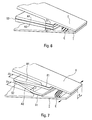
- Figure 6 is a perspective view at rest of a helicopter blade section in which is implanted the device according to a first embodiment.
- Figure 7 illustrates the operation of the device according to this first embodiment.
- Figure 8 shows the characteristic shear diagrams of the device implanted in the blade.
- Figure 9 is a section of the device in a helicopter blade according to a second embodiment.
- the sandwich structure planar actuator A according to the present invention and shown in FIG. 1 has a thickness t in the Z direction, a length L in the X direction and a width W in the Y direction.
- This actuator consists of following elements:
- a piezoelectric active plane layer 1 able to elongate or retract along the bisector of the X and Y directions when it is supplied with voltage.
- This piezoelectric layer consists of unidirectional piezoelectric rectangular fibers oriented along the bisector of the X and Y directions and supplied with voltage by electrodes 1a and 1b. The fibers are sandwiched between epoxy structural layers and polyamide films integrating inter-digitated electrodes perpendicular to the fibers.
- the assembly has a thickness of about 0.3 mm and an active rectangular surface of 85 ⁇ 57 mm 2 for example.
- the disadvantage of this type of layer is that it is very thin and therefore sensitive to buckling.
- Another disadvantage relates to its elongation in the X direction which can cause problems in the areas of bonding attachment areas with their supports, especially if they are very rigid. The shear stress can then cause the rupture of the glue joint.
- first fabric 2 On the top of the entire surface of said active plane layer is placed a first fabric 2 of 0.2 mm, for example of the taffeta type, whose fibers are made of high modulus material, such as for example HM carbon.
- This fabric has a frame and a chain respectively oriented in the direction X and the direction Y. The frame and the chain define a mesh of parallelograms juxtaposed.
- Two glue joints 4 and 5 are arranged between the three layers to bond them together. These glue joints have a thickness set at 0.1 mm by means of a flexible textile grid and a Young's modulus suitable so as to best transmit the shear displacement of said piezoelectric active planar layer 1 to tissues 2 and 3.
- An attachment zone S1 is oriented according to the weft of the tissues and extends along one end along the chain of these same tissues. It is located for example on an outer face of the actuator.
- the other attachment zone S2 is oriented according to the weft of the tissues and extends along the other end along the chain of these same tissues. It is located for example on the other outer face of the actuator.
- the operating principle of the actuator is that, when the active plane layer 1 is supplied with voltage by the electrodes 1a and 1b, it generates along the bisector X and Y directions, in the XY plane, an extension that is transmitted through at the glue joints to the two composite fabrics 2 and 3.
- the actuator elongates little in the direction X because the weft of the fabric is opposed. The glue joints are therefore little used. Similarly, the actuator elongates slightly in the Y direction because the warp of the fabric is opposed. The actuator is slightly deformed in the Z direction because it is symmetrical and the resultant of the forces involved is in the X-Y plane.
- Such an actuator was manufactured with, as an active plane layer, an active section MFC 85 ⁇ 57 ⁇ 0.3 mm 3 sandwiched between two SXM10 carbon fabrics and tested under +/- 750 volts.
- an alternative embodiment makes it possible to increase the displacement in shear.
- This actuator consists of the following elements:
- a fabric of 0.2 mm for example of the taffeta type, whose fibers are made of high modulus material, such as HM carbon.
- This layer of fabric is flat and has a frame and a chain respectively oriented in the direction X and the direction Y. The frame and the chain define a mesh of parallelograms juxtaposed.
- a first piezoelectric active plane layer adapted to elongate or retract along the bisector of the X and Y directions when it is supplied with voltage.
- This piezoelectric layer is of the same type as that of the preceding example. It thus generates a shear angle ⁇ with respect to the direction X.
- Two glue joints are arranged between the three layers to bind them together. These glue joints have a thickness set at 0.1 mm by means of a flexible textile grid and a Young's modulus suitable so as to best transmit the shear displacement of said actuators to said composite fabric.
- the first attachment zone is located on an outer face of the actuator. It is oriented according to the weft of the fabric and extends along one end along the chain of the same fabric.
- the second attachment zone is located on the other outer face of the actuator. It is oriented according to the weft of the fabric and extends along the other end along the chain of the same fabric.
- the two piezoelectric active plane layers of this actuator are simultaneously powered by the same voltage. They generate, according to the same bisector of the X and Y directions, in the X-Y plane, an extension which is transmitted thanks to the glue joints at the tissue layer.
- the parallelograms of the mesh of the fabric, solicited following the same diagonal, are deformed. This deformation is transformed into a shear ⁇ as in the previous example.
- the glue joints are not very stressed and the resultant of the forces involved is in the X-Y plane.
- Such an actuator was manufactured with an SXM10 carbon fabric sandwiched between two active section MFCs 85 ⁇ 57 ⁇ 0.3 mm 3 serving as active piezoelectric flat layers and was tested in operation with the same measuring means and in the same conditions than in Example 1.
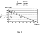
- Figure 3 illustrates an evaluation of the performance of such an actuator.
- the curve (II) is a line expressing the shear stiffness of the assembly.
- Curve (III) characterizes the actuator which is the assembly of the layer of fabric + glue with the 2 MFC.
- the structure must be symmetrical with respect to a median plane, in order to promote a plane shear deformation of the actuator.
- each flat layer of fabric that defines a parallelogram-shaped mesh must all be oriented respectively in the same two directions of their plane, parallel to the median plane.
- all the piezoelectric active planar layers must have, each in their plane, active directions parallel and in the same direction oriented along the same diagonal of the mesh in the form of a parallelogram.
- the two attachment zones must be located at opposite ends of the weft or warp of the fabric layers and be arranged respectively in the direction of the warp or weft of the fabric layers.
- the invention relates to a device consisting of the head-to-tail assembly of two actuators A1 and A2 identical to the actuator A described in the previous examples.
- the two actuators A1 and A2 are mounted as shown in Figure 4, one above the other, parallel to each other and glued by their respective attachment areas S2.
- a device can implement a combination of two non-strictly identical actuators. For example, it is possible to combine a first actuator according to example 1 with a second actuator having the same sandwich structure but, on the one hand, the width W along the Y direction is greater than that of the first actuator and whose on the other hand, the two attachment zones are situated on the same face of this second actuator.
- the resulting device then has two adjacent attachment areas accessible by a single face, which may be of practical interest for certain applications.
- a device according to the invention can advantageously be used in combination with a helicopter blade structure in order to make it undergo a torsion according to the span. Under these conditions, the system is no longer strictly plane during its operation but is slightly warped. However, this deformation is weak locally and does not fundamentally modify the operation of the device described in the preceding examples.
- the device of the invention can be disposed inside the profile of an open aircraft airfoil, and near its trailing edges.
- a bearing surface is said to be open when the intrados and extrados are not secured to each other near the trailing edge of the surface.
- the extrados trailing edges E and intrados I are provided with reinforcements vis-a-vis the attachment areas S1 of A1 and A2 of the device.
- the trailing edges are glued, or screwed, at the reinforcements to the attachment zones S1 of each of the identical actuators A1 and A2.
- the collages or screwings are distributed along the span, parallel to the X axis of FIG. 5.
- the zones S2 of A1 and A2 and the trailing edge are situated, according to the rope, on either side of the zones. S1 fixation of A1 and A2 from the device to the wing.
- the plane of symmetry of the device at rest is in the vicinity of the chord plane of the profile, therefore the neutral axis of bending. The device is thus subjected to very low stresses when the blade is biased in bending.
- the device closes continuously the span of the section of the bearing zone.
- a complementary connection can be made between the intrados and extrados trailing edges by means of a low modulus elastomer C bonded to a reinforcement of each of the trailing edges, or even directly between the attachment zones S1 of A1 and A2. of the device, because it is the rigidity in shear of the device which conditions the torsional rigidity of the bearing zone.
- the principle of the device thus implanted is identical to that of Example 2.
- the amplitude d of the total shear displacement of the device between the trailing edges is equal to the sum of the shear displacement amplitudes of each actuator, as indicated on FIG. Figure 7.
- the device of the invention can integrate the trailing edge itself, the two actuators respectively constituting the parts of the extrados and the intrados immediately adjacent to the trailing edge.
- the planes of symmetry of the two actuators are no longer parallel.
- the actuators A1 and A2 of the device are assembled by their respective attachment zones S1 so as to form between them the desired angle for the trailing edge of the blade.
- the actuator A1 is bonded by its fastening zone S2 to the upper surface of the airfoil at the upper surface of the aerodynamic profile and the simple actuator A2 is bonded by its fastening area S2 to the intrados on the trailing edge side. to the lower skin I of the aerodynamic profile.
- the zones S1 and the trailing edge are situated, according to the rope, on the same side of the attachment zones S2 of A1 and A2 of the device to the wing.
- a connection between the intrados and extrados leakage edges can be achieved by means of a low modulus elastomer C bonded for example at the inner faces of the double actuator.
- the device closes continuously following the span of the section of the bearing surface and performs a "composite" assembly so as to stiffen the actuator to prevent buckling.
Abstract
Description
La présente invention concerne un actionneur actif apte à fournir un déplacement transverse de cisaillement dans un plan, un dispositif mettant en oeuvre deux actionneurs de ce type et son application à la torsion de structure.The present invention relates to an active actuator capable of providing a transverse displacement of shear in a plane, a device implementing two actuators of this type and its application to the torsion structure.
Elle porte plus particulièrement sur un actionneur actif plan à structure sandwich comportant au moins une couche plane piézoélectrique ayant une direction active superposée et solidarisée à au moins une couche plane passive de tissu à chaîne et trame rigides formant un maillage. La direction active de la couche piézoélectrique est orientée de façon particulière par rapport au maillage des couches de tissu.More particularly, it relates to a planar active actuator with a sandwich structure comprising at least one piezoelectric flat layer having an active superimposed direction and secured to at least one passive flat layer of rigid warp and weft fabric forming a mesh. The active direction of the piezoelectric layer is oriented in a particular way with respect to the mesh of the fabric layers.
L'invention s'applique à la torsion active de structures comme, par exemple, une pale d'hélicoptère.The invention applies to active torsion of structures such as, for example, a helicopter blade.
En aéronautique, le souci d'améliorer la maniabilité, la sécurité ou de diminuer les nuisances sonores conduit les concepteurs d'aéronef à mettre en oeuvre de plus en plus souvent des éléments de voilure actifs. Ces éléments sont aptes à se déformer de façon contrôlée en réponse à une consigne précise, afin de modifier le comportement des aéronefs dans leur environnement.In aeronautics, the desire to improve maneuverability, safety or reduce noise nuisance leads aircraft designers to implement more and more often active wing elements. These elements are able to deform in a controlled manner in response to a specific instruction, in order to modify the behavior of the aircraft in their environment.
Ainsi, le gauchissement contrôlé de surfaces portantes d'aéronefs a fait l'objet de nombreuses études et a donné lieu à la réalisation d'actionneurs permettant un déplacement relatif de la surface supérieure ou extrados par rapport à la surface inférieure ou intrados.Thus, the controlled warping of airfoils of aircraft has been the subject of numerous studies and has led to the production of actuators allowing relative movement of the upper surface or extrados relative to the lower surface or intrados.
Outre les actionneurs mécaniques et hydrauliques comme présenté par
Dans le brevet anglais
Dans les travaux de Matthew L. Wilbur, une pale d'hélicoptère est équipée, à six endroits répartis selon son envergure tous situés dans la zone d'épaisseur maximale quasi plane, de deux actionneurs piézoélectriques, un dans l'extrados, l'autre dans l'intrados. Chaque actionneur comporte deux couches piézoélectriques du type MFC (Macro Fiber Composite), aptes chacune à s'allonger ou se contracter selon une direction active. Une première couche centrale de tissu de verre est prise en sandwich entre deux couches piézoélectriques. Les directions actives des couches piézoélectriques sont orientées respectivement selon la chaîne et la trame du tissu de verre. Ce premier sandwich est lui même pris en sandwich entre deux autres couches de tissu de verre dont la chaîne et la trame sont orientées selon les diagonales de la chaîne et de la trame du tissu de la couche centrale, donc des directions actives. C'est ce sandwich à cinq couches qui constitue un actionneur.In the work of Matthew L. Wilbur, a helicopter blade is equipped, at six locations distributed according to its wingspan all located in the zone of maximum thickness almost plane, of two piezoelectric actuators, one in the extrados, the other in the intrados. Each actuator comprises two piezoelectric layers of the MFC (Macro Fiber Composite) type, each capable of lengthening or contracting in an active direction. A first central layer of glass fabric is sandwiched between two piezoelectric layers. The active directions of the piezoelectric layers are oriented respectively along the warp and weft of the glass fabric. This first sandwich is itself sandwiched between two other layers of glass fabric whose warp and weft are oriented along the diagonals of the warp and weft of the fabric of the central layer, and thus active directions. It is this five-layer sandwich that constitutes an actuator.
Lorsqu'un actionneur quasi plan est activé, il se déforme spontanément en torsion, induisant directement le gauchissement de la pale. Le fait d'avoir disposé des ensembles à l'intrados et à l'extrados amplifie le gauchissement de la pale. Outre la difficulté d'implantation de tels ensembles dans la structure de la pale, ils sont situés dans une section fermée, dite « D-spar », présentant une rigidité en torsion élevée qui oppose une forte résistance aux déformations des actionneurs, créant ainsi de fortes contraintes entre les couches qui les constituent. De plus, ces actionneurs étant situés sur les peaux intrados et extrados, au niveau de l'épaisseur maximale du profil, ils subissent donc aussi de fortes contraintes lorsque la pale est sollicitée en flexion de battement.When a quasi-plane actuator is activated, it spontaneously deforms in torsion, directly inducing the warping of the blade. The fact of having the sets on the intrados and the extrados amplifies the warping of the blade. In addition to the difficulty of installing such assemblies in the structure of the blade, they are located in a closed section, called "D-spar", having a high torsional stiffness which opposes a high resistance to the deformations of the actuators, thus creating strong constraints between the layers that constitute them. Moreover, these actuators being located on the intrados and extrados skins, at the level of the maximum thickness of the profile, they therefore also suffer from high stresses when the blade is subjected to bending bending.
Afin de limiter cette résistance, dans le brevet français au nom du demandeur (
Il était donc souhaitable pour le demandeur de pouvoir mettre en oeuvre un dispositif qui referme continûment la section de la pale, assure une forte rigidité en torsion, ait des contraintes internes limitées lorsque la pale est soumise à des charges extérieures et permette une course importante entre les deux bords de fuite de l'extrados et de l'intrados selon l'envergure.It was therefore desirable for the applicant to be able to implement a device that closes the section of the blade continuously, provides high torsional stiffness, has limited internal stresses when the blade is subjected to external loads and allows a large stroke between the two trailing edges of the extrados and the intrados according to the span.
La présente invention a pour objet un actionneur plan apte à se déformer en cisaillement et un dispositif mettant en oeuvre deux actionneurs selon l'invention montés tête-bêche aptes à se déformer en cisaillement chacun dans leur plan. Elle concerne aussi l'implantation particulière d'un tel dispositif dans une structure de pale d'hélicoptère dont il referme continûment la section initialement ouverte.The present invention relates to a planar actuator adapted to deform in shear and a device using two actuators according to the invention mounted head to tail able to deform in shear each in their plane. It also relates to the particular implementation of such a device in a helicopter blade structure which it closes continuously the initially open section.
L'actionneur, élément constitutif du dispositif de l'invention, est de type plan à structure sandwich comportant deux zones de fixation destinées à transmettre le déplacement relatif en cisaillement généré par l'actionneur et au moins trois couches planes superposées comprenant au moins une couche d'un tissu dont la chaîne et la trame sont constituées de fibres rigides disposées selon deux directions du plan, formant un maillage de parallélogrammes juxtaposés, et au moins une couche plane active piézoélectrique apte à s'allonger ou se rétracter selon une direction active, chaque face d'une couche étant collée sur toute sa surface à une face de la couche adjacente. Dans l'actionneur de l'invention, la structure sandwich est symétrique par rapport au plan médian de l'actionneur favorisant ainsi une déformation plane en cisaillement, la direction active de chaque couche plane piézoélectrique est orientée selon une seule et même diagonale du maillage de chaque couche de tissu dont la chaîne et la trame sont orientées selon deux directions du plan, les zones de fixation de l'actionneur, de forme allongée selon une première des deux directions du plan, sont disposées le long des extrémités opposées de l'actionneur selon la seconde direction du plan, ce grâce à quoi, chaque couche plane de tissu étant sollicitée selon une seule diagonale du maillage, les parallélogrammes se déforment entraînant le déplacement dans le plan des zones de fixation parallèlement l'une à l'autre selon la première direction du plan.The actuator, which is a constituent element of the device of the invention, is of planar type with a sandwich structure comprising two attachment zones intended to transmit the relative displacement in shear generated by the actuator and at least three superposed flat layers comprising at least one layer. a fabric whose warp and weft consist of rigid fibers arranged in two directions of the plane, forming a mesh of juxtaposed parallelograms, and at least one piezoelectric active plane layer able to elongate or retract in an active direction, each face of a layer being adhered over its entire surface to one side of the adjacent layer. In the actuator of the invention, the sandwich structure is symmetrical relative to the median plane of the actuator thus favoring a plane shear deformation, the active direction of each piezoelectric plane layer is oriented along one and the same diagonal of the mesh of each layer of fabric whose warp and weft are oriented in two directions of the plane, the attachment zones of the actuator, of elongate shape along a first of the two directions of the plane, are arranged along the opposite ends of the actuator according to the second direction of the plane, thanks to which, each flat layer of fabric being solicited along a single diagonal of the mesh, the parallelograms are deformed causing the displacement in the plane of the fastening zones parallel to one another according to the first direction of the plan.
Selon une première réalisation, l'actionneur comporte deux couches de tissu prenant en sandwich une couche plane active.In a first embodiment, the actuator comprises two layers of fabric sandwiching an active planar layer.
Selon une deuxième réalisation, l'actionneur comporte une couche de tissu prise en sandwich entre deux couches planes actives qui s'allongent et se rétractent ensemble.In a second embodiment, the actuator comprises a layer of fabric sandwiched between two active planar layers that elongate and retract together.
L'invention concerne aussi un dispositif comportant l'empilement de deux actionneurs montés tête-bêche, deux des zones de fixation en vis-à-vis des actionneurs étant solidarisées et les deux directions actives n'étant pas parallèles, les deux autres zones de fixation des actionneurs laissées libres se déplacent parallèlement en sens inverse selon la première direction du plan avec une amplitude égale à la somme des déplacements des deux actionneurs.The invention also relates to a device comprising the stack of two actuators mounted head to tail, two of the fastening zones vis-à-vis the actuators being secured and the two active directions are not parallel, the other two zones of fixing the actuators left free move parallel in the opposite direction in the first direction of the plane with an amplitude equal to the sum of the movements of the two actuators.
L'invention concerne encore l'implantation du dispositif dans une structure de pale d'hélicoptère, une zone de fixation libre étant solidaire de l'extrados, l'autre zone de fixation libre étant solidaire de l'intrados.The invention also relates to the implantation of the device in a helicopter blade structure, a free fastening zone being integral with the extrados, the other free fastening zone being integral with the intrados.
Selon une première réalisation d'implantation, le dispositif est situé entre l'extrados et l'intrados, à l'intérieur de la pale, dans le plan de la corde. Deux zones de fixation sont directement solidarisées l'une à l'autre, les deux autres zones de fixation sont solidarisées respectivement à l'intrados et à l'extrados, à proximité immédiate du bord de fuite. La hauteur du dispositif est alors minimale, ce qui facilite son intégration sans pour autant en limiter la course.According to a first embodiment of implantation, the device is located between the extrados and the intrados, inside the blade, in the plane of the rope. Two attachment areas are directly secured to one another, the other two attachment areas are secured respectively to the intrados and extrados, in the immediate vicinity of the trailing edge. The height of the device is then minimal, which facilitates its integration without limiting the stroke.
Selon une deuxième réalisation d'implantation, le dispositif est placé dans le prolongement respectivement de l'intrados et de l'extrados. Il constitue le bord de fuite de la pale, dont il referme continûment la section initialement ouverte. I1 est alors composé de deux actionneurs plans dont deux zones de fixation sont solidarisées l'une à l'autre, les plans respectifs des actionneurs formant entre eux l'angle du bord de fuite souhaité pour la pale, les deux autres zones de fixation sont solidarisées respectivement aux extrémités libres de l'intrados et de l'extrados.According to a second embodiment of implantation, the device is placed in the extension respectively of the intrados and extrados. It constitutes the trailing edge of the blade, which it closes continuously the section initially opened. I1 is then composed of two planar actuators whose two fixing zones are secured to one another, the respective planes of the actuators forming between them the angle of the desired trailing edge for the blade, the two other fixing zones are secured respectively to the free ends of the intrados and extrados.
Les figures du dessin annexé feront bien comprendre comment l'invention peut être réalisée. Sur ces figures, des références identiques désignent des éléments semblables.The figures of the appended drawing will make it clear how the invention can be realized. In these figures, identical references designate similar elements.
La figure 1 est une vue schématique d'un actionneur conforme à l'invention, au repos.Figure 1 is a schematic view of an actuator according to the invention, at rest.
La figure 2 illustre la déformation en cisaillement de l'actionneur de la figure 1, lorsqu'il est activé.Figure 2 illustrates the shear deformation of the actuator of Figure 1, when activated.
La figure 3 présente les diagrammes de cisaillement caractéristiques d'un actionneur de l'invention.Figure 3 shows the characteristic shear diagrams of an actuator of the invention.
La figure 4 est une vue schématique d'un dispositif conforme à l'invention, au repos.Figure 4 is a schematic view of a device according to the invention, at rest.
La figure 5 représente la déformation en cisaillement du dispositif de la figure 4, lorsqu'il est activé.Figure 5 shows the shear deformation of the device of Figure 4, when activated.
La figure 6 est une vue perspective au repos d'un tronçon de pale d'hélicoptère dans lequel est implanté le dispositif selon une première réalisation.Figure 6 is a perspective view at rest of a helicopter blade section in which is implanted the device according to a first embodiment.
La figure 7 illustre le fonctionnement du dispositif selon cette première réalisation.Figure 7 illustrates the operation of the device according to this first embodiment.
La figure 8 montre les diagrammes de cisaillement caractéristiques du dispositif implanté dans la pale.Figure 8 shows the characteristic shear diagrams of the device implanted in the blade.
La figure 9 est une coupe du dispositif dans une pale d'hélicoptère selon une deuxième réalisation.Figure 9 is a section of the device in a helicopter blade according to a second embodiment.
L'actionneur plan à structure sandwich A, conforme à la présente invention et montré par la figure 1 présente une épaisseur t suivant la direction Z, une longueur L suivant la direction X et une largeur W suivant la direction Y. Cet actionneur est constitué des éléments suivants :The sandwich structure planar actuator A according to the present invention and shown in FIG. 1 has a thickness t in the Z direction, a length L in the X direction and a width W in the Y direction. This actuator consists of following elements:
Dans le plan central se trouve une couche plane active piézoélectrique 1 apte à s'allonger ou se rétracter suivant la bissectrice des directions X et Y lorsqu'elle est alimentée en tension. Cette couche piézoélectrique est constituée de fibres rectangulaires unidirectionnelles piézoélectriques orientées suivant la bissectrice des directions X et Y et alimentées en tension par des électrodes 1a et 1b. Les fibres sont prises en sandwich entre des couches d'époxy structural et des films polyamides intégrant les électrodes inter-digitées perpendiculaires aux fibres. L'ensemble a une épaisseur d'environ 0.3 mm et une surface rectangulaire active de 85 x 57 mm2 par exemple. L'inconvénient de ce type de couche est qu'elle est très mince et donc sensible au flambage. Un autre inconvénient concerne son allongement suivant la direction X qui peut poser des problèmes dans les zones de collage des zones de fixation avec leur supports, en particulier si ceux-ci sont très rigides. La contrainte de cisaillement peut alors entraîner la rupture du joint de colle.In the central plane is a piezoelectric
Sur le dessus de toute la surface de ladite couche plane active est placé un premier tissu 2 de 0.2 mm, par exemple de type taffetas, dont les fibres sont en matériau à haut module, comme par exemple du carbone HM. Ce tissu a une trame et une chaîne orientées respectivement selon la direction X et la direction Y. La trame et la chaîne définissent un maillage de parallélogrammes juxtaposés.On the top of the entire surface of said active plane layer is placed a
Sur le dessous de toute la surface de ladite couche plane active est placé un second tissu 3 identique au premier tissu 2 et orienté de la même façon.On the underside of the entire surface of said active planar layer is placed a
Deux joints de colle 4 et 5 sont disposés entre les trois couches pour les lier entre elles. Ces joints de colle ont une épaisseur réglée à 0.1 mm au moyen d'une grille textile souple et un module de Young approprié de façon à transmettre au mieux le déplacement de cisaillement de ladite couche plane active piézoélectrique 1 audits tissus 2 et 3.Two
Une zone de fixation S1 est orientée selon la trame des tissus et s'étend le long d'une extrémité selon la chaîne de ces mêmes tissus. Elle est située par exemple sur une face extérieure de l'actionneur.An attachment zone S1 is oriented according to the weft of the tissues and extends along one end along the chain of these same tissues. It is located for example on an outer face of the actuator.
L'autre zone de fixation S2 est orientée selon la trame des tissus et s'étend le long de l'autre extrémité selon la chaîne de ces mêmes tissus. Elle est située par exemple sur l'autre face extérieure de l'actionneur.The other attachment zone S2 is oriented according to the weft of the tissues and extends along the other end along the chain of these same tissues. It is located for example on the other outer face of the actuator.
Le principe de fonctionnement de l'actionneur est que, lorsque la couche plane active 1 est alimentée en tension par les électrodes 1a et 1b, elle génère selon la bissectrice des directions X et Y, dans le plan X-Y, une extension qui se transmet grâce aux joints de colle aux deux tissus composites 2 et 3. Les parallélogrammes du maillage des tissus, sollicités suivant la même diagonale, se déforment. Cette déformation se transforme en un angle de cisaillement γ par rapport à la direction Y comme illustré par la figure 2 et la couche plane active 1 fournit un déplacement en cisaillement Xγ = γ × W suivant l'axe X comme indiqué sur ladite figure 2.The operating principle of the actuator is that, when the
L'actionneur s'allonge peu suivant la direction X car la trame du tissu s'y oppose. Les joints de colle sont donc peu sollicités. De même, l'actionneur s'allonge peu suivant la direction Y car la chaîne du tissu s'y oppose. L'actionneur se déforme peu selon la direction Z car il est symétrique et la résultante des forces mises en jeu est dans le plan X-Y.The actuator elongates little in the direction X because the weft of the fabric is opposed. The glue joints are therefore little used. Similarly, the actuator elongates slightly in the Y direction because the warp of the fabric is opposed. The actuator is slightly deformed in the Z direction because it is symmetrical and the resultant of the forces involved is in the X-Y plane.
Un tel actionneur a été fabriqué avec, comme couche plane active, une MFC de section active 85 × 57 × 0.3 mm3 prise en sandwich entre deux tissus de carbone SXM10 et a été testé en fonctionnement sous +/-750 Volts.Such an actuator was manufactured with, as an active plane layer, an active section MFC 85 × 57 × 0.3 mm 3 sandwiched between two SXM10 carbon fabrics and tested under +/- 750 volts.
Au moyen d'une rosette de trois jauges collée au centre de la couche plane active, il a été mesuré :
- les déformations suivant la direction X ;
- les déformations suivant la direction Y ;
- les déformations de cisaillement γ.
- deformations along the X direction;
- deformations along the Y direction;
- Shear deformation γ.
Il a été aussi mesuré au moyen d'un capteur optique les déplacements des quatre coins de l'actionneur qui, rapportés à sa largeur W, permettent de déduire les déformations en cisaillement.It has also been measured by means of an optical sensor displacements of the four corners of the actuator which, related to its width W, allow to deduce the shear deformations.
Les résultats sont présentés dans le tableau 1 dans lequel 1µdef=10-6 mètre par mètre.
Toujours dans le cadre d'un actionneur à trois couches, une variante de réalisation permet d'accroître le déplacement en cisaillement.Still in the context of a three-layer actuator, an alternative embodiment makes it possible to increase the displacement in shear.
Cet actionneur est constitué des éléments suivants :This actuator consists of the following elements:
Au centre, est placé un tissu de 0.2 mm, par exemple de type taffetas, dont les fibres sont en matériau à haut module, comme en carbone HM. Cette couche de tissu est plane et a une trame et une chaîne orientées respectivement selon la direction X et la direction Y. La trame et la chaîne définissent un maillage de parallélogrammes juxtaposés.In the center, is placed a fabric of 0.2 mm, for example of the taffeta type, whose fibers are made of high modulus material, such as HM carbon. This layer of fabric is flat and has a frame and a chain respectively oriented in the direction X and the direction Y. The frame and the chain define a mesh of parallelograms juxtaposed.
Sur le dessus de toute la surface de ladite couche de tissu est placée une première couche plane active piézoélectrique apte à s'allonger ou se rétracter suivant la bissectrice des directions X et Y lorsqu'elle est alimentée en tension. Cette couche piézoélectrique est du même type que celle de l'exemple précédent. Elle génère donc un angle de cisaillement γ par rapport à la direction X.On the top of the entire surface of said fabric layer is placed a first piezoelectric active plane layer adapted to elongate or retract along the bisector of the X and Y directions when it is supplied with voltage. This piezoelectric layer is of the same type as that of the preceding example. It thus generates a shear angle γ with respect to the direction X.
Sur le dessous de toute la surface de ladite couche de tissu est placée une seconde couche plane active piézoélectrique identique à la première et orientée de la même façon.On the underside of the entire surface of said fabric layer is placed a second piezoelectric active plane layer identical to the first and oriented in the same way.
Deux joints de colle sont disposés entre les trois couches pour les lier entre elles. Ces joints de colle ont une épaisseur réglée à 0.1 mm au moyen d'une grille textile souple et un module de Young approprié de sorte à transmettre au mieux le déplacement de cisaillement desdits actionneurs audit tissu composite.Two glue joints are arranged between the three layers to bind them together. These glue joints have a thickness set at 0.1 mm by means of a flexible textile grid and a Young's modulus suitable so as to best transmit the shear displacement of said actuators to said composite fabric.
La première zone de fixation est située sur une face extérieure de l'actionneur. Elle est orientée selon la trame du tissu et s'étend le long d'une extrémité selon la chaîne de ce même tissu.The first attachment zone is located on an outer face of the actuator. It is oriented according to the weft of the fabric and extends along one end along the chain of the same fabric.
La seconde zone de fixation est située sur l'autre face extérieure de l'actionneur. Elle est orientée selon la trame du tissu et s'étend le long de l'autre extrémité selon la chaîne de ce même tissu.The second attachment zone is located on the other outer face of the actuator. It is oriented according to the weft of the fabric and extends along the other end along the chain of the same fabric.
En fonctionnement, les deux couches planes actives piézoélectriques de cet actionneur sont alimentés simultanément par une même tension. Elles génèrent selon une même bissectrice des directions X et Y, dans le plan X-Y, une extension qui se transmet grâce aux joints de colle à la couche de tissu. Les parallélogrammes du maillage du tissu, sollicités suivant la même diagonale, se déforment. Cette déformation se transforme en un cisaillement γ comme dans l'exemple précédent. Là encore, les joints de colle sont peu sollicités et la résultante des forces mises en jeu est dans le plan X-Y.In operation, the two piezoelectric active plane layers of this actuator are simultaneously powered by the same voltage. They generate, according to the same bisector of the X and Y directions, in the X-Y plane, an extension which is transmitted thanks to the glue joints at the tissue layer. The parallelograms of the mesh of the fabric, solicited following the same diagonal, are deformed. This deformation is transformed into a shear γ as in the previous example. Here again, the glue joints are not very stressed and the resultant of the forces involved is in the X-Y plane.
Un tel actionneur a été fabriqué avec un tissu de carbone SXM10 pris en sandwich entre deux MFC de section active 85 × 57 × 0.3 mm3 servant de couches planes actives piézoélectriques et a été testé en fonctionnement avec les mêmes moyens de mesure et dans les mêmes conditions que dans l'exemple 1.Such an actuator was manufactured with an SXM10 carbon fabric sandwiched between two active section MFCs 85 × 57 × 0.3 mm 3 serving as active piezoelectric flat layers and was tested in operation with the same measuring means and in the same conditions than in Example 1.
Les résultats sont présentés dans le tableau 2, dans lequel 1µdef=10-6 mètre par mètre.
La figure 3 illustre une évaluation des performances d'un tel actionneur.Figure 3 illustrates an evaluation of the performance of such an actuator.
Pour les MFC nues, la courbe (I) est la droite de l'angle de cisaillement γ crête à crête mesuré sur une MFC alimentée sous +/-500V en fonction de la force de cisaillement F établie à partir de la pente de raideur calculée en cisaillement. Si γ = 0, la force de cisaillement est dite de blocage car elle est telle qu'elle fait perdre toute la course à vide qui est γmax (320µdéf) pour F=0.For bare MFCs, the curve (I) is the straight line of the peak-to-peak γ shear angle measured on an MFC fed at +/- 500V as a function of the shear force F established from the calculated stiffness slope. in shear. If γ = 0, the shear force is called blocking because it is such that it makes lose all the empty stroke which is γmax (320μdef) for F = 0.
Pour le tissu de carbone et les deux joints de colle, la courbe (II) est une droite exprimant la raideur en cisaillement de l'ensemble.For the carbon fabric and the two glue joints, the curve (II) is a line expressing the shear stiffness of the assembly.
La courbe (III) caractérise l'actionneur qui est l'assemblage de la couche de tissu + colle avec les 2 MFC.Curve (III) characterizes the actuator which is the assembly of the layer of fabric + glue with the 2 MFC.
En complément à ces deux exemples, il est possible de mettre en oeuvre un nombre de couches planes plus important. Cependant, afin d'être conforme à l'invention la structure des différentes variantes réalisées doit satisfaire simultanément à plusieurs caractéristiques essentielles.In addition to these two examples, it is possible to implement a larger number of plane layers. However, in order to be in accordance with the invention, the structure of the different variants made must simultaneously satisfy several essential characteristics.
Tout d'abord, la structure doit être symétrique par rapport à un plan médian, ceci afin de favoriser une déformation en cisaillement plane de l'actionneur.First, the structure must be symmetrical with respect to a median plane, in order to promote a plane shear deformation of the actuator.
Ensuite, la trame et la chaîne de chaque couche plane de tissu qui définissent une maille en forme de parallélogramme, doivent toutes être orientées selon respectivement les deux mêmes directions de leur plan, parallèle au plan médian.Then, the weft and warp of each flat layer of fabric that defines a parallelogram-shaped mesh, must all be oriented respectively in the same two directions of their plane, parallel to the median plane.
De plus, toutes les couches planes actives piézoélectriques doivent avoir, chacune dans leur plan, des directions actives parallèles et de même sens orientées selon la même diagonale de la maille en forme de parallélogramme.In addition, all the piezoelectric active planar layers must have, each in their plane, active directions parallel and in the same direction oriented along the same diagonal of the mesh in the form of a parallelogram.
Enfin, les deux zones de fixation doivent être situées aux extrémités opposées de la trame ou de la chaîne des couches de tissu et être disposées respectivement selon la direction de la chaîne ou de la trame des couches de tissu.Finally, the two attachment zones must be located at opposite ends of the weft or warp of the fabric layers and be arranged respectively in the direction of the warp or weft of the fabric layers.
L'invention porte sur un dispositif composé de l'assemblage tête-bêche de deux actionneurs A1 et A2 identiques à l'actionneur A décrit dans les exemples précédents. Les deux actionneurs A1 et A2 sont montés comme indiqué sur la figure 4, l'un au-dessus de l'autre, parallèles l'un à l'autre et collés par leurs zones de fixation S2 respectives.The invention relates to a device consisting of the head-to-tail assembly of two actuators A1 and A2 identical to the actuator A described in the previous examples. The two actuators A1 and A2 are mounted as shown in Figure 4, one above the other, parallel to each other and glued by their respective attachment areas S2.
Le principe de fonctionnement de l'invention est que, lorsque le premier actionneur conforme à celui de l'exemple 1 ou 2 est activé, il génère dans le plan X-Y et à 45° une extension qui se transmet au tissu dont le maillage sollicité suivant la première diagonale se déforme en parallélogramme. Cette déformation se transforme en un cisaillement γ et le premier actionneur fournit un déplacement en cisaillement Xγ1 = γ × W suivant l'axe X comme le montre la figure 5.The operating principle of the invention is that, when the first actuator according to that of example 1 or 2 is activated, it generates in the XY plane and at 45 ° an extension which is transmitted to the fabric whose mesh solicited next the first diagonal is deformed into a parallelogram. This deformation is transformed into a shear γ and the first actuator provides shear displacement X γ1 = γ × W along the X axis as shown in FIG.
De même, lorsque le deuxième actionneur est activé, il génère dans le plan X-Y et à 135° une extension qui se transmet au tissu dont le maillage sollicité suivant la deuxième diagonale se déforme en parallélogramme. Cette déformation se transforme en un cisaillement -γ et le deuxième actionneur A2 fournit un déplacement en cisaillement Xγ2 = -γ × W suivant l'axe X. Ce déplacement de cisaillement est opposé au déplacement de cisaillement du premier actionneur A1.Likewise, when the second actuator is activated, it generates in the XY plane and at 135 ° an extension which is transmitted to the fabric whose mesh biased along the second diagonal is deformed into a parallelogram. This deformation is transformed into a shear -γ and the second actuator A2 provides a shift in shear X γ2 = -γ × W along the X axis. This shear displacement is opposite the shear displacement of the first actuator A1.
L'amplitude d du déplacement total de cisaillement du dispositif entre les zones de fixation S1 respectives est égale à la somme des amplitudes des déplacement de cisaillement de chaque actionneur, soit d= Xγ1 - Xγ2 et comme dans l'exemple les actionneurs sont identiques, d = 2γ x W comme indiqué sur la figure 5.The amplitude d of the total shear displacement of the device between the respective attachment zones S1 is equal to the sum of the shear displacement amplitudes of each actuator, ie d = X γ1 -X γ2 and, as in the example, the actuators are identical, d = 2γ x W as shown in FIG.
Un dispositif selon l'invention peut mettre en oeuvre une combinaison de deux actionneurs non strictement identiques. Par exemple, il est possible de combiner un premier actionneur conforme à l'exemple 1 avec un second actionneur ayant la même structure sandwich mais dont, d'une part, la largeur W suivant la direction Y est supérieure à celle du premier actionneur et dont, d'autre part, les deux zones de fixation sont situées sur la même face de ce second actionneur.A device according to the invention can implement a combination of two non-strictly identical actuators. For example, it is possible to combine a first actuator according to example 1 with a second actuator having the same sandwich structure but, on the one hand, the width W along the Y direction is greater than that of the first actuator and whose on the other hand, the two attachment zones are situated on the same face of this second actuator.
Le dispositif obtenu présente alors deux zones de fixation adjacentes accessibles par une seule face, ce qui peut présenter un intérêt pratique pour certaines applications.The resulting device then has two adjacent attachment areas accessible by a single face, which may be of practical interest for certain applications.
Un dispositif selon l'invention peut être utilisé avantageusement en combinaison avec une structure de pale d'hélicoptère afin de lui faire subir une torsion selon l'envergure. Dans ces conditions, le système n'est plus strictement plan au cours de son fonctionnement mais est légèrement gauchi. Cependant cette déformation est faible localement et ne modifie pas fondamentalement le fonctionnement du dispositif décrit dans les exemples précédents.A device according to the invention can advantageously be used in combination with a helicopter blade structure in order to make it undergo a torsion according to the span. Under these conditions, the system is no longer strictly plane during its operation but is slightly warped. However, this deformation is weak locally and does not fundamentally modify the operation of the device described in the preceding examples.
Comme montré sur la figure 6, le dispositif de l'invention peut être disposé à l'intérieur du profil d'une surface portante ouverte d'aéronef, et à proximité de ses bords de fuite. Une surface portante est dite ouverte lorsque l'intrados et l'extrados ne sont pas solidarisés entre eux à proximité du bord de fuite de la surface. Les bords de fuite extrados E et intrados I sont munis de renforts en vis-à-vis des zones de fixation S1 de A1 et de A2 du dispositif. Les bords de fuite sont collés, ou vissés, au niveau des renforts aux zones de fixation S1 de chacun des actionneurs identiques A1 et A2. Les collages ou vissages sont répartis suivant l'envergure, parallèle à l'axe X de la figure 5. Les zones S2 de A1 et de A2 et le bord de fuite sont situés, selon la corde, de part et d'autre des zones de fixation S1 de A1 et de A2 du dispositif à la voilure. Le plan de symétrie du dispositif au repos se situe au voisinage du plan de corde du profil, donc de l'axe neutre de flexion. Le dispositif n'est ainsi soumis qu'à de très faibles contraintes lorsque la pale est sollicitée en flexion.As shown in FIG. 6, the device of the invention can be disposed inside the profile of an open aircraft airfoil, and near its trailing edges. A bearing surface is said to be open when the intrados and extrados are not secured to each other near the trailing edge of the surface. The extrados trailing edges E and intrados I are provided with reinforcements vis-a-vis the attachment areas S1 of A1 and A2 of the device. The trailing edges are glued, or screwed, at the reinforcements to the attachment zones S1 of each of the identical actuators A1 and A2. The collages or screwings are distributed along the span, parallel to the X axis of FIG. 5. The zones S2 of A1 and A2 and the trailing edge are situated, according to the rope, on either side of the zones. S1 fixation of A1 and A2 from the device to the wing. The plane of symmetry of the device at rest is in the vicinity of the chord plane of the profile, therefore the neutral axis of bending. The device is thus subjected to very low stresses when the blade is biased in bending.
Le dispositif referme continûment suivant l'envergure la section de la zone portante. Cependant, une liaison complémentaire peut être réalisée entre les bords de fuite intrados et extrados au moyen d'un élastomère C à faible module collé sur un renfort de chacun des bords de fuite, voire directement entre les zones de fixation S1 de A1 et de A2 du dispositif, car c'est la rigidité en cisaillement du dispositif qui conditionne la rigidité en torsion de la zone portante.The device closes continuously the span of the section of the bearing zone. However, a complementary connection can be made between the intrados and extrados trailing edges by means of a low modulus elastomer C bonded to a reinforcement of each of the trailing edges, or even directly between the attachment zones S1 of A1 and A2. of the device, because it is the rigidity in shear of the device which conditions the torsional rigidity of the bearing zone.
Le principe du dispositif ainsi implanté est identique à celui de l'exemple 2. L'amplitude d du déplacement total de cisaillement du dispositif entre les bords de fuite est égale à la somme des amplitudes des déplacement de cisaillement de chaque actionneur, comme indiqué sur la figure 7.The principle of the device thus implanted is identical to that of Example 2. The amplitude d of the total shear displacement of the device between the trailing edges is equal to the sum of the shear displacement amplitudes of each actuator, as indicated on FIG. Figure 7.
La figure 8 illustre une évaluation des performances d'un tel dispositif.
- La courbe (I) caractérise le dispositif composé seulement des deux actionneurs simples en série définis précédemment. Les déplacements sont exprimés en µm. Le dispositif est alimenté sous +1500/-500 Volts ;
- La courbe (II) caractérise la raideur en cisaillement d'une section de pale (corde 141.5 mm) ouverte au bord de fuite. La structure interne est de type classique. La force de cisaillement est celle qu'il faut appliquer au bords de fuite pour les déplacer l'un par rapport à l'autre ;
- La courbe (III) caractérise l'assemblage pale et dispositif assemblés.
- The curve (I) characterizes the device consisting only of the two simple actuators in series defined above. The displacements are expressed in μm. The device is powered under + 1500 / -500 Volts;
- Curve (II) characterizes the shear stiffness of a section of blade (rope 141.5 mm) open at the trailing edge. The internal structure is of a conventional type. The shear force is that which must be applied to the trailing edges to move them relative to each other;
- The curve (III) characterizes the assembled blade and device assembly.
Comme montré sur la figure 9, le dispositif de l'invention peut intégrer le bord de fuite lui-même, les deux actionneurs constituant respectivement les parties de l'extrados et de l'intrados immédiatement voisines du bord de fuite. Les plans de symétrie des deux actionneurs ne sont plus parallèles. Les actionneurs A1 et A2 du dispositif sont assemblés par leurs zones de fixation S1 respectives de façon à former entre eux l'angle souhaité pour le bord de fuite de la pale. L'actionneur A1 est collé par sa zone de fixation S2 à l'extrados coté bord de fuite à la peau extrados E du profil aérodynamique et l'actionneur simple A2 est collé par sa zone de fixation S2 à l'intrados coté bord de fuite à la peau intrados I du profil aérodynamique. Les zones S1 et le bord de fuite sont situés, selon la corde, du même coté des zones de fixation S2 de A1 et de A2 du dispositif à la voilure.As shown in FIG. 9, the device of the invention can integrate the trailing edge itself, the two actuators respectively constituting the parts of the extrados and the intrados immediately adjacent to the trailing edge. The planes of symmetry of the two actuators are no longer parallel. The actuators A1 and A2 of the device are assembled by their respective attachment zones S1 so as to form between them the desired angle for the trailing edge of the blade. The actuator A1 is bonded by its fastening zone S2 to the upper surface of the airfoil at the upper surface of the aerodynamic profile and the simple actuator A2 is bonded by its fastening area S2 to the intrados on the trailing edge side. to the lower skin I of the aerodynamic profile. The zones S1 and the trailing edge are situated, according to the rope, on the same side of the attachment zones S2 of A1 and A2 of the device to the wing.
En complément, une liaison entre les bords de fuite intrados et extrados peut être réalisée au moyen d'un élastomère C à faible module collé par exemple au niveau des faces intérieures du double actionneur.In addition, a connection between the intrados and extrados leakage edges can be achieved by means of a low modulus elastomer C bonded for example at the inner faces of the double actuator.
Le dispositif referme continûment suivant l'envergure la section de la surface portante et réalise un assemblage « composite » de sorte à raidir l'actionneur pour éviter son flambage.The device closes continuously following the span of the section of the bearing surface and performs a "composite" assembly so as to stiffen the actuator to prevent buckling.
Claims (7)
caractérisé en ce que la structure sandwich est constituée d'une couche active (1) située entre deux couches de tissus (2, 3).Actuator according to claim 1,
characterized in that the sandwich structure consists of an active layer (1) located between two layers of fabrics (2, 3).
caractérisé en ce que la structure sandwich est constituée d'une couche de tissus (1) située entre deux couches actives (2, 3).Actuator according to claim 1,
characterized in that the sandwich structure consists of a tissue layer (1) located between two active layers (2, 3).
caractérisé en ce qu'il est constitué de deux actionneurs conformes à l'une des revendications précédentes, montés tête-bêche, deux des zones de fixation en vis-à-vis des actionneurs étant solidarisées (S2) et les deux directions actives n'étant pas parallèles, les deux autres zones de fixation en vis-à-vis des actionneurs (S1), laissées libres, ont un déplacement selon la première direction du plan (X) dont l'amplitude est égale à la somme des amplitudes des deux actionneurs élémentaires.Planar actuator device,
characterized in that it consists of two actuators according to one of the preceding claims, mounted head to tail, two of the fastening areas vis-à-vis the actuators being secured (S2) and the two active directions n ' being not parallel, the two other zones of attachment vis-à-vis the actuators (S1), left free, have a displacement in the first direction of the plane (X) whose amplitude is equal to the sum of the amplitudes of both elementary actuators.
caractérisée en ce que les deux zones de fixation en vis-à-vis solidarisées (S2) et le bord de fuite sont situés, selon la corde, de part et d'autre des deux zones de fixation (S1) en vis-à-vis laissées libres.Use according to claim 5,
characterized in that the two fastening zones facing each other (S2) and the trailing edge are located along the rope, on either side of the two fastening zones (S1) facing each other. screws left free.
caractérisée en ce que les deux zones de fixation en vis-à-vis solidarisées (S1) et le bord de fuite sont situés, selon la corde, du même coté des deux zones de fixation en vis-à-vis laissées libres, les deux zones de fixation (S1) en vis-à-vis solidarisées constituant le bord de fuite de la surface portante.Use according to claim 5,
characterized in that the two securing zones vis-à-vis (S1) and the trailing edge are located along the rope, on the same side of the two fastening zones vis-à-vis left free, both fastening zones (S1) vis-à-vis secured to the trailing edge of the bearing surface.
Applications Claiming Priority (1)
| Application Number | Priority Date | Filing Date | Title |
|---|---|---|---|
| FR0511787A FR2893783B1 (en) | 2005-11-22 | 2005-11-22 | PLANAR ACTUATOR WITH SANDWICH STRUCTURE AND STRUCTURAL TORSION APPLICATION |
Publications (3)
| Publication Number | Publication Date |
|---|---|
| EP1788646A2 true EP1788646A2 (en) | 2007-05-23 |
| EP1788646A3 EP1788646A3 (en) | 2007-05-30 |
| EP1788646B1 EP1788646B1 (en) | 2008-03-19 |
Family
ID=36609597
Family Applications (1)
| Application Number | Title | Priority Date | Filing Date |
|---|---|---|---|
| EP06291754A Active EP1788646B1 (en) | 2005-11-22 | 2006-11-13 | Planar sandwich type actuator and application for torsion of a structure |
Country Status (7)
| Country | Link |
|---|---|
| US (1) | US7726603B2 (en) |
| EP (1) | EP1788646B1 (en) |
| AT (1) | ATE389951T1 (en) |
| DE (1) | DE602006000759T2 (en) |
| ES (1) | ES2302309T3 (en) |
| FR (1) | FR2893783B1 (en) |
| RU (1) | RU2337430C2 (en) |
Cited By (3)
| Publication number | Priority date | Publication date | Assignee | Title |
|---|---|---|---|---|
| FR2924681A1 (en) | 2007-12-05 | 2009-06-12 | Onera (Off Nat Aerospatiale) | Elongated aerodynamic element e.g. rotary aerofoil blade, has piezoelectric type internal actuation unit that is provided at interior of element to provide relative sliding between edges of longitudinal slot |
| EP2511176A1 (en) | 2011-04-13 | 2012-10-17 | ONERA (Office National d'Etudes et de Recherches Aérospatiales) | Blade of a rotary wing, rotor comprising at least two such blades and method for implementing such a rotor. |
| WO2013061351A1 (en) | 2011-10-28 | 2013-05-02 | POLITECNICO Dl TORINO | Aerodynamic profile with variable twist and pitch |
Families Citing this family (8)
| Publication number | Priority date | Publication date | Assignee | Title |
|---|---|---|---|---|
| US8246303B2 (en) * | 2008-07-29 | 2012-08-21 | The United States Of America As Represented By The Secretary Of The Navy | Active twist hollow beam system |
| US8721282B2 (en) | 2008-07-29 | 2014-05-13 | The United States Of America, As Represented By The Secretary Of The Navy | Active twist hollow beam system |
| DE102009012799B4 (en) * | 2009-03-13 | 2013-03-21 | Eads Deutschland Gmbh | Active rotor blade arrangement |
| FR2956856A1 (en) * | 2010-02-26 | 2011-09-02 | Eurocopter France | ADAPTIVE WHEEL BLADE AND ROTOR WITH SUCH BLADE |
| FR2975968B1 (en) | 2011-05-31 | 2013-05-31 | Eurocopter France | ROTOR BLADE MECHANISM FOR ROTOR, AND BLADE |
| FR3011147B1 (en) * | 2013-09-20 | 2015-10-16 | Onera (Off Nat Aerospatiale) | PIEZOELECTRIC PLAN ACTUATOR WITH HIGH SHEAR DISPLACEMENT. |
| US9741922B2 (en) * | 2013-12-16 | 2017-08-22 | The United States Of America As Represented By The Administrator Of The National Aeronautics And Space Administration | Self-latching piezocomposite actuator |
| RU2697168C1 (en) * | 2018-11-14 | 2019-08-12 | федеральное государственное бюджетное образовательное учреждение высшего образования "Пермский национальный исследовательский политехнический университет" | Propeller blade with controlled geometry of profile |
Citations (4)
| Publication number | Priority date | Publication date | Assignee | Title |
|---|---|---|---|---|
| US5869189A (en) * | 1994-04-19 | 1999-02-09 | Massachusetts Institute Of Technology | Composites for structural control |
| WO2000051190A1 (en) * | 1999-02-26 | 2000-08-31 | Active Control Experts, Inc. | Packaged strain actuator |
| WO2001033648A1 (en) * | 1999-10-29 | 2001-05-10 | The Government Of The United States As Represented By The Administrator Of The National Aeronautics And Space Administration | Piezoelectric macro-fiber composite actuator and manufacturing method |
| EP0822602B1 (en) * | 1996-08-01 | 2002-02-06 | EUROCOPTER DEUTSCHLAND GmbH | Device for the deformation of a support by electric or magnetic effects |
Family Cites Families (19)
| Publication number | Priority date | Publication date | Assignee | Title |
|---|---|---|---|---|
| US3219850A (en) * | 1957-09-16 | 1965-11-23 | Clevite Corp | Electromechanical transducers |
| FR2538953B1 (en) * | 1982-12-30 | 1986-02-28 | Thomson Csf | EPITAXIAL STRUCTURE WITH EXALT PIEZOELECTRIC EFFECT AND ELECTRONIC SURFACE ACOUSTIC WAVE DEVICE COMPRISING SUCH A STRUCTURE |
| JPS6039913A (en) * | 1983-08-15 | 1985-03-02 | Murata Mfg Co Ltd | Piezoelectric filter |
| US4868447A (en) * | 1987-09-11 | 1989-09-19 | Cornell Research Foundation, Inc. | Piezoelectric polymer laminates for torsional and bending modal control |
| US4963781A (en) * | 1987-11-26 | 1990-10-16 | Matsushita Electric Industrial Co., Ltd. | Ultrasonic motor |
| US5440193A (en) * | 1990-02-27 | 1995-08-08 | University Of Maryland | Method and apparatus for structural, actuation and sensing in a desired direction |
| US5374011A (en) * | 1991-11-13 | 1994-12-20 | Massachusetts Institute Of Technology | Multivariable adaptive surface control |
| US5288039A (en) * | 1992-07-29 | 1994-02-22 | Delaurier James D | Spanwise graded twist panel |
| US5473214A (en) * | 1993-05-07 | 1995-12-05 | Noise Cancellation Technologies, Inc. | Low voltage bender piezo-actuators |
| GB9317294D0 (en) * | 1993-08-19 | 1993-10-20 | Westland Helicopters | Circulation control aerofoils |
| US5934609A (en) * | 1997-04-01 | 1999-08-10 | The United States Of America As Represented By The Secretary Of The Navy | Deformable propeller blade and shroud |
| US5781646A (en) * | 1997-05-09 | 1998-07-14 | Face; Samuel A. | Multi-segmented high deformation piezoelectric array |
| GB2348537A (en) | 1999-04-01 | 2000-10-04 | James Peter Jeffs | Split tube actuator device provides mechanical advantage |
| US6173924B1 (en) | 1999-06-15 | 2001-01-16 | Northrop Grumman Corporation | Low density flexible edge transition |
| KR100401808B1 (en) * | 2001-11-28 | 2003-10-17 | 학교법인 건국대학교 | Curved Shape Actuator Device Composed of Electro Active Layer and Fiber Composite Layers |
| FR2833571B1 (en) | 2001-12-19 | 2004-04-02 | Onera (Off Nat Aerospatiale) | AERODYNAMIC OR HYDRODYNAMIC PORTABLE SURFACE |
| DE10209906A1 (en) * | 2002-03-07 | 2003-10-09 | Eads Deutschland Gmbh | Torsion element and torsion actuator built from it |
| DE10393498D2 (en) * | 2002-07-31 | 2005-06-23 | Siemens Ag | Piezoelectric actuator and method for producing the piezoelectric actuator |
| JP4732876B2 (en) * | 2005-11-30 | 2011-07-27 | 株式会社日立製作所 | Actuator, actuator module, and actuator module manufacturing method |
-
2005
- 2005-11-22 FR FR0511787A patent/FR2893783B1/en not_active Expired - Fee Related
-
2006
- 2006-11-13 AT AT06291754T patent/ATE389951T1/en not_active IP Right Cessation
- 2006-11-13 EP EP06291754A patent/EP1788646B1/en active Active
- 2006-11-13 DE DE602006000759T patent/DE602006000759T2/en active Active
- 2006-11-13 ES ES06291754T patent/ES2302309T3/en active Active
- 2006-11-16 US US11/600,223 patent/US7726603B2/en active Active
- 2006-11-21 RU RU2006141178/11A patent/RU2337430C2/en active
Patent Citations (4)
| Publication number | Priority date | Publication date | Assignee | Title |
|---|---|---|---|---|
| US5869189A (en) * | 1994-04-19 | 1999-02-09 | Massachusetts Institute Of Technology | Composites for structural control |
| EP0822602B1 (en) * | 1996-08-01 | 2002-02-06 | EUROCOPTER DEUTSCHLAND GmbH | Device for the deformation of a support by electric or magnetic effects |
| WO2000051190A1 (en) * | 1999-02-26 | 2000-08-31 | Active Control Experts, Inc. | Packaged strain actuator |
| WO2001033648A1 (en) * | 1999-10-29 | 2001-05-10 | The Government Of The United States As Represented By The Administrator Of The National Aeronautics And Space Administration | Piezoelectric macro-fiber composite actuator and manufacturing method |
Non-Patent Citations (2)
| Title |
|---|
| CESNIK C E S ET AL: "Modeling, design, and testing of the NASA/Army/MIT active twist rotor prototype blade" PROCEEDINGS 55TH ANNUAL FORUM OF THE AMERICAN HELICOPTER SOCIETY, MONTREAL, CANADA, MAY 25-27, 1999, pages 533-544, XP009069472 * |
| RODGERS J P ET AL: "Preliminary Mach-scale hover testing of an integral twist-actuated rotor blade" SMART STRUCTURES AND INTEGRATED SYSTEMS, SAN DIEGO, CA, USA, 2-5 MARCH 1998, PROCEEDINGS OF THE SPIE, vol. 3329, 1998, pages 291-308, XP002389450 * |
Cited By (5)
| Publication number | Priority date | Publication date | Assignee | Title |
|---|---|---|---|---|
| FR2924681A1 (en) | 2007-12-05 | 2009-06-12 | Onera (Off Nat Aerospatiale) | Elongated aerodynamic element e.g. rotary aerofoil blade, has piezoelectric type internal actuation unit that is provided at interior of element to provide relative sliding between edges of longitudinal slot |
| WO2009103865A2 (en) * | 2007-12-05 | 2009-08-27 | ONERA (Office National d'Etudes et de Recherches Aérospatiales) | Elongated, torsion-deformable aerodynamic element |
| WO2009103865A3 (en) * | 2007-12-05 | 2010-04-22 | ONERA (Office National d'Etudes et de Recherches Aérospatiales) | Elongated, torsion-deformable aerodynamic element |
| EP2511176A1 (en) | 2011-04-13 | 2012-10-17 | ONERA (Office National d'Etudes et de Recherches Aérospatiales) | Blade of a rotary wing, rotor comprising at least two such blades and method for implementing such a rotor. |
| WO2013061351A1 (en) | 2011-10-28 | 2013-05-02 | POLITECNICO Dl TORINO | Aerodynamic profile with variable twist and pitch |
Also Published As
| Publication number | Publication date |
|---|---|
| FR2893783A1 (en) | 2007-05-25 |
| FR2893783B1 (en) | 2008-02-01 |
| DE602006000759T2 (en) | 2009-04-09 |
| ES2302309T3 (en) | 2008-07-01 |
| EP1788646A3 (en) | 2007-05-30 |
| US7726603B2 (en) | 2010-06-01 |
| EP1788646B1 (en) | 2008-03-19 |
| ATE389951T1 (en) | 2008-04-15 |
| US20070205332A1 (en) | 2007-09-06 |
| RU2337430C2 (en) | 2008-10-27 |
| RU2006141178A (en) | 2008-05-27 |
| DE602006000759D1 (en) | 2008-04-30 |
Similar Documents
| Publication | Publication Date | Title |
|---|---|---|
| EP1788646B1 (en) | Planar sandwich type actuator and application for torsion of a structure | |
| EP1566334B1 (en) | Stiffener end with staggered slopes and panel with such stiffener end | |
| EP2340344B1 (en) | Device with at least one integrated composite hinge with continuous reinforcements | |
| CA2500494C (en) | Longeron for aircraft and centre-wing section equipped with such a longeron | |
| EP2454473B1 (en) | Device for assembling sections of wind-turbine blades and method for linking sections of wind-turbine blades | |
| FR2927686A1 (en) | MONOLITHIC COMPOSITE PANEL SELF-RAIDI AND SWIVEL, IN PARTICULAR FOR A MOBILE AIRCRAFT PART. | |
| EP2567890B1 (en) | Aircraft fuselage frame | |
| EP2388130B1 (en) | Composite structural part | |
| FR2573714A1 (en) | Connecting passage for passenger vehicles | |
| EP2075223A3 (en) | Vorrichtung mit vor-freigesetzter Struktur | |
| EP2655919B1 (en) | Structural part having the ability to dissipate energy | |
| FR3092314A1 (en) | Passively adaptable profile supporting structure | |
| FR2918036A1 (en) | Leading edge forming device for e.g. wing of aircraft, has rigid elements, external and internal walls forming metallic lattice, where rigid elements are extended between walls and connected directly/indirectly to walls | |
| EP1364873B1 (en) | Snubber-vibration dumper for helicopter rotor | |
| FR2579169A1 (en) | Aircraft comprising at least one lift structure with at least two superimposed wings | |
| EP1135565B1 (en) | Wooden trussed structural systems, such as frameworks, bridges, floors | |
| EP2354832B1 (en) | Bimorph optical element | |
| EP3047528B1 (en) | Planar piezoelectric actuator providing a large shear movement | |
| FR3067379B1 (en) | FOLDABLE / DEPLOYABLE DEVICE WITH SPONTANEOUS FOLDING COMPRISING AT LEAST ONE HINGE CONNECTING TWO PANELS | |
| FR3067378A1 (en) | DEVICE COMPRISING A FLEXIBLE HINGE AND SIDE PORTIONS | |
| EP3772113B1 (en) | Photovoltaic module, associated manufacturing method and integration system | |
| FR2714332A1 (en) | Suspension blade made of composite material for a motor vehicle. | |
| EP1377854B1 (en) | Device for transmitting optical waves with inclined coupling surfaces | |
| FR2809785A1 (en) | VIBRATION WAVE DAMPER DEVICE WITH VARIABLE OR NON-VARIABLE AMPLITUDE | |
| FR2862076A1 (en) | LONG-RANGE BEAM FOR CONSTITUTING A CARRIER COMPONENT OF A MODULAR SUPERSTRUCTURE |
Legal Events
| Date | Code | Title | Description |
|---|---|---|---|
| PUAI | Public reference made under article 153(3) epc to a published international application that has entered the european phase |
Free format text: ORIGINAL CODE: 0009012 |
|
| PUAL | Search report despatched |
Free format text: ORIGINAL CODE: 0009013 |
|
| AK | Designated contracting states |
Kind code of ref document: A2 Designated state(s): AT BE BG CH CY CZ DE DK EE ES FI FR GB GR HU IE IS IT LI LT LU LV MC NL PL PT RO SE SI SK TR |
|
| AX | Request for extension of the european patent |
Extension state: AL BA HR MK YU |
|
| AK | Designated contracting states |
Kind code of ref document: A3 Designated state(s): AT BE BG CH CY CZ DE DK EE ES FI FR GB GR HU IE IS IT LI LT LU LV MC NL PL PT RO SE SI SK TR |
|
| AX | Request for extension of the european patent |
Extension state: AL BA HR MK YU |
|
| 17P | Request for examination filed |
Effective date: 20070906 |
|
| GRAP | Despatch of communication of intention to grant a patent |
Free format text: ORIGINAL CODE: EPIDOSNIGR1 |
|
| RIN1 | Information on inventor provided before grant (corrected) |
Inventor name: BUCHANIEK, LEON Inventor name: JOLY, DIDIER Inventor name: MERCIER DES ROCHETTES, HUGUES |
|
| AKX | Designation fees paid |
Designated state(s): AT BE BG CH CY CZ DE DK EE ES FI FR GB GR HU IE IS IT LI LT LU LV MC NL PL PT RO SE SI SK TR |
|
| GRAS | Grant fee paid |
Free format text: ORIGINAL CODE: EPIDOSNIGR3 |
|
| GRAA | (expected) grant |
Free format text: ORIGINAL CODE: 0009210 |
|
| AK | Designated contracting states |
Kind code of ref document: B1 Designated state(s): AT BE BG CH CY CZ DE DK EE ES FI FR GB GR HU IE IS IT LI LT LU LV MC NL PL PT RO SE SI SK TR |
|
| REG | Reference to a national code |
Ref country code: GB Ref legal event code: FG4D Free format text: NOT ENGLISH |
|
| REG | Reference to a national code |
Ref country code: CH Ref legal event code: EP |
|
| REF | Corresponds to: |
Ref document number: 602006000759 Country of ref document: DE Date of ref document: 20080430 Kind code of ref document: P |
|
| REG | Reference to a national code |
Ref country code: IE Ref legal event code: FG4D Free format text: LANGUAGE OF EP DOCUMENT: FRENCH |
|
| REG | Reference to a national code |
Ref country code: ES Ref legal event code: FG2A Ref document number: 2302309 Country of ref document: ES Kind code of ref document: T3 |
|
| PG25 | Lapsed in a contracting state [announced via postgrant information from national office to epo] |
Ref country code: LT Free format text: LAPSE BECAUSE OF FAILURE TO SUBMIT A TRANSLATION OF THE DESCRIPTION OR TO PAY THE FEE WITHIN THE PRESCRIBED TIME-LIMIT Effective date: 20080319 Ref country code: FI Free format text: LAPSE BECAUSE OF FAILURE TO SUBMIT A TRANSLATION OF THE DESCRIPTION OR TO PAY THE FEE WITHIN THE PRESCRIBED TIME-LIMIT Effective date: 20080319 |
|
| PG25 | Lapsed in a contracting state [announced via postgrant information from national office to epo] |
Ref country code: AT Free format text: LAPSE BECAUSE OF FAILURE TO SUBMIT A TRANSLATION OF THE DESCRIPTION OR TO PAY THE FEE WITHIN THE PRESCRIBED TIME-LIMIT Effective date: 20080319 |
|
| NLV1 | Nl: lapsed or annulled due to failure to fulfill the requirements of art. 29p and 29m of the patents act | ||
| PG25 | Lapsed in a contracting state [announced via postgrant information from national office to epo] |
Ref country code: PL Free format text: LAPSE BECAUSE OF FAILURE TO SUBMIT A TRANSLATION OF THE DESCRIPTION OR TO PAY THE FEE WITHIN THE PRESCRIBED TIME-LIMIT Effective date: 20080319 Ref country code: SI Free format text: LAPSE BECAUSE OF FAILURE TO SUBMIT A TRANSLATION OF THE DESCRIPTION OR TO PAY THE FEE WITHIN THE PRESCRIBED TIME-LIMIT Effective date: 20080319 Ref country code: LV Free format text: LAPSE BECAUSE OF FAILURE TO SUBMIT A TRANSLATION OF THE DESCRIPTION OR TO PAY THE FEE WITHIN THE PRESCRIBED TIME-LIMIT Effective date: 20080319 |
|
| REG | Reference to a national code |
Ref country code: IE Ref legal event code: FD4D |
|
| PG25 | Lapsed in a contracting state [announced via postgrant information from national office to epo] |
Ref country code: SK Free format text: LAPSE BECAUSE OF FAILURE TO SUBMIT A TRANSLATION OF THE DESCRIPTION OR TO PAY THE FEE WITHIN THE PRESCRIBED TIME-LIMIT Effective date: 20080319 Ref country code: CZ Free format text: LAPSE BECAUSE OF FAILURE TO SUBMIT A TRANSLATION OF THE DESCRIPTION OR TO PAY THE FEE WITHIN THE PRESCRIBED TIME-LIMIT Effective date: 20080319 Ref country code: PT Free format text: LAPSE BECAUSE OF FAILURE TO SUBMIT A TRANSLATION OF THE DESCRIPTION OR TO PAY THE FEE WITHIN THE PRESCRIBED TIME-LIMIT Effective date: 20080827 Ref country code: SE Free format text: LAPSE BECAUSE OF FAILURE TO SUBMIT A TRANSLATION OF THE DESCRIPTION OR TO PAY THE FEE WITHIN THE PRESCRIBED TIME-LIMIT Effective date: 20080619 |
|
| PG25 | Lapsed in a contracting state [announced via postgrant information from national office to epo] |
Ref country code: RO Free format text: LAPSE BECAUSE OF FAILURE TO SUBMIT A TRANSLATION OF THE DESCRIPTION OR TO PAY THE FEE WITHIN THE PRESCRIBED TIME-LIMIT Effective date: 20080319 Ref country code: NL Free format text: LAPSE BECAUSE OF FAILURE TO SUBMIT A TRANSLATION OF THE DESCRIPTION OR TO PAY THE FEE WITHIN THE PRESCRIBED TIME-LIMIT Effective date: 20080319 |
|
| PG25 | Lapsed in a contracting state [announced via postgrant information from national office to epo] |
Ref country code: IS Free format text: LAPSE BECAUSE OF FAILURE TO SUBMIT A TRANSLATION OF THE DESCRIPTION OR TO PAY THE FEE WITHIN THE PRESCRIBED TIME-LIMIT Effective date: 20080719 |
|
| PLBE | No opposition filed within time limit |
Free format text: ORIGINAL CODE: 0009261 |
|
| STAA | Information on the status of an ep patent application or granted ep patent |
Free format text: STATUS: NO OPPOSITION FILED WITHIN TIME LIMIT |
|
| PG25 | Lapsed in a contracting state [announced via postgrant information from national office to epo] |
Ref country code: DK Free format text: LAPSE BECAUSE OF FAILURE TO SUBMIT A TRANSLATION OF THE DESCRIPTION OR TO PAY THE FEE WITHIN THE PRESCRIBED TIME-LIMIT Effective date: 20080319 Ref country code: IE Free format text: LAPSE BECAUSE OF FAILURE TO SUBMIT A TRANSLATION OF THE DESCRIPTION OR TO PAY THE FEE WITHIN THE PRESCRIBED TIME-LIMIT Effective date: 20080319 |
|
| 26N | No opposition filed |
Effective date: 20081222 |
|
| PG25 | Lapsed in a contracting state [announced via postgrant information from national office to epo] |
Ref country code: EE Free format text: LAPSE BECAUSE OF FAILURE TO SUBMIT A TRANSLATION OF THE DESCRIPTION OR TO PAY THE FEE WITHIN THE PRESCRIBED TIME-LIMIT Effective date: 20080319 Ref country code: BG Free format text: LAPSE BECAUSE OF FAILURE TO SUBMIT A TRANSLATION OF THE DESCRIPTION OR TO PAY THE FEE WITHIN THE PRESCRIBED TIME-LIMIT Effective date: 20080619 |
|
| BERE | Be: lapsed |
Owner name: ONERA (OFFICE NATIONAL D'ETUDES ET DE RECHERCHES Effective date: 20081130 |
|
| PG25 | Lapsed in a contracting state [announced via postgrant information from national office to epo] |
Ref country code: MC Free format text: LAPSE BECAUSE OF NON-PAYMENT OF DUE FEES Effective date: 20081130 |
|
| PG25 | Lapsed in a contracting state [announced via postgrant information from national office to epo] |
Ref country code: CY Free format text: LAPSE BECAUSE OF FAILURE TO SUBMIT A TRANSLATION OF THE DESCRIPTION OR TO PAY THE FEE WITHIN THE PRESCRIBED TIME-LIMIT Effective date: 20080319 Ref country code: BE Free format text: LAPSE BECAUSE OF NON-PAYMENT OF DUE FEES Effective date: 20081130 |
|
| PG25 | Lapsed in a contracting state [announced via postgrant information from national office to epo] |
Ref country code: HU Free format text: LAPSE BECAUSE OF FAILURE TO SUBMIT A TRANSLATION OF THE DESCRIPTION OR TO PAY THE FEE WITHIN THE PRESCRIBED TIME-LIMIT Effective date: 20080920 Ref country code: LU Free format text: LAPSE BECAUSE OF NON-PAYMENT OF DUE FEES Effective date: 20081113 |
|
| PG25 | Lapsed in a contracting state [announced via postgrant information from national office to epo] |
Ref country code: TR Free format text: LAPSE BECAUSE OF FAILURE TO SUBMIT A TRANSLATION OF THE DESCRIPTION OR TO PAY THE FEE WITHIN THE PRESCRIBED TIME-LIMIT Effective date: 20080319 |
|
| PG25 | Lapsed in a contracting state [announced via postgrant information from national office to epo] |
Ref country code: GR Free format text: LAPSE BECAUSE OF FAILURE TO SUBMIT A TRANSLATION OF THE DESCRIPTION OR TO PAY THE FEE WITHIN THE PRESCRIBED TIME-LIMIT Effective date: 20080620 |
|
| PG25 | Lapsed in a contracting state [announced via postgrant information from national office to epo] |
Ref country code: DE Free format text: LAPSE BECAUSE OF NON-PAYMENT OF DUE FEES Effective date: 20100601 |
|
| REG | Reference to a national code |
Ref country code: DE Ref legal event code: R073 Ref document number: 602006000759 Country of ref document: DE |
|
| REG | Reference to a national code |
Ref country code: CH Ref legal event code: PL |
|
| PG25 | Lapsed in a contracting state [announced via postgrant information from national office to epo] |
Ref country code: LI Free format text: LAPSE BECAUSE OF NON-PAYMENT OF DUE FEES Effective date: 20101130 Ref country code: CH Free format text: LAPSE BECAUSE OF NON-PAYMENT OF DUE FEES Effective date: 20101130 |
|
| REG | Reference to a national code |
Ref country code: DE Ref legal event code: R073 Ref document number: 602006000759 Country of ref document: DE |
|
| REG | Reference to a national code |
Ref country code: DE Ref legal event code: R074 Ref document number: 602006000759 Country of ref document: DE Ref country code: DE Ref legal event code: R097 Ref document number: 602006000759 Country of ref document: DE |
|
| REG | Reference to a national code |
Ref country code: DE Ref legal event code: R074 Ref document number: 602006000759 Country of ref document: DE Effective date: 20111008 |
|
| PGRI | Patent reinstated in contracting state [announced from national office to epo] |
Ref country code: DE Effective date: 20111005 |
|
| REG | Reference to a national code |
Ref country code: FR Ref legal event code: PLFP Year of fee payment: 10 |
|
| REG | Reference to a national code |
Ref country code: FR Ref legal event code: PLFP Year of fee payment: 11 |
|
| REG | Reference to a national code |
Ref country code: FR Ref legal event code: PLFP Year of fee payment: 12 |
|
| REG | Reference to a national code |
Ref country code: FR Ref legal event code: PLFP Year of fee payment: 13 |
|
| REG | Reference to a national code |
Ref country code: DE Ref legal event code: R079 Ref document number: 602006000759 Country of ref document: DE Free format text: PREVIOUS MAIN CLASS: H01L0041090000 Ipc: H10N0030200000 |
|
| PGFP | Annual fee paid to national office [announced via postgrant information from national office to epo] |
Ref country code: GB Payment date: 20231019 Year of fee payment: 18 |
|
| PGFP | Annual fee paid to national office [announced via postgrant information from national office to epo] |
Ref country code: ES Payment date: 20231201 Year of fee payment: 18 |
|
| PGFP | Annual fee paid to national office [announced via postgrant information from national office to epo] |
Ref country code: IT Payment date: 20231019 Year of fee payment: 18 Ref country code: FR Payment date: 20231020 Year of fee payment: 18 Ref country code: DE Payment date: 20231019 Year of fee payment: 18 |