EP1584817A1 - Wind turbine blade - Google Patents
Wind turbine blade Download PDFInfo
- Publication number
- EP1584817A1 EP1584817A1 EP04380080A EP04380080A EP1584817A1 EP 1584817 A1 EP1584817 A1 EP 1584817A1 EP 04380080 A EP04380080 A EP 04380080A EP 04380080 A EP04380080 A EP 04380080A EP 1584817 A1 EP1584817 A1 EP 1584817A1
- Authority
- EP
- European Patent Office
- Prior art keywords
- lugs
- modules
- jointing
- screws
- abutted
- Prior art date
- Legal status (The legal status is an assumption and is not a legal conclusion. Google has not performed a legal analysis and makes no representation as to the accuracy of the status listed.)
- Withdrawn
Links
- 230000002787 reinforcement Effects 0.000 claims abstract description 12
- 238000007373 indentation Methods 0.000 claims description 6
- 230000002093 peripheral effect Effects 0.000 claims description 4
- 230000008878 coupling Effects 0.000 description 3
- 238000010168 coupling process Methods 0.000 description 3
- 238000005859 coupling reaction Methods 0.000 description 3
- 238000004519 manufacturing process Methods 0.000 description 3
- 238000004873 anchoring Methods 0.000 description 2
- 239000000835 fiber Substances 0.000 description 2
- 229920005989 resin Polymers 0.000 description 2
- 239000011347 resin Substances 0.000 description 2
- 238000005304 joining Methods 0.000 description 1
- 238000003754 machining Methods 0.000 description 1
- 238000005457 optimization Methods 0.000 description 1
Images


Classifications
-
- F—MECHANICAL ENGINEERING; LIGHTING; HEATING; WEAPONS; BLASTING
- F03—MACHINES OR ENGINES FOR LIQUIDS; WIND, SPRING, OR WEIGHT MOTORS; PRODUCING MECHANICAL POWER OR A REACTIVE PROPULSIVE THRUST, NOT OTHERWISE PROVIDED FOR
- F03D—WIND MOTORS
- F03D1/00—Wind motors with rotation axis substantially parallel to the air flow entering the rotor
- F03D1/06—Rotors
- F03D1/065—Rotors characterised by their construction elements
- F03D1/0675—Rotors characterised by their construction elements of the blades
-
- F—MECHANICAL ENGINEERING; LIGHTING; HEATING; WEAPONS; BLASTING
- F05—INDEXING SCHEMES RELATING TO ENGINES OR PUMPS IN VARIOUS SUBCLASSES OF CLASSES F01-F04
- F05B—INDEXING SCHEME RELATING TO WIND, SPRING, WEIGHT, INERTIA OR LIKE MOTORS, TO MACHINES OR ENGINES FOR LIQUIDS COVERED BY SUBCLASSES F03B, F03D AND F03G
- F05B2240/00—Components
- F05B2240/20—Rotors
- F05B2240/30—Characteristics of rotor blades, i.e. of any element transforming dynamic fluid energy to or from rotational energy and being attached to a rotor
- F05B2240/302—Segmented or sectional blades
-
- Y—GENERAL TAGGING OF NEW TECHNOLOGICAL DEVELOPMENTS; GENERAL TAGGING OF CROSS-SECTIONAL TECHNOLOGIES SPANNING OVER SEVERAL SECTIONS OF THE IPC; TECHNICAL SUBJECTS COVERED BY FORMER USPC CROSS-REFERENCE ART COLLECTIONS [XRACs] AND DIGESTS
- Y02—TECHNOLOGIES OR APPLICATIONS FOR MITIGATION OR ADAPTATION AGAINST CLIMATE CHANGE
- Y02E—REDUCTION OF GREENHOUSE GAS [GHG] EMISSIONS, RELATED TO ENERGY GENERATION, TRANSMISSION OR DISTRIBUTION
- Y02E10/00—Energy generation through renewable energy sources
- Y02E10/70—Wind energy
- Y02E10/72—Wind turbines with rotation axis in wind direction
Definitions
- the present invention refers to a wind turbine blade, transversely subdivided into two or more independent spans provided with connecting means in the faceable end sections.
- Wind turbines are designed to obtain increasingly greater power.
- the blades forming the rotor are the components intervening in the wind turbine power.
- the aerodynamic features and dimensions of the blades are fundamental for increasing the power of the turbine. For this reason, increasingly longer blades are manufactured.
- European Patent EP 1,244,873 can be cited, which discloses a wind turbine rotor blade transversely subdivided into sections joined to one another by means of a plurality of plates connecting the faceable edges of consecutive sections.
- the jointing of the plates with the edges of the sections to be connected can be carried out by means of bolts placed on the surfaces of said sections, along their edges.
- This system has the drawback of the large number of existing connections, taking into account the fact that they must be carried out in the field, with limited means.
- most of the points of attachment are arranged outside of the resistant inner frame, which reduces the resistance of said points of attachment, requiring for that purpose a large number of points of attachment.
- a wind turbine rotor blade subdivided into at least two segments joined to one another by means of expansion screws is known by German patent DE 3,109,566.
- the placement of these screws is also difficult, taking into account the conditions in which the assembly operations must be carried out.
- United States patent US 4,389,162 discloses a wind turbine rotor blade transversely subdivided into several sections.
- the jointing means consists of a longitudinal element with high tensile strength, for example a cable, running inside the different sections of the blade and anchored to anchorings arranged in the end sections.
- This system has the same aforementioned assembly drawbacks and also requires a special constitution of the different components.
- the object of the present invention is a wind turbine blade made up of an internal longitudinal reinforcement structure and of external aerodynamic shells or cases joined to the structure, the blade being transversely subdivided into two or more sections or modules fixed to one another by means of a reduced number of easy to carry out connections, which facilitates assembly of the blades in the field because of the features of the joints and the reduced number thereof, allowing the interchangeability of modules.
- Transportation to the wind turbine assembly site is facilitated by means of the subdivision of the blades into modules of a determined length.
- the internal longitudinal reinforcement structure can be made up of a structural box beam and external aerodynamic cases or shells joined to two of the opposing walls of the structural beam, both being made up of resins reinforced with fibers of a different nature.
- the blade, made up of the beam and shells, is transversely subdivided into modules provided with connecting means on their facing edges.
- the connecting means are arranged in coincidence with the end sections of the internal longitudinal reinforcement structure and are constituted of lugs axially projecting from the edges of said end sections in coinciding positions, such that when consecutive modules are coupled, the lugs thereof are abutted or facing one another in order to receive jointing elements.
- the lugs are preferably provided with an end hole which, in the event that the lugs are abutted when the modules are coupled, said holes are aligned in each pair of abutted lugs to receive an attachment screw or jointing rivet.
- intermediate plates provided with holes which can be aligned with those of said lugs are arranged on each pair of facing lugs for the introduction of attachment screws or jointing rivets.
- the modules forming the blade have, starting from the free edge and preferably in the area where the connecting means will be arranged, indentations defining an access opening through which the attachment screws or jointing rivets are arranged and/or handled when two consecutive modules are coupled. This opening can be made in the cases, near the free edge of the modules, to access the assembly of the attaching screws.
- the lugs can be arranged parallel to either of the axes of the end sections, in which case the connecting means can be constituted of a maximum of six lugs, fixed in spans in which the internal longitudinal reinforcement structure and the shells or cases coincide and are joined, and in spans of said structure running between the shells or cases.
- the existence of lugs in each span allows absorbing all the components of the joint loads.
- the lugs can be arranged in a position not parallel to either of the axes of the end sections, in which case it could be sufficient to arrange four lugs, by means of which all the components of the joint loads could also be absorbed.
- the jointing elements since the internal longitudinal reinforcement structure is the main element responsible for the structural integrity of the blade, the jointing elements must be arranged such that they provide continuity to the reinforcement structure of each one of the modules to connect.
- the jointing between the lugs and the modules can be carried out by means of screws. These joints are carried out in the manufacturing plants, the module therefore being constituted of the blade section and the different assembled lugs. The jointing between both modules would subsequently be carried out in the field by means of the through screws or bolts constituting the jointing elements.
- the aerodynamic surface is closed, between consecutive modules, with a non-structural, or rather a structurally secondary, cuff.
- the joining of said cuff to the modules is screwed down.
- a flat bar containing the coupling nuts is assembled in each one of the modules, starting from the end sections and on their internal surface, in the manufacturing plant.
- the first question posed is how many modules the blade should be divided into, according to different factors, among which the manufacturing means, the transportation possibilities, etc., can be considered.
- the blades can be subdivided, for example, into three modules, although a subdivision into a larger number of modules of a smaller length, or a smaller number of modules of a longer length, could be decided according to other factors.
- Figure 1 shows a perspective view of the faceable end sections of two consecutive modules 1 and 2 of a wind turbine blade. These blades are mainly made up of an internal reinforcement structure, in the form of a structural beam 3 in the example described, and of aerodynamic shells or cases 4 joined to the beam 3, either one being able to be made up of resins reinforced with fibers of a different nature.
- the end sections are provided with connecting means constituted of lugs fixed to each span or module 1 and 2 and projecting axially therefrom, indicated with numbers 5 and 6 in module 1 and with numbers 7 and 8 in module 2, all the lugs being arranged in coincidence with the end sections of the structural beam 3, each of the lugs in both modules being arranged in coinciding positions.
- the connecting means are made up of six lugs, four of which, indicated with numbers 5 and 7, are fixed in spans of the structural beam 3 coinciding with the shells or cases 4, two placed on each side following the trajectory of said spans, whereas the other two lugs, indicated with numbers 6 and 8, are fixed on each side in the spans of the structural beam 3 running between opposing walls of the shell or case 4, as an extension of said spans.
- All the lugs are provided with a hole 9 in the portion projecting from the edge of the modules. Furthermore, the lugs have such a length that when abutted against one another, the end sections of the modules 1 and 2 partially overlap, such that the holes 9 of abutted lugs are aligned to receive an attachment screw or bolt 10, figure 3.
- the lugs 7 split in the end portion into two branches 11 between which the lug 5 of the opposing module 1 is introduced, the holes 9 of the branches being aligned with the hole 9 of the lugs 5 for the passage of the connecting screw or bolt 10.
- the lugs 5 and 7 have an approximately rectangular contour and are abutted at the internal surface of the structural beam, being fixed to the wall of said beam and shells 4 by means of countersunk head screws 12, figure 3, to prevent them from projecting from the aerodynamic surface, which fixing is carried out in the factory.
- the lugs 6 are flat and double, each one fixed at one of the surfaces of the corresponding walls of the structural beam, also by means of screws.
- the lugs 8 as is shown in figure 5, which is a longitudinal sectional view of one of these lugs, they are provided with an intermediate transverse bend 13 and are abutted against and fixed to the corresponding wall of the structural beam at span 14, by means of screws, the end span 15 of each pair of lugs abutted against one another running to be introduced between the opposing pair of lugs, the holes 9 of each of the lugs facing one another to introduce the attachment screws or bolts.
- one of the modules is provided with an indentation 16 starting from the free edge which defines an opening through which the screws or nuts making up the jointing elements between the different lugs can be introduced when the modules 1 and 2 are coupled together.
- the opening for accessing the jointing elements could be located on the case, near the free edge of the module.
- the two modules can have a peripheral stepping 17 starting from the free end sections, which defines a peripheral seating when said modules are coupled where a strip closing the aerodynamic surface and defining a structurally secondary cuff is arranged.
- the lugs 5 and 7 have a shorter length, such that when the modules 1 and 2 are abutted, said lugs do not overlap, the holes 9 of facing lugs being spaced a certain distance from one another.
- the jointing is carried out by means of intermediate plates 23 and 24, the first of which is placed outside and the second one inside, these plates being sized in order to be coupled on the facing lugs 5 and 7, lugs which in this case have an equal constitution, of a flat configuration.
- the plates 23 and 24 are provided with holes 25 and 26 which face the holes 9 of the lugs 5 and 7, respectively, to receive the attachment screws or bolts 10', as can be seen in figures 7 and 8.
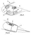
- four lugs can be placed in the spans of the structural beam 3 running between the shells or cases 4, as indicated with reference 8 in figure 9. Two other lugs, one on each side, not shown in the drawing, will be arranged in coincidence with the coinciding spans of the structural beam 3 and the cases 4.
- lugs are not parallel to any of the axes of the end section of the modules, being able to use a system of lugs similar to lugs 6, 8 of figure 1, with the same system for anchoring or attaching to the beams, by means of non-countersunk screws, since they do not affect the aerodynamic surface.
- the two modules 1 and 2 are provided with indentations 16 starting from the edge of the end sections, which define an opening on which the plates 23 and 24 are coupled when said modules are abutted, said plates being provided with a central opening 29, facing in both plates, for the introduction of the attachment screws and coupling nuts.
Abstract
Description
- The present invention refers to a wind turbine blade, transversely subdivided into two or more independent spans provided with connecting means in the faceable end sections.
- Wind turbines are designed to obtain increasingly greater power. Among the components intervening in the wind turbine power are the blades forming the rotor. The aerodynamic features and dimensions of the blades are fundamental for increasing the power of the turbine. For this reason, increasingly longer blades are manufactured.
- Since wind turbines are usually assembled in difficult to access places, transporting the blades is usually very problematic, especially due to their length.
- To resolve the problem set forth, transversely subdividing the blades into two or more independent spans or modules, which are provided with jointing means in the faceable sections, is already known.
- In this sense, European Patent EP 1,244,873 can be cited, which discloses a wind turbine rotor blade transversely subdivided into sections joined to one another by means of a plurality of plates connecting the faceable edges of consecutive sections. The jointing of the plates with the edges of the sections to be connected can be carried out by means of bolts placed on the surfaces of said sections, along their edges. This system has the drawback of the large number of existing connections, taking into account the fact that they must be carried out in the field, with limited means. On the other hand, most of the points of attachment are arranged outside of the resistant inner frame, which reduces the resistance of said points of attachment, requiring for that purpose a large number of points of attachment.
- A wind turbine rotor blade subdivided into at least two segments joined to one another by means of expansion screws is known by German patent DE 3,109,566. The placement of these screws is also difficult, taking into account the conditions in which the assembly operations must be carried out.
- United States patent US 4,389,162 discloses a wind turbine rotor blade transversely subdivided into several sections. The jointing means consists of a longitudinal element with high tensile strength, for example a cable, running inside the different sections of the blade and anchored to anchorings arranged in the end sections. This system has the same aforementioned assembly drawbacks and also requires a special constitution of the different components.
- The object of the present invention is a wind turbine blade made up of an internal longitudinal reinforcement structure and of external aerodynamic shells or cases joined to the structure, the blade being transversely subdivided into two or more sections or modules fixed to one another by means of a reduced number of easy to carry out connections, which facilitates assembly of the blades in the field because of the features of the joints and the reduced number thereof, allowing the interchangeability of modules.
- Transportation to the wind turbine assembly site is facilitated by means of the subdivision of the blades into modules of a determined length.
- On the other hand, assembly times are reduced since the number of joints is reduced and since these are constituted such that they can be easily carried out in the field. All this makes it possible not only to solve logistic problems with the present invention, but also to allow meeting the objective of logistic optimization.
- The internal longitudinal reinforcement structure can be made up of a structural box beam and external aerodynamic cases or shells joined to two of the opposing walls of the structural beam, both being made up of resins reinforced with fibers of a different nature. The blade, made up of the beam and shells, is transversely subdivided into modules provided with connecting means on their facing edges.
- According to the invention, the connecting means are arranged in coincidence with the end sections of the internal longitudinal reinforcement structure and are constituted of lugs axially projecting from the edges of said end sections in coinciding positions, such that when consecutive modules are coupled, the lugs thereof are abutted or facing one another in order to receive jointing elements.
- The lugs are preferably provided with an end hole which, in the event that the lugs are abutted when the modules are coupled, said holes are aligned in each pair of abutted lugs to receive an attachment screw or jointing rivet. When the lugs are facing each other, without abutting, intermediate plates provided with holes which can be aligned with those of said lugs are arranged on each pair of facing lugs for the introduction of attachment screws or jointing rivets.
- The modules forming the blade have, starting from the free edge and preferably in the area where the connecting means will be arranged, indentations defining an access opening through which the attachment screws or jointing rivets are arranged and/or handled when two consecutive modules are coupled. This opening can be made in the cases, near the free edge of the modules, to access the assembly of the attaching screws.
- The main features of the jointing described is the interchangeability and easy field assembly, qualities which can exist only when there are few points of attachment.
- In this sense, the lugs can be arranged parallel to either of the axes of the end sections, in which case the connecting means can be constituted of a maximum of six lugs, fixed in spans in which the internal longitudinal reinforcement structure and the shells or cases coincide and are joined, and in spans of said structure running between the shells or cases. The existence of lugs in each span allows absorbing all the components of the joint loads.
- As an alternative, the lugs can be arranged in a position not parallel to either of the axes of the end sections, in which case it could be sufficient to arrange four lugs, by means of which all the components of the joint loads could also be absorbed.
- In either case, since the internal longitudinal reinforcement structure is the main element responsible for the structural integrity of the blade, the jointing elements must be arranged such that they provide continuity to the reinforcement structure of each one of the modules to connect.
- The jointing between the lugs and the modules can be carried out by means of screws. These joints are carried out in the manufacturing plants, the module therefore being constituted of the blade section and the different assembled lugs. The jointing between both modules would subsequently be carried out in the field by means of the through screws or bolts constituting the jointing elements.
- Finally, the aerodynamic surface is closed, between consecutive modules, with a non-structural, or rather a structurally secondary, cuff. The joining of said cuff to the modules is screwed down. To this end, a flat bar containing the coupling nuts is assembled in each one of the modules, starting from the end sections and on their internal surface, in the manufacturing plant. Thus, when the jointing is carried out in the field, the operator will only have to position the cuff and introduce the screws from the outside, without needing to hold the nuts.
- The features and advantages of the invention will be better understood with the following description, made in reference to the attached drawings which show a nonlimiting embodiment.
- In the drawings:
- Figure 1 shows a perspective view of the connectable ends of the modules, provided with connecting means constituted according to the invention.
- Figure 2 shows an upper plan view of the modules of figure 1, once joined and with the cuff closing the aerodynamic surface thereof.
- Figure 3 shows a cross-sectional view of a joint between consecutive modules, taken along section line III-III of figure 2.
- Figure 4 shows a longitudinal sectional view of the cuff closing the aerodynamic surface, taken along section line IV-IV of figure 2.
- Figure 5 shows a longitudinal sectional view of one of the lugs forming part of the connecting means of the invention.
- Figure 6 shows a view similar to figure 1, showing an embodiment variant.
- Figure 7 shows a view similar to figure 2, corresponding to the embodiment variant of figure 6.
- Figure 8 shows a view similar to figure 3, but taken along VIII-VIII section line of figure 7.
- Figure 9 shows a schematic perspective view of the end section of one of the modules, with a different lug arrangement than that shown in figure 1.
- Figure 10 shows a view similar to figure 9, showing an embodiment variant in the arrangement of the lugs.
-
- In wind turbine blades transversely subdivided into modules, the first question posed is how many modules the blade should be divided into, according to different factors, among which the manufacturing means, the transportation possibilities, etc., can be considered. The blades can be subdivided, for example, into three modules, although a subdivision into a larger number of modules of a smaller length, or a smaller number of modules of a longer length, could be decided according to other factors.
- Figure 1 shows a perspective view of the faceable end sections of two
consecutive modules 1 and 2 of a wind turbine blade. These blades are mainly made up of an internal reinforcement structure, in the form of a structural beam 3 in the example described, and of aerodynamic shells orcases 4 joined to the beam 3, either one being able to be made up of resins reinforced with fibers of a different nature. - The end sections are provided with connecting means constituted of lugs fixed to each span or
module 1 and 2 and projecting axially therefrom, indicated withnumbers 5 and 6 in module 1 and withnumbers module 2, all the lugs being arranged in coincidence with the end sections of the structural beam 3, each of the lugs in both modules being arranged in coinciding positions. - In the case shown in figure 1, the connecting means are made up of six lugs, four of which, indicated with
numbers 5 and 7, are fixed in spans of the structural beam 3 coinciding with the shells orcases 4, two placed on each side following the trajectory of said spans, whereas the other two lugs, indicated withnumbers case 4, as an extension of said spans. - All the lugs are provided with a
hole 9 in the portion projecting from the edge of the modules. Furthermore, the lugs have such a length that when abutted against one another, the end sections of themodules 1 and 2 partially overlap, such that theholes 9 of abutted lugs are aligned to receive an attachment screw orbolt 10, figure 3. - As can be seen in figure 3, the
lugs 7 split in the end portion into two branches 11 between which the lug 5 of the opposing module 1 is introduced, theholes 9 of the branches being aligned with thehole 9 of the lugs 5 for the passage of the connecting screw orbolt 10. - As can be seen in figure 1, the
lugs 5 and 7 have an approximately rectangular contour and are abutted at the internal surface of the structural beam, being fixed to the wall of said beam andshells 4 by means ofcountersunk head screws 12, figure 3, to prevent them from projecting from the aerodynamic surface, which fixing is carried out in the factory. - The
lugs 6 are flat and double, each one fixed at one of the surfaces of the corresponding walls of the structural beam, also by means of screws. With regard to thelugs 8, as is shown in figure 5, which is a longitudinal sectional view of one of these lugs, they are provided with an intermediatetransverse bend 13 and are abutted against and fixed to the corresponding wall of the structural beam atspan 14, by means of screws, the end span 15 of each pair of lugs abutted against one another running to be introduced between the opposing pair of lugs, theholes 9 of each of the lugs facing one another to introduce the attachment screws or bolts. - In the example shown in figure 1, one of the modules, the one indicated with
number 2, is provided with anindentation 16 starting from the free edge which defines an opening through which the screws or nuts making up the jointing elements between the different lugs can be introduced when themodules 1 and 2 are coupled together. The opening for accessing the jointing elements could be located on the case, near the free edge of the module. Furthermore, the two modules can have a peripheral stepping 17 starting from the free end sections, which defines a peripheral seating when said modules are coupled where a strip closing the aerodynamic surface and defining a structurally secondary cuff is arranged. The jointing of thiscuff 18 to the modules is carried out by means of countersunkscrews 19, figures 2 and 4, to which end aflat bar 20 containing thecoupling nuts 21 is assembled in each one of the modules at the internal surface thereof and starting from its free edge. Thus, when the jointing is carried out in the field, the operator must simply position thecuff 18 and introduce thescrews 19 from the outside, without needing to hold the nuts 21. - In the embodiment shown in figure 6, the
lugs 5 and 7 have a shorter length, such that when themodules 1 and 2 are abutted, said lugs do not overlap, theholes 9 of facing lugs being spaced a certain distance from one another. In this case, the jointing is carried out by means ofintermediate plates plates holes holes 9 of thelugs 5 and 7, respectively, to receive the attachment screws or bolts 10', as can be seen in figures 7 and 8. This system will allow reducing the cost of thefemale lugs 7 of figure 1, which is a high cost because it is manufactured by machining. In the embodiment of figure 6, there are no male and female lugs, since thelugs 5 and 7 have an equal configuration. As indicated, the jointing between theintermediate plates - Otherwise, the embodiment of figure 6, with regard to the fixing of the
lugs strip 18 forming the cuff, coincide with that described in relation to figure 1. - If it is desired to prevent joints close to the aerodynamic surface, four lugs can be placed in the spans of the structural beam 3 running between the shells or
cases 4, as indicated withreference 8 in figure 9. Two other lugs, one on each side, not shown in the drawing, will be arranged in coincidence with the coinciding spans of the structural beam 3 and thecases 4. - In the case of figures 1 and 6, as well as in the case of figure 9, it is necessary to arrange lugs in the spans of the structural beam 3 coinciding with the
cases 4, as well as in the spans of the structural beam 3 running between said cases, due to the parallelism between lugs, incapable of absorbing all the components of the joint loads. However, by slightly modifying the geometry of the beam 3 such that thelugs 8 are not parallel, the jointing system can be resolved with just four points which are shown in figure 10. In this case, only fourlugs 28 are arranged, only one of which is shown in the drawing. These four lugs are not parallel to any of the axes of the end section of the modules, being able to use a system of lugs similar tolugs - In the embodiment of figure 6, the two
modules 1 and 2 are provided withindentations 16 starting from the edge of the end sections, which define an opening on which theplates central opening 29, facing in both plates, for the introduction of the attachment screws and coupling nuts.
Claims (7)
- A wind turbine blade, transversely subdivided into two or more independent modules (1-2) provided on their end sections with connecting means, which modules comprise external aerodynamic walls or cases (4) and an internal longitudinal reinforcement structure (3), characterized in that said connecting means are arranged in coincidence with the end sections of the internal longitudinal reinforcement structure (3) and are constituted of lugs (5-7, 6-8) which are fixed to each module and axially project from the end sections of said modules in coinciding positions, which lugs are each provided with at least one hole (9) for receiving jointing elements between facing lugs.
- A blade according to claim 1, characterized in that the shells or cases and the internal longitudinal reinforcement structure are provided with faceable indentations (16) starting from the free edge, in coinciding spans, which define access openings through which the jointing elements between facing lugs are arranged when consecutive modules are abutted.
- A blade according to claim 1, characterized in that the faceable edges of consecutive modules have an external peripheral indentation (16) on the wall or case which defines a peripheral seating when said modules are abutted and joined, in which a strip or cuff (18) is arranged closing the aerodynamic surface and fixed to the bottom of both indentations by means of screws (19).
- A blade according to claim 3, characterized in that said modules are provided with a flat bar (20) fixed on its internal surface, starting from the sections or end sections, which flat bar bears nuts (21) for screwing in the attaching screws (19) for fixing the strip or cuff.
- A blade according to claim 1, characterized in that the lugs (5-7, 6-8) of faceable sections of consecutive modules are arranged such that when said spans are abutted, the facing lugs are abutted, with the holes (9) being aligned, and the jointing means consist of an attachment screw or bolt (10) which can be introduced through said aligned holes.
- A blade according to claim 1, characterized in that the lugs (5-7) of adjacent sections of consecutive modules placed in coincidence with the shell or case do not project from the edge of said shell and are arranged such that the facing lugs are located on a single plane, with the holes (9) being spaced a certain distance from one another, the jointing means being constituted of intermediate plates (23-24) which are placed on each pair of facing lugs (5) and are provided with holes (26-27) which can be aligned with those of said lugs to receive attachment screws or bolts (10').
- A blade according to claim 1, characterized in that the lugs are abutted against the internal surface of the modules, starting from the free edge or edges thereof, and are joined to said modules by means of screws (12).
Priority Applications (4)
| Application Number | Priority Date | Filing Date | Title |
|---|---|---|---|
| EP04380080A EP1584817A1 (en) | 2004-04-07 | 2004-04-07 | Wind turbine blade |
| CN200580016547XA CN1957178B (en) | 2004-04-07 | 2005-03-31 | Wind turbine blade |
| US11/547,745 US7901188B2 (en) | 2004-04-07 | 2005-03-31 | Wind turbine blade |
| PCT/ES2005/000168 WO2005100781A1 (en) | 2004-04-07 | 2005-03-31 | Wind turbine blade |
Applications Claiming Priority (1)
| Application Number | Priority Date | Filing Date | Title |
|---|---|---|---|
| EP04380080A EP1584817A1 (en) | 2004-04-07 | 2004-04-07 | Wind turbine blade |
Publications (1)
| Publication Number | Publication Date |
|---|---|
| EP1584817A1 true EP1584817A1 (en) | 2005-10-12 |
Family
ID=34896170
Family Applications (1)
| Application Number | Title | Priority Date | Filing Date |
|---|---|---|---|
| EP04380080A Withdrawn EP1584817A1 (en) | 2004-04-07 | 2004-04-07 | Wind turbine blade |
Country Status (4)
| Country | Link |
|---|---|
| US (1) | US7901188B2 (en) |
| EP (1) | EP1584817A1 (en) |
| CN (1) | CN1957178B (en) |
| WO (1) | WO2005100781A1 (en) |
Cited By (51)
| Publication number | Priority date | Publication date | Assignee | Title |
|---|---|---|---|---|
| WO2006103307A3 (en) * | 2005-03-31 | 2006-11-30 | Gamesa Corporacion Technologic | Blade for wind-power generators |
| WO2008084126A1 (en) * | 2007-01-08 | 2008-07-17 | Guillermo Petri Larrea | Reversible system for sectioning wind generator blades in several parts |
| EP1965074A2 (en) | 2007-02-28 | 2008-09-03 | Gamesa Innovation And Technology, S.L. | A wind turbine multi-panel blade |
| WO2008071195A3 (en) * | 2006-12-15 | 2008-11-20 | Univ Denmark Tech Dtu | Reinforced aerodynamic profile |
| US7517198B2 (en) | 2006-03-20 | 2009-04-14 | Modular Wind Energy, Inc. | Lightweight composite truss wind turbine blade |
| WO2009090537A2 (en) | 2008-01-14 | 2009-07-23 | Clipper Windpower Technology, Inc. | A modular rotor blade for a power-generating turbine and a method for assembling a power-generating turbine with modular rotor blades |
| EP2157315A1 (en) | 2008-08-21 | 2010-02-24 | Lm Glasfiber A/S | Blade section for a wind turbine blade |
| WO2010026903A1 (en) * | 2008-09-04 | 2010-03-11 | 三菱重工業株式会社 | Wind wheel blade |
| ES2337645A1 (en) * | 2007-09-14 | 2010-04-27 | GAMESA INNOVATION & TECHNOLOGY, S.L. | Flange joint for blade sections of a wind turbine with load sensor on the bolts |
| WO2010046287A2 (en) * | 2008-10-23 | 2010-04-29 | Astrium Sas | Windmill blades and method for production thereof |
| WO2009135902A3 (en) * | 2008-05-07 | 2010-06-10 | Vestas Wind Systems A/S | A sectional blade |
| ES2342998A1 (en) * | 2009-01-19 | 2010-07-20 | Manuel Torres Martinez | Wind turbine blade |
| ES2343712A1 (en) * | 2007-05-03 | 2010-08-06 | Manuel Torres Martinez | Divided wind turbine on tramos and manufacturing process of the same (Machine-translation by Google Translate, not legally binding) |
| WO2009130467A3 (en) * | 2008-04-24 | 2010-09-23 | Blade Dynamics Limited | A wind turbine blade |
| WO2010118517A1 (en) * | 2009-04-13 | 2010-10-21 | 1066626 Ontario Ltd. | Wind turbine blade and method of constructing same |
| EP2243955A2 (en) | 2009-04-22 | 2010-10-27 | Gamesa Innovation & Technology, S.L. | Lightning protection system for sectional wind turbine blades |
| WO2011006805A2 (en) | 2009-07-16 | 2011-01-20 | Astrium Sas | Method for creating mechanical links |
| WO2011006800A1 (en) | 2009-07-16 | 2011-01-20 | Astrium Sas | Device for assembling sections of wind-turbine blades and method for linking sections of wind-turbine blades |
| US7891947B2 (en) | 2008-12-12 | 2011-02-22 | General Electric Company | Turbine blade and method of fabricating the same |
| US20110123343A1 (en) * | 2009-11-24 | 2011-05-26 | Ronner David E | Wind turbine blade and methods, apparatus and materials for fabrication in the field |
| WO2011070137A1 (en) * | 2009-12-11 | 2011-06-16 | Vestas Wind Systems A/S | A sectional blade |
| EP2357357A2 (en) * | 2009-10-01 | 2011-08-17 | Vestas Wind Systems A/S | Wind turbine blade |
| ES2364258A1 (en) * | 2008-03-05 | 2011-08-30 | Manuel Torres Martinez | System for connecting wind generator blade sections |
| EP2418072A1 (en) | 2010-08-13 | 2012-02-15 | Lm Glasfiber A/S | A method of manufacturing an elongated composite structure |
| US8172493B2 (en) | 2009-05-04 | 2012-05-08 | General Electric Company | Apparatus and method for transporting and aligning wind turbine rotor blade |
| ES2385726A1 (en) * | 2012-05-10 | 2012-07-31 | Manuel Torres Martínez | Wind turbine blade formed by sections (Machine-translation by Google Translate, not legally binding) |
| WO2012156547A1 (en) * | 2011-05-13 | 2012-11-22 | Investigaciones Y Desarrollos Eolicos, S.L. | System for joining component portions of wind‑turbine blades |
| WO2013041498A1 (en) | 2011-09-20 | 2013-03-28 | Astrium Sas | Device for the connection of sections of wings and assembly method of such sections |
| US8425195B2 (en) | 2007-09-11 | 2013-04-23 | Blade Dynamics Limited | Wind turbine blade |
| US8485786B2 (en) | 2007-01-16 | 2013-07-16 | Bladena Aps | Reinforced blade for wind turbine |
| US8510947B2 (en) | 2008-11-14 | 2013-08-20 | General Electric Company | Turbine blade fabrication |
| US8632312B2 (en) | 2007-01-25 | 2014-01-21 | Bladena Aps | Reinforced blade for wind turbine |
| DE102012111219A1 (en) | 2012-11-21 | 2014-05-22 | Spitzner Engineers GmbH | Wind turbine component |
| CN103895856A (en) * | 2014-04-24 | 2014-07-02 | 哈尔滨工业大学 | Composite-material I beam connecting device of aerofoils and aeroplane body |
| US8807953B2 (en) | 2008-06-24 | 2014-08-19 | Bladena Aps | Reinforced wind turbine blade |
| DK177938B1 (en) * | 2007-12-19 | 2015-01-19 | Gen Electric | MULTI-SEGMENT WINDOWS AND THEIR COLLECTION PROCEDURE |
| DK178051B1 (en) * | 2007-12-21 | 2015-04-13 | Gen Electric | STRUCTURE AND PROCEDURE FOR SELF-EQUIPMENT-ROTOR SWING COLLECTIONS |
| EP1950414B1 (en) | 2007-01-23 | 2015-09-23 | Hitachi, Ltd. | Separable blade for wind turbine |
| US9255566B2 (en) | 2010-02-10 | 2016-02-09 | Vestas Wind Systems A/S | Sectional blade |
| CN105545612A (en) * | 2016-03-09 | 2016-05-04 | 太原重工股份有限公司 | Large wind power generation unit and blade installation structure thereof |
| US9388789B2 (en) | 2009-12-02 | 2016-07-12 | Vestas Wind Systems A/S | Sectional wind turbine blade |
| US9416768B2 (en) | 2009-12-02 | 2016-08-16 | Bladena Aps | Reinforced airfoil shaped body |
| US9500179B2 (en) | 2010-05-24 | 2016-11-22 | Vestas Wind Systems A/S | Segmented wind turbine blades with truss connection regions, and associated systems and methods |
| US9518558B2 (en) | 2008-12-05 | 2016-12-13 | Vestas Wind Systems A/S | Efficient wind turbine blades, wind turbine blade structures, and associated systems and methods of manufacture, assembly and use |
| US9806581B2 (en) | 2010-06-25 | 2017-10-31 | Fisher & Paykel Appliances Limited | Rotor for a motor, and a motor and an appliance comprising the rotor, and a method for making a rotor |
| EP3248863A1 (en) * | 2016-05-24 | 2017-11-29 | Airbus Operations Limited | Winglet |
| WO2018121826A1 (en) * | 2016-12-28 | 2018-07-05 | Vestas Wind Systems A/S | Connection joint for a sectional wind turbine rotor blade and associated methods |
| WO2019219139A1 (en) * | 2018-05-16 | 2019-11-21 | Vestas Wind Systems A/S | Connection joint for a sectional wind turbine blade and associated methods |
| EP3581790A1 (en) * | 2018-06-14 | 2019-12-18 | Siemens Gamesa Renewable Energy A/S | Wind turbine rotor blade |
| US11506182B2 (en) | 2018-04-23 | 2022-11-22 | Vestas Wind Systems A/S | Wind turbine blade assembly |
| US20230020641A1 (en) * | 2019-12-23 | 2023-01-19 | Vestas Wind Systems A/S | Modular wind turbine blade with vibration damping |
Families Citing this family (57)
| Publication number | Priority date | Publication date | Assignee | Title |
|---|---|---|---|---|
| WO2008092451A2 (en) * | 2007-01-29 | 2008-08-07 | Danmarks Tekniske Universitet | Wind turbine blade |
| ES2333499B1 (en) * | 2007-09-11 | 2010-10-15 | Manuel Torres Martinez | SHOVEL FOR AEROGENERATOR. |
| ES2352945B2 (en) * | 2007-11-23 | 2011-10-19 | Investigaciones Y Desarrollos Eolicos, S.L. | MOUNTING SYSTEM FOR THE UNION OF FLAGS OF AEROGENERATOR BLADES. |
| US7740453B2 (en) * | 2007-12-19 | 2010-06-22 | General Electric Company | Multi-segment wind turbine blade and method for assembling the same |
| US8231351B2 (en) * | 2007-12-27 | 2012-07-31 | General Electric Company | Adaptive rotor blade for a wind turbine |
| WO2009155921A1 (en) * | 2008-06-23 | 2009-12-30 | Danmarks Tekniske Universitet | A wind turbine blade with angled girders |
| ES2385516B1 (en) * | 2008-06-27 | 2013-05-31 | Gamesa Innovation & Technology, S.L. | INSERT OF SHOVEL AND METHOD OF PLACEMENT OF THE SAME. |
| WO2010023299A2 (en) * | 2008-08-31 | 2010-03-04 | Vestas Wind Systems A/S | A sectional blade |
| EP2391807B1 (en) * | 2009-01-27 | 2015-04-22 | Vestas Wind Systems A/S | A sectional wind turbine blade |
| CN101718250B (en) * | 2010-01-11 | 2011-11-09 | 华锐风电科技(集团)股份有限公司 | Sectional type wind wheel vanes of wind power generator set and assembly method thereof |
| CN103038500B (en) * | 2010-05-24 | 2016-11-23 | 维斯塔斯风力系统有限公司 | There is the segmentation wind turbine blade of truss join domain, and related system and method |
| US8172539B2 (en) | 2010-06-17 | 2012-05-08 | General Electric Company | Wind turbine rotor blade joint |
| US7997874B2 (en) * | 2010-08-19 | 2011-08-16 | General Electric Company | Wind turbine rotor blade joint |
| DE102010040596A1 (en) * | 2010-09-10 | 2012-03-15 | Aloys Wobben | Removable rotor blade tip |
| GB2484107A (en) | 2010-09-29 | 2012-04-04 | Nenuphar | Modular wind turbine blade for a vertical axis wind turbine |
| JP4939640B2 (en) * | 2010-10-22 | 2012-05-30 | 三菱重工業株式会社 | Wind turbine rotor |
| ES2398553B1 (en) | 2011-02-24 | 2014-02-06 | Gamesa Innovation & Technology S.L. | A MULTI-PANEL IMPROVED AIRPLANE SHOVEL. |
| ES2399259B1 (en) | 2011-05-24 | 2014-02-28 | Gamesa Innovation & Technology, S.L. | A joining method for a multi-panel wind turbine blade. |
| CN102278275A (en) * | 2011-07-04 | 2011-12-14 | 唐山市拓又达科技有限公司 | Fan blade of large vertical axis wind turbine and manufacturing method |
| ES2401511B1 (en) | 2011-07-06 | 2014-04-14 | Gamesa Innovation & Technology S.L. | Method of manufacturing variable length wind turbine blades. |
| US20120141287A1 (en) * | 2011-08-29 | 2012-06-07 | General Electric Company | Wind turbine rotor blade joint |
| CN102297077B (en) * | 2011-09-23 | 2013-04-17 | 清华大学 | Modularized large wind turbine blade structure capable of being inflated and exhausted |
| US8918997B2 (en) | 2011-10-13 | 2014-12-30 | General Electric Company | Method for assembling a multi-segment wind turbine rotor blade with span-wise offset joints |
| US8517689B2 (en) | 2011-10-13 | 2013-08-27 | General Electric Company | Multi-segment wind turbine rotor blade with span-wise offset joints |
| CN102518568B (en) * | 2011-12-27 | 2014-02-12 | 东方电气集团东方汽轮机有限公司 | Wind power sectional-type blade |
| ES2425026B1 (en) | 2012-04-03 | 2014-12-05 | Gamesa Innovation & Technology, S.L. | Method of manufacturing a component of a split blade of a wind turbine |
| US11261735B2 (en) * | 2013-03-07 | 2022-03-01 | Textron Innovations Inc. | Removable rotor blade tip |
| US9470205B2 (en) | 2013-03-13 | 2016-10-18 | Vestas Wind Systems A/S | Wind turbine blades with layered, multi-component spars, and associated systems and methods |
| US9297357B2 (en) | 2013-04-04 | 2016-03-29 | General Electric Company | Blade insert for a wind turbine rotor blade |
| US9394881B2 (en) * | 2013-05-29 | 2016-07-19 | Siemens Aktiengesellschaft | Wind turbine blade and method of fabricating a wind turbine blade |
| US9739259B2 (en) | 2013-06-05 | 2017-08-22 | The Regents Of The University Of California | Wind turbine blade with biplane section |
| US9506452B2 (en) | 2013-08-28 | 2016-11-29 | General Electric Company | Method for installing a shear web insert within a segmented rotor blade assembly |
| US9605651B2 (en) | 2013-12-04 | 2017-03-28 | General Electric Company | Spar assembly for a wind turbine rotor blade |
| US9790919B2 (en) * | 2014-02-25 | 2017-10-17 | General Electric Company | Joint assembly for rotor blade segments of a wind turbine |
| EP3106656B1 (en) * | 2015-06-19 | 2018-11-14 | GE Renewable Technologies Wind B.V. | Wind turbine blade modules and wind turbine blades |
| DE102015120113A1 (en) * | 2015-11-20 | 2017-05-24 | Wobben Properties Gmbh | Wind turbine rotor blade and wind turbine |
| DK3563052T3 (en) * | 2016-12-28 | 2021-04-26 | Vestas Wind Sys As | LED TO CONNECT A WIND TURBINE ROTOR WING TO A ROTOR HUB AND ASSOCIATED PROCEDURES |
| US10495058B2 (en) * | 2017-02-21 | 2019-12-03 | General Electric Company | Joint assembly for rotor blade segments of a wind turbine |
| US10563636B2 (en) | 2017-08-07 | 2020-02-18 | General Electric Company | Joint assembly for a wind turbine rotor blade |
| CN108087191B (en) * | 2017-12-25 | 2020-01-31 | 江苏金风科技有限公司 | Sectional blade, method for connecting sectional blades and wind generating set |
| US10830207B2 (en) | 2018-08-28 | 2020-11-10 | General Electric Company | Spar configuration for jointed wind turbine rotor blades |
| BR112021006655A2 (en) | 2018-10-25 | 2021-07-13 | General Electric Company | jointed wind turbine rotor blade and wind turbine |
| EP3874155B1 (en) | 2018-10-31 | 2023-07-19 | General Electric Company | Jointed wind turbine rotor blade having varying material combinations along its span for pin reinforcement |
| US11486352B2 (en) | 2018-11-01 | 2022-11-01 | General Electric Company | Scarf connection for a wind turbine rotor blade |
| CN112912615A (en) | 2018-11-01 | 2021-06-04 | 通用电气公司 | Wind turbine engaged rotor blade with hollow chordwise extending pin |
| CN112912614A (en) | 2018-11-01 | 2021-06-04 | 通用电气公司 | Method for mounting and retaining a bushing in a carrier block of a rotor blade joint |
| JP7210723B2 (en) | 2018-11-01 | 2023-01-23 | ゼネラル・エレクトリック・カンパニイ | Spacer material for reducing coupling gap between segmented rotor blade beam structure and blade shell |
| US11828264B2 (en) | 2018-11-01 | 2023-11-28 | General Electric Company | Compliant structures for jointed rotor blades |
| WO2020091792A1 (en) | 2018-11-01 | 2020-05-07 | General Electric Company | Span-wise extending pin for joining rotor blade segments |
| CN113167211A (en) | 2018-12-11 | 2021-07-23 | 通用电气公司 | Beam structure for a segmented rotor blade with transition shape |
| JP7297897B2 (en) | 2018-12-11 | 2023-06-26 | ゼネラル・エレクトリック・カンパニイ | Method for manufacturing blade segment structural components for wind turbine rotor blades |
| WO2020122865A1 (en) | 2018-12-11 | 2020-06-18 | General Electric Company | Method for manufacturing a structural component of a blade segment for a rotor blade of a wind turbine |
| EP3894194A1 (en) | 2018-12-11 | 2021-10-20 | General Electric Company | Method for manufacturing a hollow composite structure, particularly a spar beam for a wind turbine rotor blade, and an associated mandrel |
| US11614069B2 (en) | 2018-12-13 | 2023-03-28 | General Electric Company | Jointed rotor blade having a chord-wise extending pin supported via one or more structural members |
| WO2020131043A1 (en) | 2018-12-19 | 2020-06-25 | General Electric Company | Jointed rotor blade having internal support structure with varying fiber orientation for pin reinforcement |
| CN113167214A (en) | 2018-12-20 | 2021-07-23 | 通用电气公司 | Joint wind turbine rotor blade with spar caps constructed of different forms of material along its span |
| US20220178346A1 (en) * | 2019-03-01 | 2022-06-09 | General Electric Company | Jointed wind turbine rotor blade with chord-wise extending pin bushings designed to minimize chord-wise gap |
Citations (7)
| Publication number | Priority date | Publication date | Assignee | Title |
|---|---|---|---|---|
| FR1070262A (en) * | 1952-02-02 | 1954-07-21 | Chantiers De France Atel | Hollow rotor blade with variable pitch, especially for wind motor rotors |
| GB818403A (en) * | 1955-10-31 | 1959-08-19 | Aerotecnica S A | Rotor blades for rotary wing aircraft |
| FR1187166A (en) * | 1957-11-14 | 1959-09-08 | Improvements made to blade machines, particularly wind turbines | |
| US4295790A (en) * | 1979-06-21 | 1981-10-20 | The Budd Company | Blade structure for use in a windmill |
| DE19962989A1 (en) * | 1999-12-24 | 2001-07-05 | Aloys Wobben | Butt joint for hollow profiles |
| EP1184566A1 (en) * | 1999-05-31 | 2002-03-06 | Manuel Torres Martinez | Aerogenerator blade |
| DE10235496A1 (en) * | 2002-08-02 | 2004-02-12 | Ge Wind Energy Gmbh | Method for making wind turbine blade comprises fitting connectors over joint between two sections of blade, gap between inner surfaces of connector and blade sections then being filled with resin |
Family Cites Families (2)
| Publication number | Priority date | Publication date | Assignee | Title |
|---|---|---|---|---|
| NL8602097A (en) * | 1986-08-18 | 1988-03-16 | Strijense Kunststof Technieken | WIND TURBINE ROTOR WITH TWO ROTOR BLADES. |
| JP2004011616A (en) | 2002-06-11 | 2004-01-15 | Shin Meiwa Ind Co Ltd | Wind mill blade structure for wind power generator |
-
2004
- 2004-04-07 EP EP04380080A patent/EP1584817A1/en not_active Withdrawn
-
2005
- 2005-03-31 WO PCT/ES2005/000168 patent/WO2005100781A1/en active Application Filing
- 2005-03-31 US US11/547,745 patent/US7901188B2/en not_active Expired - Fee Related
- 2005-03-31 CN CN200580016547XA patent/CN1957178B/en not_active Expired - Fee Related
Patent Citations (7)
| Publication number | Priority date | Publication date | Assignee | Title |
|---|---|---|---|---|
| FR1070262A (en) * | 1952-02-02 | 1954-07-21 | Chantiers De France Atel | Hollow rotor blade with variable pitch, especially for wind motor rotors |
| GB818403A (en) * | 1955-10-31 | 1959-08-19 | Aerotecnica S A | Rotor blades for rotary wing aircraft |
| FR1187166A (en) * | 1957-11-14 | 1959-09-08 | Improvements made to blade machines, particularly wind turbines | |
| US4295790A (en) * | 1979-06-21 | 1981-10-20 | The Budd Company | Blade structure for use in a windmill |
| EP1184566A1 (en) * | 1999-05-31 | 2002-03-06 | Manuel Torres Martinez | Aerogenerator blade |
| DE19962989A1 (en) * | 1999-12-24 | 2001-07-05 | Aloys Wobben | Butt joint for hollow profiles |
| DE10235496A1 (en) * | 2002-08-02 | 2004-02-12 | Ge Wind Energy Gmbh | Method for making wind turbine blade comprises fitting connectors over joint between two sections of blade, gap between inner surfaces of connector and blade sections then being filled with resin |
Cited By (93)
| Publication number | Priority date | Publication date | Assignee | Title |
|---|---|---|---|---|
| WO2006103307A3 (en) * | 2005-03-31 | 2006-11-30 | Gamesa Corporacion Technologic | Blade for wind-power generators |
| EP1878915A2 (en) * | 2005-03-31 | 2008-01-16 | Gamesa Innovation & Technology, S.L. | Blade for wind-power generators |
| EP1878915A4 (en) * | 2005-03-31 | 2012-12-05 | Gamesa Innovation & Tech Sl | Blade for wind-power generators |
| US8511996B2 (en) | 2005-03-31 | 2013-08-20 | Gamesa Innovation & Technology, S.L. | Blade for wind-power generator formed by attaching multiple independent sections utilizing connection means at the end of each opposing sections |
| US7891950B2 (en) | 2006-03-20 | 2011-02-22 | Modular Wind Energy, Inc. | Lightweight composite truss wind turbine blade |
| US7517198B2 (en) | 2006-03-20 | 2009-04-14 | Modular Wind Energy, Inc. | Lightweight composite truss wind turbine blade |
| US7891948B2 (en) | 2006-03-20 | 2011-02-22 | Modular Wind Energy, Inc. | Lightweight composite truss wind turbine blade |
| US7891949B2 (en) | 2006-03-20 | 2011-02-22 | Modular Wind Energy, Inc. | Lightweight composite truss wind turbine blade |
| US8454318B2 (en) | 2006-12-15 | 2013-06-04 | Bladena Aps | Reinforced aerodynamic profile |
| WO2008071195A3 (en) * | 2006-12-15 | 2008-11-20 | Univ Denmark Tech Dtu | Reinforced aerodynamic profile |
| ES2319599A1 (en) * | 2007-01-08 | 2009-05-08 | Guillermo Petri Larrea | Reversible system for sectioning wind generator blades in several parts |
| US8356982B2 (en) | 2007-01-08 | 2013-01-22 | Guillermo Petri Larrea | Reversible system for dividing aerogenerator blades into several parts |
| WO2008084126A1 (en) * | 2007-01-08 | 2008-07-17 | Guillermo Petri Larrea | Reversible system for sectioning wind generator blades in several parts |
| US8485786B2 (en) | 2007-01-16 | 2013-07-16 | Bladena Aps | Reinforced blade for wind turbine |
| EP1950414B1 (en) | 2007-01-23 | 2015-09-23 | Hitachi, Ltd. | Separable blade for wind turbine |
| US8632312B2 (en) | 2007-01-25 | 2014-01-21 | Bladena Aps | Reinforced blade for wind turbine |
| US8262361B2 (en) | 2007-02-28 | 2012-09-11 | Gamesa Innovation & Technology, S.L. | Wind turbine multi-panel blade |
| EP1965074A2 (en) | 2007-02-28 | 2008-09-03 | Gamesa Innovation And Technology, S.L. | A wind turbine multi-panel blade |
| ES2343712A1 (en) * | 2007-05-03 | 2010-08-06 | Manuel Torres Martinez | Divided wind turbine on tramos and manufacturing process of the same (Machine-translation by Google Translate, not legally binding) |
| US8696317B2 (en) | 2007-09-11 | 2014-04-15 | Blade Dynamics Limited | Wind turbine blade |
| US8425195B2 (en) | 2007-09-11 | 2013-04-23 | Blade Dynamics Limited | Wind turbine blade |
| ES2337645A1 (en) * | 2007-09-14 | 2010-04-27 | GAMESA INNOVATION & TECHNOLOGY, S.L. | Flange joint for blade sections of a wind turbine with load sensor on the bolts |
| DK177938B1 (en) * | 2007-12-19 | 2015-01-19 | Gen Electric | MULTI-SEGMENT WINDOWS AND THEIR COLLECTION PROCEDURE |
| DK178051B1 (en) * | 2007-12-21 | 2015-04-13 | Gen Electric | STRUCTURE AND PROCEDURE FOR SELF-EQUIPMENT-ROTOR SWING COLLECTIONS |
| WO2009090537A3 (en) * | 2008-01-14 | 2010-03-18 | Clipper Windpower, Inc. | A modular rotor blade for a power-generating turbine and a method for assembling a power-generating turbine with modular rotor blades |
| WO2009090537A2 (en) | 2008-01-14 | 2009-07-23 | Clipper Windpower Technology, Inc. | A modular rotor blade for a power-generating turbine and a method for assembling a power-generating turbine with modular rotor blades |
| ES2364258A1 (en) * | 2008-03-05 | 2011-08-30 | Manuel Torres Martinez | System for connecting wind generator blade sections |
| US9133818B2 (en) | 2008-04-24 | 2015-09-15 | Blade Dynamics Limited | Wind turbine blade |
| WO2009130467A3 (en) * | 2008-04-24 | 2010-09-23 | Blade Dynamics Limited | A wind turbine blade |
| US9765756B2 (en) | 2008-05-07 | 2017-09-19 | Vestas Wind Systems A/S | Sectional blade |
| WO2009135902A3 (en) * | 2008-05-07 | 2010-06-10 | Vestas Wind Systems A/S | A sectional blade |
| US9784240B2 (en) | 2008-06-24 | 2017-10-10 | Bladena Solutions Aps | Reinforced wind turbine blade |
| US8807953B2 (en) | 2008-06-24 | 2014-08-19 | Bladena Aps | Reinforced wind turbine blade |
| WO2010020692A3 (en) * | 2008-08-21 | 2010-06-24 | Lm Glasfiber A/S | Blade section for a wind turbine blade |
| CN102197214B (en) * | 2008-08-21 | 2013-07-10 | Lm玻璃纤维制品有限公司 | Blade section for a wind turbine blade |
| EP2157315A1 (en) | 2008-08-21 | 2010-02-24 | Lm Glasfiber A/S | Blade section for a wind turbine blade |
| WO2010020692A2 (en) * | 2008-08-21 | 2010-02-25 | Lm Glasfiber A/S | Blade section for a wind turbine blade |
| US8770940B2 (en) | 2008-08-21 | 2014-07-08 | Lm Glasfiber A/S | Blade section for a wind turbine blade |
| JP2010059884A (en) * | 2008-09-04 | 2010-03-18 | Mitsubishi Heavy Ind Ltd | Wind turbine blade |
| WO2010026903A1 (en) * | 2008-09-04 | 2010-03-11 | 三菱重工業株式会社 | Wind wheel blade |
| WO2010046287A2 (en) * | 2008-10-23 | 2010-04-29 | Astrium Sas | Windmill blades and method for production thereof |
| FR2937687A1 (en) * | 2008-10-23 | 2010-04-30 | Astrium Sas | WINDBREAD BLADES AND METHOD OF MANUFACTURING THE SAME |
| WO2010046287A3 (en) * | 2008-10-23 | 2010-12-16 | Astrium Sas | Windmill blades and method for production thereof |
| US8510947B2 (en) | 2008-11-14 | 2013-08-20 | General Electric Company | Turbine blade fabrication |
| US9845787B2 (en) | 2008-12-05 | 2017-12-19 | Vestas Wind Systems A/S | Efficient wind turbine blades, wind turbine blade structures, and associated systems and methods of manufacture, assembly and use |
| US9518558B2 (en) | 2008-12-05 | 2016-12-13 | Vestas Wind Systems A/S | Efficient wind turbine blades, wind turbine blade structures, and associated systems and methods of manufacture, assembly and use |
| EP2208885A3 (en) * | 2008-12-12 | 2017-11-15 | General Electric Company | Turbine blade and method of fabricating the same |
| US7891947B2 (en) | 2008-12-12 | 2011-02-22 | General Electric Company | Turbine blade and method of fabricating the same |
| WO2010081921A1 (en) * | 2009-01-19 | 2010-07-22 | Torres Martinez M | Wind turbine blade |
| ES2342998A1 (en) * | 2009-01-19 | 2010-07-20 | Manuel Torres Martinez | Wind turbine blade |
| WO2010118517A1 (en) * | 2009-04-13 | 2010-10-21 | 1066626 Ontario Ltd. | Wind turbine blade and method of constructing same |
| US8662853B2 (en) | 2009-04-13 | 2014-03-04 | Maxiflow Manufacturing Inc. | Wind turbine blade and method of constructing same |
| EP2243955A2 (en) | 2009-04-22 | 2010-10-27 | Gamesa Innovation & Technology, S.L. | Lightning protection system for sectional wind turbine blades |
| US8562296B2 (en) | 2009-04-22 | 2013-10-22 | Gamesa Innovation & Technology, S.L. | Lightning protection system for sectional blades |
| US8172493B2 (en) | 2009-05-04 | 2012-05-08 | General Electric Company | Apparatus and method for transporting and aligning wind turbine rotor blade |
| FR2948154A1 (en) * | 2009-07-16 | 2011-01-21 | Astrium Sas | DEVICE FOR ASSEMBLING WINDMILL BLADE RODS AND METHOD FOR CONNECTING WINDMILL BLADE TRUNCONS |
| US9169825B2 (en) | 2009-07-16 | 2015-10-27 | Astrium Sas | Device for assembling sections of wind-turbine blades and method for linking sections of wind-turbine blades |
| WO2011006805A2 (en) | 2009-07-16 | 2011-01-20 | Astrium Sas | Method for creating mechanical links |
| US9129074B2 (en) | 2009-07-16 | 2015-09-08 | Astrium, Sas | Method for making mechanical links |
| WO2011006800A1 (en) | 2009-07-16 | 2011-01-20 | Astrium Sas | Device for assembling sections of wind-turbine blades and method for linking sections of wind-turbine blades |
| EP2357357A2 (en) * | 2009-10-01 | 2011-08-17 | Vestas Wind Systems A/S | Wind turbine blade |
| EP2357357A3 (en) * | 2009-10-01 | 2014-03-19 | Vestas Wind Systems A/S | Wind turbine blade |
| US20110123343A1 (en) * | 2009-11-24 | 2011-05-26 | Ronner David E | Wind turbine blade and methods, apparatus and materials for fabrication in the field |
| US9388789B2 (en) | 2009-12-02 | 2016-07-12 | Vestas Wind Systems A/S | Sectional wind turbine blade |
| US9416768B2 (en) | 2009-12-02 | 2016-08-16 | Bladena Aps | Reinforced airfoil shaped body |
| WO2011070137A1 (en) * | 2009-12-11 | 2011-06-16 | Vestas Wind Systems A/S | A sectional blade |
| US9255566B2 (en) | 2010-02-10 | 2016-02-09 | Vestas Wind Systems A/S | Sectional blade |
| US9500179B2 (en) | 2010-05-24 | 2016-11-22 | Vestas Wind Systems A/S | Segmented wind turbine blades with truss connection regions, and associated systems and methods |
| US9806581B2 (en) | 2010-06-25 | 2017-10-31 | Fisher & Paykel Appliances Limited | Rotor for a motor, and a motor and an appliance comprising the rotor, and a method for making a rotor |
| WO2012019888A1 (en) | 2010-08-13 | 2012-02-16 | Lm Glasfiber A/S | A method of manufacturing an elongated composite structure |
| US9050786B2 (en) | 2010-08-13 | 2015-06-09 | Lm Glasfiber A/S | Method of manufacturing an elongated composite structure |
| EP2418072A1 (en) | 2010-08-13 | 2012-02-15 | Lm Glasfiber A/S | A method of manufacturing an elongated composite structure |
| US9574545B2 (en) | 2011-05-13 | 2017-02-21 | Investigaciones Y Desarrollos Eolicos S.L. | Connection system for connecting component sections of wind turbine blades |
| CN103765004A (en) * | 2011-05-13 | 2014-04-30 | 风力研究及开发有限公司 | System for joining component portions of wind-turbine blades |
| CN103765004B (en) * | 2011-05-13 | 2016-08-24 | 风力研究及开发有限公司 | For connecting the connection system of the member segments of wind turbine blade |
| WO2012156547A1 (en) * | 2011-05-13 | 2012-11-22 | Investigaciones Y Desarrollos Eolicos, S.L. | System for joining component portions of wind‑turbine blades |
| ES2392523A1 (en) * | 2011-05-13 | 2012-12-11 | Investigaciones Y Desarrollos Eólicos, S.L. | System for joining component portions of wind turbine blades |
| WO2013041498A1 (en) | 2011-09-20 | 2013-03-28 | Astrium Sas | Device for the connection of sections of wings and assembly method of such sections |
| ES2385726A1 (en) * | 2012-05-10 | 2012-07-31 | Manuel Torres Martínez | Wind turbine blade formed by sections (Machine-translation by Google Translate, not legally binding) |
| DE102012111219A1 (en) | 2012-11-21 | 2014-05-22 | Spitzner Engineers GmbH | Wind turbine component |
| DE102012111219B4 (en) * | 2012-11-21 | 2016-06-16 | Spitzner Engineers GmbH | Wind turbine component |
| EP2735732A2 (en) | 2012-11-21 | 2014-05-28 | Spitzner Engineers GmbH | Wind energy plant component |
| CN103895856A (en) * | 2014-04-24 | 2014-07-02 | 哈尔滨工业大学 | Composite-material I beam connecting device of aerofoils and aeroplane body |
| CN105545612B (en) * | 2016-03-09 | 2018-02-09 | 太原重工股份有限公司 | Large-scale Wind Turbines and its blade installation structure |
| CN105545612A (en) * | 2016-03-09 | 2016-05-04 | 太原重工股份有限公司 | Large wind power generation unit and blade installation structure thereof |
| EP3248863A1 (en) * | 2016-05-24 | 2017-11-29 | Airbus Operations Limited | Winglet |
| US10597145B2 (en) | 2016-05-24 | 2020-03-24 | Airbus Operations Limited | Winglet |
| WO2018121826A1 (en) * | 2016-12-28 | 2018-07-05 | Vestas Wind Systems A/S | Connection joint for a sectional wind turbine rotor blade and associated methods |
| US11015573B2 (en) | 2016-12-28 | 2021-05-25 | Vestas Wind Systems A/S | Connection joint for a sectional wind turbine rotor blade and associated methods |
| US11506182B2 (en) | 2018-04-23 | 2022-11-22 | Vestas Wind Systems A/S | Wind turbine blade assembly |
| WO2019219139A1 (en) * | 2018-05-16 | 2019-11-21 | Vestas Wind Systems A/S | Connection joint for a sectional wind turbine blade and associated methods |
| EP3581790A1 (en) * | 2018-06-14 | 2019-12-18 | Siemens Gamesa Renewable Energy A/S | Wind turbine rotor blade |
| US20230020641A1 (en) * | 2019-12-23 | 2023-01-19 | Vestas Wind Systems A/S | Modular wind turbine blade with vibration damping |
Also Published As
| Publication number | Publication date |
|---|---|
| WO2005100781A1 (en) | 2005-10-27 |
| CN1957178A (en) | 2007-05-02 |
| US20080145231A1 (en) | 2008-06-19 |
| CN1957178B (en) | 2011-12-07 |
| US7901188B2 (en) | 2011-03-08 |
Similar Documents
| Publication | Publication Date | Title |
|---|---|---|
| US7901188B2 (en) | Wind turbine blade | |
| US8511996B2 (en) | Blade for wind-power generator formed by attaching multiple independent sections utilizing connection means at the end of each opposing sections | |
| CN103459732B (en) | For modular walls and the relevant building of building constructions thing | |
| EP2371706B1 (en) | Torsion box with rib fitting | |
| CN102325990B (en) | Sectional wind turbine blade | |
| CA2787435C (en) | Wind power plant and wind power plant tower segment | |
| EP2317124B1 (en) | Wind turbine blade | |
| US20060083611A1 (en) | Butt connection for hollow profile members | |
| CN102046964A (en) | A sectional blade | |
| TWI509151B (en) | Rear box section, rotor blade with rear box section and wind power installation with such a rotor blade | |
| US5452867A (en) | Shell structural component made of fiber composite material | |
| EP2650534B1 (en) | Nacelle roof structure of wind turbine generator | |
| JP6027096B2 (en) | System for combining components of a wind turbine blade | |
| JP4574442B2 (en) | Horizontal axis windmill blade | |
| US4907382A (en) | Geodesic dome panel assembly and method | |
| WO2021104600A1 (en) | Modular wind turbine blade | |
| JP2019513921A (en) | Partial ring segment connection element and method | |
| US7677496B2 (en) | Stringer for an aircraft wing and a method of reinforcing thereof | |
| EP3568588B1 (en) | Spinner for hub of wind turbine | |
| WO2013084843A1 (en) | Solar cell array, module frame, solar cell module, and joint member | |
| KR100671228B1 (en) | Resin structure | |
| KR20180028221A (en) | Ball-truss having assembly space and truss assembling structure using the ball-truss |
Legal Events
| Date | Code | Title | Description |
|---|---|---|---|
| PUAI | Public reference made under article 153(3) epc to a published international application that has entered the european phase |
Free format text: ORIGINAL CODE: 0009012 |
|
| AK | Designated contracting states |
Kind code of ref document: A1 Designated state(s): AT BE BG CH CY CZ DE DK EE ES FI FR GB GR HU IE IT LI LU MC NL PL PT RO SE SI SK TR |
|
| AX | Request for extension of the european patent |
Extension state: AL HR LT LV MK |
|
| 17P | Request for examination filed |
Effective date: 20060405 |
|
| AKX | Designation fees paid |
Designated state(s): AT BE BG CH CY CZ DE DK EE ES FI FR GB GR HU IE IT LI LU MC NL PL PT RO SE SI SK TR |
|
| 17Q | First examination report despatched |
Effective date: 20060816 |
|
| RAP1 | Party data changed (applicant data changed or rights of an application transferred) |
Owner name: GAMESA INNOVATION & TECHNOLOGY, S.L. UNIPERSONAL |
|
| STAA | Information on the status of an ep patent application or granted ep patent |
Free format text: STATUS: THE APPLICATION IS DEEMED TO BE WITHDRAWN |
|
| 18D | Application deemed to be withdrawn |
Effective date: 20101102 |