EP1500814A1 - Wind turbine rotor blade with wing tip - Google Patents
Wind turbine rotor blade with wing tip Download PDFInfo
- Publication number
- EP1500814A1 EP1500814A1 EP04016618A EP04016618A EP1500814A1 EP 1500814 A1 EP1500814 A1 EP 1500814A1 EP 04016618 A EP04016618 A EP 04016618A EP 04016618 A EP04016618 A EP 04016618A EP 1500814 A1 EP1500814 A1 EP 1500814A1
- Authority
- EP
- European Patent Office
- Prior art keywords
- rotor blade
- rotor
- plane
- wing
- extension
- Prior art date
- Legal status (The legal status is an assumption and is not a legal conclusion. Google has not performed a legal analysis and makes no representation as to the accuracy of the status listed.)
- Ceased
Links
- 230000007704 transition Effects 0.000 claims abstract description 7
- 230000007423 decrease Effects 0.000 claims description 2
- 238000005452 bending Methods 0.000 claims 1
- 230000000750 progressive effect Effects 0.000 abstract 1
- 230000015572 biosynthetic process Effects 0.000 description 1
- 238000005352 clarification Methods 0.000 description 1
- 230000001960 triggered effect Effects 0.000 description 1
- 238000004804 winding Methods 0.000 description 1
Images
Classifications
-
- F—MECHANICAL ENGINEERING; LIGHTING; HEATING; WEAPONS; BLASTING
- F03—MACHINES OR ENGINES FOR LIQUIDS; WIND, SPRING, OR WEIGHT MOTORS; PRODUCING MECHANICAL POWER OR A REACTIVE PROPULSIVE THRUST, NOT OTHERWISE PROVIDED FOR
- F03D—WIND MOTORS
- F03D1/00—Wind motors with rotation axis substantially parallel to the air flow entering the rotor
- F03D1/06—Rotors
- F03D1/0608—Rotors characterised by their aerodynamic shape
- F03D1/0633—Rotors characterised by their aerodynamic shape of the blades
-
- F—MECHANICAL ENGINEERING; LIGHTING; HEATING; WEAPONS; BLASTING
- F05—INDEXING SCHEMES RELATING TO ENGINES OR PUMPS IN VARIOUS SUBCLASSES OF CLASSES F01-F04
- F05B—INDEXING SCHEME RELATING TO WIND, SPRING, WEIGHT, INERTIA OR LIKE MOTORS, TO MACHINES OR ENGINES FOR LIQUIDS COVERED BY SUBCLASSES F03B, F03D AND F03G
- F05B2240/00—Components
- F05B2240/20—Rotors
- F05B2240/30—Characteristics of rotor blades, i.e. of any element transforming dynamic fluid energy to or from rotational energy and being attached to a rotor
- F05B2240/307—Blade tip, e.g. winglets
-
- Y—GENERAL TAGGING OF NEW TECHNOLOGICAL DEVELOPMENTS; GENERAL TAGGING OF CROSS-SECTIONAL TECHNOLOGIES SPANNING OVER SEVERAL SECTIONS OF THE IPC; TECHNICAL SUBJECTS COVERED BY FORMER USPC CROSS-REFERENCE ART COLLECTIONS [XRACs] AND DIGESTS
- Y02—TECHNOLOGIES OR APPLICATIONS FOR MITIGATION OR ADAPTATION AGAINST CLIMATE CHANGE
- Y02E—REDUCTION OF GREENHOUSE GAS [GHG] EMISSIONS, RELATED TO ENERGY GENERATION, TRANSMISSION OR DISTRIBUTION
- Y02E10/00—Energy generation through renewable energy sources
- Y02E10/70—Wind energy
- Y02E10/72—Wind turbines with rotation axis in wind direction
Definitions
- the invention relates to a rotor blade of a rotor of a wind turbine.
- Such rotor blade leaves are preferably to several angularly offset to each other, arranged on a hub. They lead to one Rotary movement for generating electrical energy.
- the rotational movement is caused by Windbeströmung the rotor blades.
- Known Rotor blade leaves can be operated by the Windanströmung generate disturbing noises. Furthermore, they constitute a principle unavoidable flow resistance.
- the invention has for its object to provide a rotor blade, that without loss of performance a reduced flow resistance and preferably also reduced in noise is working.
- the pogelendfortsatz has an aerodynamic cross-sectional profile.
- the winglet also has it a cross-sectional structure that has an aerodynamic profile has.
- the wellgelendfortsatz to the top of the rotor blade is inclined.
- the wing end extension to the bottom of the Rotor wing blade is arranged inclined.
- the angle of inclination is in one area, on the one hand by a non-aligned arrangement characterized by wing extension and adjacent rotor blade is up to an angle of 90 ° between these two Elements.
- the angle can be up to plus 90 ° or up to minus 90 °, depending on whether the rempligelendfortsatz to the top or is arranged inclined to the bottom of the rotor blade.
- the diegelendfortsatz at least over a partial length a smaller chord as the adjacent region of the rotor blade.
- the copegelendfortsatz is narrower or regionally narrower designed as the adjacent rotor blade.
- the rotor end extension to its free end in the measure of its chordal depth decreases, so that the end is tapered so it is not in one punctiform tip must end, but also be flattened can.
- winglets leaking into a punctiform tip are also conceivable.
- the diegelendfortsatz asymmetric is formed to the rotor blade longitudinal axis longitudinal axis.
- the asymmetry can be leading in the direction of rotation or lagging in the direction of rotation That is, the vane end extension is opposite the rotor vane longitudinal center axis staggered.
- a symmetrical design conceivable.
- the transition region of copeendfortsatz and adjacent area of the rotor blade relative to the continuation plane and the wing blade plane arcuate or is formed kink-shaped. With a curved connection there is a curved-continuous transition between the two elements; in the crescent-shaped configuration, the wing plane changes abruptly.
- the rotor blade can with a Vorpfeilung or a rinsepfeilung be provided.
- a Vorpfeilung or a scrubpfeilung be provided.
- the Vorpfeilung or remindpfeilung is in addition to Wing end extension formed.
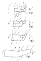
- FIG. 1 shows the free end region 1 of a not completely drawn Rotor wing blade 2.
- the rotor blade 2 rotates through Winding flow around a hub, not shown, which is an axis of rotation 3 has.
- the rotation takes place according to arrow 4 in the drawing plane, that is, from the wind direction 5, clockwise.
- the rotor blade 2 has a wellgelblattend Scheme 6, the extends to a wing end extension 7.
- the wing end extension 7 runs at an angle to the wellgelblattend Scheme 6.
- These two elements abut one another in a transition region 8, wherein This transition region is designed arcuate. Alternatively it is also conceivable that the transition region designed kink-shaped is.
- the blade plane 9 of the diegelblattend Schemes 6 in relation to the extension plane 10 of the copeendfortsatzes 7, it can be seen that these two planes have an angle ⁇ of about Enclose 80 °.
- the wing end extension 7 in the direction of the underside 11 of the rotor blade 2 is angled, this angle can be used as a negative angle, that is, minus 80 °.
- a positive angle ⁇ exists (not shown), that is, the wing end extension 7 is toward the top 12 of the rotor blade 2 angled, he points so in one direction opposite to the wind direction 5.
- the angle ⁇ may preferably be a positive or negative angle be in the range of 90 ° to ⁇ 180 ° (180 ° reaches the angle ⁇ not, because then the copegelendfortsatz 7 in alignment with the rempligelblattend Scheme 6 would run and not the invention desired, inclined course).
- FIG. 2 shows a further embodiment of the invention, wherein the rotation axis 3 is perpendicular to the plane of the drawing and the diegelblattend Scheme 6 as indicated by arrow 4 in the plane of the drawing rotates. The same applies to the later to be dealt with Representations of Figures 3 to 6.
- the angle is angled relative to the vane plane 9 diegelendfortsatz 7 asymmetric to the rotor blade longitudinal center axis 13 designed such that he-in contrast to the Direction of rotation (arrow 4) - is arranged lagging.
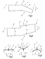
- FIG. 4 illustrates a back-sweep 15 which results is characterized in that in the region of the axis of rotation 3 for in Figure 4 not specified in detail end portion 1 a kink in the course of the rotor blade 1 against the direction of rotation (arrow 4) is present.
- the bend region is identified by the reference numeral 16; it exists between the leaf area 17 and the leaf area 18th
- the embodiment 5 shows a Vorpfeilung 19 between the sheet area 17 and the blade portion 18 is provided.
- the leaf area 18 is in the direction of rotation (arrow 4) as seen from the leaf area 17.
- the embodiment of Figure 6 corresponds to the embodiment of Figure 4, thus showing a scrubpfeilung 15, wherein in the Kink area 16, however, a jump in the degree of chord occurs.
- the chord 20 of the blade portion 17 is smaller than the chord 20 'formed in the sheet area 18.
- the rotation axis 3 closer sheet portion 17 may have a larger Wing depth as the leaf area further to the leaf end 18 have.
- the blade tip equipped with a wing extension 7 winglet
- Figures 7 to 9 show another feature. schematically in each case a rotor 21 is shown with two, diametrically opposite one another Rotor wing blades 2.
- the rotor 21 rotates about the Rotary axis 3, to which the plane of rotation 22 extends at right angles. extend the rotor blades 2 are in the plane of rotation 22, i.e. the rotor blade leaves 2 perpendicular to the axis of rotation 3, it follows the resulting from the figure 7 representation. Wear at the ends the rotor blade leaves 2 each creategelendfort engines. 7
- FIG. 8 illustrates that the rotor blade leaves 2 are not in the Rotary plane 22 must rotate, but-opposite to the wind direction 5- lie behind the plane of rotation, allowing them along in a conical surface rotate.
- the rotor blade leaves 2 are thus after Lee inclined.
- it is possible according to FIG. 9 that the rotor blade leaves are inclined in the direction of the windward direction, ie they are inclined in the wind direction 5 Seen before the plane of rotation 22, wherein the plane of rotation 22nd is defined so that it is perpendicular to the axis of rotation 3.
- the Rotor blade leaves 2 move in the embodiment of the figure 5 also along a conical surface.
Abstract
Description
Die Erfindung betrifft ein Rotorflügelblatt eines Rotors einer Windkraftanlage.The invention relates to a rotor blade of a rotor of a wind turbine.
Derartige Rotorflügelblätter sind vorzugsweise zu mehreren, winkelversetzt zueinander, an einer Nabe angeordnet. Sie führen zu einer Drehbewegung zur Erzeugung elektrischer Energie. Die Drehbewegung entsteht durch Windbeströmung der Rotorflügelblätter. Bekannte Rotorflügelblätter können im Betrieb durch die Windanströmung störende Geräusche erzeugen. Ferner stellen sie ein grundsätzlich nicht vermeidbaren Strömungswiderstand dar.Such rotor blade leaves are preferably to several angularly offset to each other, arranged on a hub. They lead to one Rotary movement for generating electrical energy. The rotational movement is caused by Windbeströmung the rotor blades. Known Rotor blade leaves can be operated by the Windanströmung generate disturbing noises. Furthermore, they constitute a principle unavoidable flow resistance.
Der Erfindung liegt die Aufgabe zugrunde, ein Rotorflügelblatt anzugeben, dass ohne Leistungseinbuße einen verminderten Strömungswiderstand aufweist und vorzugsweise überdies geräuschvermindert arbeitet.The invention has for its object to provide a rotor blade, that without loss of performance a reduced flow resistance and preferably also reduced in noise is working.
Diese Aufgabe wird gelöst mittels eines aerodynamischen Flügelendfortsatzes, dessen Fortsatzebene gegenüber der angrenzenden Flügelblattebene unter einem Winkel geneigt verläuft. Fortsatzebene und Flügelblattebene schließen somit einen Winkel ein, d.h., bei einem Blick entlang der Längsachse des Rotorflügelblatts zeigt sich, dass die Längsachse des Flügelendfortsatzes gegenüber der Längsachse des übrigen Rotorflügelblatts unter einem Winkel geneigt verläuft. Der Flügelendfortsatz bildet ein so genanntes "Winglet", das die aerodynamischen Eigenschaften des Rotorflügelblatts im Bereich seines freien Endes derart positiv aufgrund des geneigten Verlaufes des Flügelendfortsatzes beeinflusst, dass es bei gleicher oder erhöhter Leistungsabgabe zu einer Verminderung des Strömungswiderstandes und auch zur Geräuschverminderung kommt. Damit ergibt sich eine Verbesserung der aerodynamischen Wirksamkeit des Rotorflügelblattes, insbesondere auch im Blattaußenbereich. Dies gilt umso mehr, wenn das Rotorflügelblatt eine so genannte Tip-Bremse aufweist, d.h., ein Element an der Spitze, das bei Auslösung zu einer Abbremsung der Drehzahl führt. Ist der Flügelendfortsatz vorgesehen, so können dadurch Spalte zur Tip-Bremse vermieden werden, die widerstandsungünstig durchströmt würden.This object is achieved by means of an aerodynamic wing end extension, its extension plane opposite the adjacent Flügelblattebene is inclined at an angle. Extension level and vane plane thus enclose an angle, i.e. at one View along the longitudinal axis of the rotor wing blade shows, that the longitudinal axis of the Flügelendfortsatzes with respect to the longitudinal axis of the remaining rotor blade inclined at an angle runs. The Flügelendfortsatz forms a so-called "winglet", the the aerodynamic properties of the rotor wing blade in the area its free end so positive due to the inclined course of the wing-end-extension influences it with the same or increased Power output to reduce the flow resistance and also comes to noise reduction. This results an improvement in the aerodynamic efficiency of the rotor blade, especially in the leaf outer area. this applies even more so if the rotor blade leaf is a so-called tip-brake , that is, an element at the tip, which when triggered to a Braking the speed leads. Is the wing extension provided, so can be avoided column to the tip brake, would flow through the resistance unfavorable.
Nach einer Weiterbildung der Erfindung ist vorgesehen, dass der Flügelendfortsatz ein aerodynamisches Querschnittsprofil aufweist. Ebenso wie das übrige Rotorflügelblatt weist somit das Winglet ebenfalls eine Querschnittsstruktur auf, die ein aerodynamisches Profil besitzt.According to a development of the invention it is provided that the Flügelendfortsatz has an aerodynamic cross-sectional profile. Like the rest of the rotor blade, the winglet also has it a cross-sectional structure that has an aerodynamic profile has.
Ferner ist es von Vorteil, wenn der Flügelendfortsatz zur Oberseite des Rotorflügelblatts hin geneigt angeordnet ist. Alternativ ist es jedoch auch möglich, dass der Flügelendfortsatz zur Unterseite des Rotorflügelblatts hin geneigt angeordnet ist. Der Neigungswinkel liegt in einem Bereich, der einerseits durch eine nicht fluchtende Anordnung von Flügelendfortsatz und angrenzendem Rotorflügelblatt gekennzeichnet ist, bis zu einem Winkel von 90° zwischen diesen beiden Elementen. Der Winkel kann bis zu plus 90° oder bis zu minus 90° groß sein, je nach dem, ob der Flügelendfortsatz zur Oberseite oder zur Unterseite des Rotorflügelblatts hin geneigt angeordnet ist.Furthermore, it is advantageous if the Flügelendfortsatz to the top of the rotor blade is inclined. Alternatively, it is also possible that the wing end extension to the bottom of the Rotor wing blade is arranged inclined. The angle of inclination is in one area, on the one hand by a non-aligned arrangement characterized by wing extension and adjacent rotor blade is up to an angle of 90 ° between these two Elements. The angle can be up to plus 90 ° or up to minus 90 °, depending on whether the Flügelendfortsatz to the top or is arranged inclined to the bottom of the rotor blade.
Nach einer Weiterbildung der Erfindung ist vorgesehen, dass der Flügelendfortsatz zumindest über eine Teillänge eine kleinere Flügeltiefe als der angrenzende Bereich des Rotorflügelblatts aufweist. Mithin ist der Flügelendfortsatz schmaler ausgestaltet oder bereichsweise schmaler ausgestaltet als das angrenzende Rotorflügelblatt. Insbesondere kann auch vorgesehen sein, dass der Rotorendfortsatz zu seinem freien Ende hin in dem Maß seiner Flügeltiefe abnimmt, dass Ende also zugespitzt verläuft, wobei es nicht in einer punktförmigen Spitze enden muss, sondern auch abgeflacht sein kann. Bis in eine punktförmige Spitze auslaufende Winglets sind jedoch auch denkbar.According to a development of the invention it is provided that the Flügelendfortsatz at least over a partial length a smaller chord as the adjacent region of the rotor blade. Thus, the Flügelendfortsatz is narrower or regionally narrower designed as the adjacent rotor blade. In particular, it can also be provided that the rotor end extension to its free end in the measure of its chordal depth decreases, so that the end is tapered so it is not in one punctiform tip must end, but also be flattened can. However, winglets leaking into a punctiform tip are also conceivable.
Insbesondere ist vorgesehen, dass der Flügelendfortsatz asymmetrisch zur Rotorflügelblatt-Längsmittelachse ausgebildet ist. Die Asymmetrie kann in Drehrichtung voreilend oder in Drehrichtung rückeilend bestehen, d.h., der Flügelendfortsatz ist gegenüber der Rotorflügelblatt-Längsmittelachse versetzt angeordnet. Alternativ ist jedoch auch eine symmetrische Ausgestaltung denkbar.In particular, it is provided that the Flügelendfortsatz asymmetric is formed to the rotor blade longitudinal axis longitudinal axis. The asymmetry can be leading in the direction of rotation or lagging in the direction of rotation That is, the vane end extension is opposite the rotor vane longitudinal center axis staggered. Alternatively, however Also a symmetrical design conceivable.
Ferner kann vorgesehen sein, dass der Übergangsbereich von Flügelendfortsatz und angrenzendem Bereich des Rotorflügelblatts bezüglich der Fortsatzebene und der Flügelblattebene bogenförmig oder knickförmig ausgebildet ist. Bei einer bogenförmigen Anbindung erfolgt ein gekrümmt-kontinuierlicher Übergang zwischen den beiden Elementen; bei der knickförmigen Ausgestaltung ändert sich die Flügelebene abrupt.Furthermore, it can be provided that the transition region of Flügelendfortsatz and adjacent area of the rotor blade relative to the continuation plane and the wing blade plane arcuate or is formed kink-shaped. With a curved connection there is a curved-continuous transition between the two elements; in the crescent-shaped configuration, the wing plane changes abruptly.
Das Rotorflügelblatt kann mit einer Vorpfeilung oder einer Rückpfeilung versehen sein. Dies bedeutet, dass das Rotorblatt entlang seiner Längserstreckung keinen geradlinigen Verlauf aufweist, sondern einen abgeknickten Verlauf, wobei von "Vorpfeilung" geredet wird, wenn das abgeknickte freie Ende in Drehrichtung weist und von "Rückpfeilung", wenn das abgeknickte freie Ende entgegen die Drehrichtung zeigt. Die Vorpfeilung oder Rückpfeilung ist zusätzlich zum Flügelendfortsatz ausgebildet.The rotor blade can with a Vorpfeilung or a Rückpfeilung be provided. This means that the rotor blade along its Longitudinal extension does not have a straight course, but a bent course, whereby "Vorpfeilung" is spoken, when the kinked free end points in the direction of rotation and from "Rückpfeilung" when the kinked free end opposite to the direction of rotation shows. The Vorpfeilung or Rückpfeilung is in addition to Wing end extension formed.
Schließlich ist von Vorteil, wenn das Rotorflügelblatt im Knickbereich der Vorpfeilung oder Rückpfeilung eine Änderung in dem Maß der Flügeltiefe aufweist. Hierdurch werden vorteilhafte aerodynamische Eigenschaften erzielt, insbesondere dann, wenn der sich an die Abknickung anschließende, dem freien Ende zugewandte Abschnitt des Rotorflügelblatts eine größere Flügeltiefe aufweist, als der Abschnitt des Rotorflügelblatts, der der Nabe zugeordnet ist. Es sind auch mehrfach geknickte Vorpfeilungen oder Rückpfeilungen möglich.Finally, it is advantageous if the rotor blade in the kink area the forwarding or repatriation a change in the extent of Has chord depth. This will be advantageous aerodynamic Achieved properties, especially when the bend at the bend subsequent, the free end facing portion of the Rotor wing blade has a larger chord, than the section the rotor vane associated with the hub. There are too repeatedly kinked Vorpfeilungen or Rückpfeilungen possible.
Die Zeichnungen veranschaulichen die Erfindung anhand von Ausführungsbeispielen und zwar zeigt:
Figur 1- eine Seitenansicht auf einen Endabschnitt eines Rotorflügelblatts,
Figur 2- eine Draufsicht auf einen Endabschnitt eines Rotorflügelblatts,
Figur 3- eine weitere Ausführungsform entsprechend der
Darstellung der
Figur 2, Figur 4- eine Rückpfeilung eines Rotorflügelblatts,
Figur 5- eine Vorpfeilung eines Rotorflügelblatts,
Figur 6- ein weiteres Ausführungsbeispiel einer Vorpfeilung eines Rotorflügelblatts und
Figuren 7 bis 9- verschiedene, schematische Darstellungen betreffend die Drehebenen von unterschiedlichen Rotorflügelblättern.
- FIG. 1
- a side view of an end portion of a rotor blade,
- FIG. 2
- a plan view of an end portion of a rotor blade,
- FIG. 3
- a further embodiment according to the representation of Figure 2,
- FIG. 4
- a back sweep of a rotor wing blade,
- FIG. 5
- a pre-sharpening of a rotor wing blade,
- FIG. 6
- a further embodiment of a pre-sharpening of a rotor blade and
- FIGS. 7 to 9
- various schematic representations concerning the planes of rotation of different rotor blade leaves.
Die Figur 1 zeigt den freien Endbereich 1 eines nicht vollständig gezeichneten
Rotorflügelblatts 2. Das Rotorflügelblatt 2 rotiert durch
Windanströmung um eine nicht dargestellte Nabe, die eine Drehachse
3 aufweist. Beim Ausführungsbeispiel der Figur 1 erfolgt die Drehung
gemäß Pfeil 4 in die Zeichenebene hinein, d.h., von der Windrichtung
5 her betrachtet, im Uhrzeigersinn.FIG. 1 shows the
Das Rotorflügelblatt 2 weist einen Flügelblattendbereich 6 auf, der
bis zu einem Flügelendfortsatz 7 verläuft. Der Flügelendfortsatz 7
verläuft abgewinkelt zum Flügelblattendbereich 6. Diese beiden Elemente
stoßen in einem Übergangsbereich 8 aneinander, wobei
dieser Übergangsbereich bogenförmig gestaltet ist. Alternativ ist es
auch denkbar, dass der Übergangsbereich knickförmig ausgestaltet
ist. Betrachtet man die Flügelblattebene 9 des Flügelblattendbereichs
6 in Relation zur Fortsatzebene 10 des Flügelendfortsatzes 7,
so ist erkennbar, dass diese beiden Ebenen einen Winkel α von etwa
80° einschließen. Da -in Bezug auf die Windrichtung 5- der Flügelendfortsatz
7 in Richtung auf die Unterseite 11 des Rotorflügelblatts
2 abgewinkelt ist, kann dieser Winkel als negativer Winkel,
also minus 80°, bezeichnet werden. Alternativ ist es selbstverständlich
auch möglich, dass ein positiver Winkel α vorliegt (nicht dargestellt),
d.h., der Flügelendfortsatz 7 ist in Richtung auf die Oberseite
12 des Rotorflügelblatts 2 abgewinkelt, er weist damit in eine Richtung
entgegengesetzt zur Windrichtung 5. The
Der Winkel α kann als positiver oder negativer Winkel vorzugsweise
im Bereich von 90° bis < 180° liegen (180° erreicht der Winkel α
nicht, da dann der Flügelendfortsatz 7 fluchtend zum Flügelblattendbereich
6 verlaufen würde und nicht den erfindungsgemäß gewünschten,
geneigten Verlauf aufwiese).The angle α may preferably be a positive or negative angle
be in the range of 90 ° to <180 ° (180 ° reaches the angle α
not, because then the
Die Figur 2 zeigt ein weiteres Ausführungsbeispiel der Erfindung,
wobei die Drehachse 3 senkrecht auf der Zeichnungsebene steht
und der Flügelblattendbereich 6 entsprechend Pfeil 4 in der Zeichnungsebene
dreht. Gleiches gilt für die später noch abzuhandelnden
Darstellungen der Figuren 3 bis 6.FIG. 2 shows a further embodiment of the invention,
wherein the
Gemäß Figur 2 ist der gegenüber der Flügelblattebene 9 abgewinkelte
Flügelendfortsatz 7 asymmetrisch zur Rotorflügelblatt-Längsmittelachse
13 ausgestaltet, derart, dass er -gegenüber der
Drehrichtung (Pfeil 4)- nacheilend angeordnet ist.According to FIG. 2, the angle is angled relative to the vane plane 9
Beim Ausführungsbeispiel der Figur 3 liegt eine symmetrische Ausgestaltung
des Flügelendfortsatzes 7 zur Rotorflügelblatt-Längsmittelachse
13 vor, wobei dies aus der Zeichnung aufgrund
des entsprechenden Blickwinkels nicht eindeutig erkennbar ist. Zur
Verdeutlichung des Winkels α zwischen dem Flügelblattendbereich 6
und dem Flügelendfortsatz 7 ist dem Flügelendfortsatz 7 eine
Längsmittellinie 14 zugeordnet worden, die mit der Rotorflügelblatt-Längsmittelachse
13 den Winkel α bildet.In the embodiment of Figure 3 is a symmetrical configuration
the
Das Rotorflügelblatt 2 kann -zusätzlich zu der Ausbildung des Flügelendfortsatzes
7- mit einer Vorpfeilung oder einer Rückpfeilung
versehen sein. Die Figur 4 verdeutlicht eine Rückpfeilung 15, die dadurch
gekennzeichnet ist, dass im Bereich von der Drehachse 3 zum
in der Figur 4 nicht im Detail angegebenen Endbereich 1 ein Knick
im Verlauf des Rotorflügelblatts 1 entgegen der Drehrichtung (Pfeil
4) vorliegt. Der Knickbereich ist mit dem Bezugszeichen 16 gekennzeichnet;
er besteht zwischen dem Blattbereich 17 und dem Blattbereich
18.The
Im Gegensatz zum Ausführungsbeispiel der Figur 4 ist beim Ausführungsbeispiel
der Figur 5 eine Vorpfeilung 19 zwischen dem Blattbereich
17 und dem Blattbereich 18 vorgesehen. Der Blattbereich 18
eilt -in Drehrichtung (Pfeil 4) gesehen- dem Blattbereich 17 vor.In contrast to the embodiment of Figure 4 is the
Das Ausführungsbeispiel der Figur 6 entspricht dem Ausführungsbeispiel
der Figur 4, zeigt also eine Rückpfeilung 15, wobei in dem
Knickbereich 16 jedoch ein Sprung in dem Maß der Flügeltiefe erfolgt.
Die Flügeltiefe 20 des Blattbereichs 17 ist kleiner als die Flügeltiefe
20' im Blattbereich 18 ausgebildet. In einem nicht dargestellten
Ausführungsbeispiel kann dies auch umgekehrt der Fall sein, d.h.,
der der Drehachse 3 näher liegende Blattbereich 17 kann eine größere
Flügeltiefe als der weiter zum Blattende angeordnete Blattbereich
18 aufweisen. Stets ist jedoch dabei vorgesehen, dass die Flügelblattspitze
mit einem Flügelendfortsatz 7 (Winglet) ausgestattet
ist.The embodiment of Figure 6 corresponds to the embodiment
of Figure 4, thus showing a
Die Figuren 7 bis 9 zeigen eine weitere Besonderheit. Schematisch
dargestellt ist jeweils ein Rotor 21 mit zwei, einander diametral gegenüberliegenden
Rotorflügelblättern 2. Der Rotor 21 rotiert um die
Drehachse 3, zu der rechtwinklig die Drehebene 22 verläuft. Erstrecken
sich die Rotorflügelblätter 2 in der Drehebene 22, d.h., stehen
die Rotorflügelblätter 2 senkrecht auf der Drehachse 3, so ergibt sich
die aus der Figur 7 hervorgehende Darstellung. An den Enden tragen
die Rotorflügelblätter 2 jeweils Flügelendfortsätze 7. Figures 7 to 9 show another feature. schematically
in each case a
Die Figur 8 verdeutlicht, dass die Rotorflügelblätter 2 nicht in der
Drehebene 22 rotieren müssen, sondern -gegenüber der Windrichtung
5- hinter der Drehebene liegen, so dass sie entlang in einer Kegelmantelfläche
rotieren. Die Rotorflügelblätter 2 sind somit nach
Lee geneigt. Alternativ ist es gemäß Figur 9 möglich, dass die Rotorflügelblätter
in Luv-Richtung geneigt sind, sie also -in Windrichtung 5
gesehen- vor der Drehebene 22 liegen, wobei die Drehebene 22
derart definiert ist, dass sie senkrecht auf der Drehachse 3 steht. Die
Rotorflügelblätter 2 bewegen sich beim Ausführungsbeispiel der Figur
5 ebenfalls entlang einer Kegelmantelfläche.FIG. 8 illustrates that the rotor blade leaves 2 are not in the
Im Zuge dieser Anmeldung sind verschiedene Ausführungsformen erläutert und/oder in den Zeichnungen verdeutlicht worden. Es wird hiermit ausdrücklich erklärt, dass die verschiedenen Ausgestaltungen auch in beliebiger Art und Weise miteinander kombiniert werden können, also symmetrische und asymmetrische Winglets mit größeren oder kleineren Flügeltiefen, Vor- oder Rückpfeilungen, positiven oder negativen Winkeln der Flügelendfortsatzlage und so weiter, so dass jedes der Einzelmerkmale mit jedem anderen Einzelmerkmal oder einer Gruppe von anderen Einzelmerkmalen kombiniert werden kann.In the course of this application are various embodiments explained and / or illustrated in the drawings. It will hereby expressly states that the various configurations be combined with each other in any way can, so symmetrical and asymmetrical winglets with larger ones or smaller wing depths, forward or backward arrows, positive or negative angles of the wing tip position and so on, so that each of the individual features with each other individual feature or a group of other individual features can.
Claims (10)
Applications Claiming Priority (2)
| Application Number | Priority Date | Filing Date | Title |
|---|---|---|---|
| DE10332875.0A DE10332875B4 (en) | 2003-07-19 | 2003-07-19 | Rotor vane |
| DE10332875 | 2003-07-19 |
Publications (1)
| Publication Number | Publication Date |
|---|---|
| EP1500814A1 true EP1500814A1 (en) | 2005-01-26 |
Family
ID=33482975
Family Applications (1)
| Application Number | Title | Priority Date | Filing Date |
|---|---|---|---|
| EP04016618A Ceased EP1500814A1 (en) | 2003-07-19 | 2004-07-15 | Wind turbine rotor blade with wing tip |
Country Status (2)
| Country | Link |
|---|---|
| EP (1) | EP1500814A1 (en) |
| DE (1) | DE10332875B4 (en) |
Cited By (15)
| Publication number | Priority date | Publication date | Assignee | Title |
|---|---|---|---|---|
| WO2008077403A2 (en) * | 2006-12-22 | 2008-07-03 | Vestas Wind Systems A/S | Wind turbine with rotor blades equipped with winglets and blades for such rotor |
| EP1953383A1 (en) * | 2005-10-28 | 2008-08-06 | Gamesa Innovation & Technology, S.L. | Split-blade for wind generators |
| WO2009135902A3 (en) * | 2008-05-07 | 2010-06-10 | Vestas Wind Systems A/S | A sectional blade |
| EP2258941A1 (en) * | 2009-06-05 | 2010-12-08 | Jia-Yuan Lee | Wind turbine |
| US7914259B2 (en) | 2007-03-20 | 2011-03-29 | Vestas Wind Systems A/S | Wind turbine blades with vortex generators |
| WO2012117866A1 (en) * | 2011-02-28 | 2012-09-07 | 三菱重工業株式会社 | Wind turbine blade, wind-powered electricity generator provided with same, and method for designing wind turbine blade |
| WO2013083130A1 (en) * | 2011-12-09 | 2013-06-13 | Vestas Wind Systems A/S | Wind turbine including blades with suction side winglet |
| US8506255B2 (en) * | 2004-02-13 | 2013-08-13 | Aloys Wobben | Rotor blade for a wind turbine |
| DK178039B1 (en) * | 2010-11-16 | 2015-04-07 | Gen Electric | Wind turbine blade wing |
| US9039380B2 (en) | 2011-04-30 | 2015-05-26 | General Electric Company | Winglet for a wind turbine rotor blade |
| US9103325B2 (en) | 2012-03-20 | 2015-08-11 | General Electric Company | Winglet for a wind turbine rotor blade |
| DE102014115524A1 (en) | 2014-10-24 | 2016-04-28 | Nordex Energy Gmbh | Wind turbine rotor blade with a winglet |
| CN102338028B (en) * | 2010-07-16 | 2016-05-18 | 通用电气公司 | There is the wind turbine rotor blade of suction side winglet |
| US9388789B2 (en) | 2009-12-02 | 2016-07-12 | Vestas Wind Systems A/S | Sectional wind turbine blade |
| EP1596063B1 (en) | 2004-05-11 | 2016-09-28 | Senvion GmbH | Wind turbine with bent rotor blades |
Families Citing this family (4)
| Publication number | Priority date | Publication date | Assignee | Title |
|---|---|---|---|---|
| JP4740580B2 (en) * | 2004-11-30 | 2011-08-03 | 株式会社ベルシオン | Horizontal axis wind turbine blades and horizontal axis wind turbine |
| DE102007041649A1 (en) * | 2007-09-03 | 2009-03-05 | Daubner & Stommel GbR Bau-Werk-Planung (vertretungsberechtigter Gesellschafter: Matthias Stommel, 27777 Ganderkesee) | Rotor blade, wind energy plant and method for operating a wind turbine |
| JP5296141B2 (en) * | 2011-05-02 | 2013-09-25 | 株式会社ビルメン鹿児島 | Windmill wings for wind turbine generator |
| JP6009058B2 (en) * | 2013-02-26 | 2016-10-19 | 三菱重工業株式会社 | Wind turbine blade and wind power generator equipped with the same |
Citations (5)
| Publication number | Priority date | Publication date | Assignee | Title |
|---|---|---|---|---|
| US4324530A (en) * | 1980-01-21 | 1982-04-13 | United Technologies Corp. | Helicopter blade with a tip having a selected combination of sweep, taper and anhedral to improve hover efficiency |
| DE3621800A1 (en) | 1986-06-28 | 1988-01-07 | Riedelsheimer Hans Joachim | PLANE |
| EP0482932A1 (en) | 1990-10-24 | 1992-04-29 | Westland Helicopters Limited | Helicopter rotor blades |
| DE19963252A1 (en) | 1999-12-17 | 2001-07-12 | Lutz Schulze | Rotor blade for horizontal axis wind turbines is variable in longitudinal axis to increase rotor power, has base module attached to hub, module angled in the direction of rotation in rotor plane |
| DE10300284A1 (en) * | 2003-01-02 | 2004-07-15 | Aloys Wobben | Turbine rotor blade for wind-powered energy plant has tip region curved or angled in direction of rotor blade trailing edge |
Family Cites Families (2)
| Publication number | Priority date | Publication date | Assignee | Title |
|---|---|---|---|---|
| DE4241631C2 (en) * | 1992-12-10 | 1994-11-24 | Peter Dipl Ing Frieden | Wind turbine |
| DE19738278A1 (en) * | 1997-09-02 | 1999-03-04 | Felix Hafner | Adaptive rotor for wind power plants |
-
2003
- 2003-07-19 DE DE10332875.0A patent/DE10332875B4/en not_active Expired - Fee Related
-
2004
- 2004-07-15 EP EP04016618A patent/EP1500814A1/en not_active Ceased
Patent Citations (5)
| Publication number | Priority date | Publication date | Assignee | Title |
|---|---|---|---|---|
| US4324530A (en) * | 1980-01-21 | 1982-04-13 | United Technologies Corp. | Helicopter blade with a tip having a selected combination of sweep, taper and anhedral to improve hover efficiency |
| DE3621800A1 (en) | 1986-06-28 | 1988-01-07 | Riedelsheimer Hans Joachim | PLANE |
| EP0482932A1 (en) | 1990-10-24 | 1992-04-29 | Westland Helicopters Limited | Helicopter rotor blades |
| DE19963252A1 (en) | 1999-12-17 | 2001-07-12 | Lutz Schulze | Rotor blade for horizontal axis wind turbines is variable in longitudinal axis to increase rotor power, has base module attached to hub, module angled in the direction of rotation in rotor plane |
| DE10300284A1 (en) * | 2003-01-02 | 2004-07-15 | Aloys Wobben | Turbine rotor blade for wind-powered energy plant has tip region curved or angled in direction of rotor blade trailing edge |
Cited By (22)
| Publication number | Priority date | Publication date | Assignee | Title |
|---|---|---|---|---|
| US8506255B2 (en) * | 2004-02-13 | 2013-08-13 | Aloys Wobben | Rotor blade for a wind turbine |
| EP1596063B1 (en) | 2004-05-11 | 2016-09-28 | Senvion GmbH | Wind turbine with bent rotor blades |
| EP1953383A4 (en) * | 2005-10-28 | 2012-12-05 | Gamesa Innovation & Tech Sl | Split-blade for wind generators |
| EP1953383A1 (en) * | 2005-10-28 | 2008-08-06 | Gamesa Innovation & Technology, S.L. | Split-blade for wind generators |
| US7931444B2 (en) * | 2006-12-22 | 2011-04-26 | Vestas Wind Systems A/S | Wind turbine with rotor blades equipped with winglets and blades for such rotor |
| AU2007336537B2 (en) * | 2006-12-22 | 2011-05-26 | Vestas Wind Systems A/S | Wind turbine with rotor blades equipped with winglets and blades for such rotor |
| WO2008077403A2 (en) * | 2006-12-22 | 2008-07-03 | Vestas Wind Systems A/S | Wind turbine with rotor blades equipped with winglets and blades for such rotor |
| WO2008077403A3 (en) * | 2006-12-22 | 2008-11-27 | Vestas Wind Sys As | Wind turbine with rotor blades equipped with winglets and blades for such rotor |
| US7914259B2 (en) | 2007-03-20 | 2011-03-29 | Vestas Wind Systems A/S | Wind turbine blades with vortex generators |
| US9765756B2 (en) | 2008-05-07 | 2017-09-19 | Vestas Wind Systems A/S | Sectional blade |
| WO2009135902A3 (en) * | 2008-05-07 | 2010-06-10 | Vestas Wind Systems A/S | A sectional blade |
| EP2258941A1 (en) * | 2009-06-05 | 2010-12-08 | Jia-Yuan Lee | Wind turbine |
| US9388789B2 (en) | 2009-12-02 | 2016-07-12 | Vestas Wind Systems A/S | Sectional wind turbine blade |
| CN102338028B (en) * | 2010-07-16 | 2016-05-18 | 通用电气公司 | There is the wind turbine rotor blade of suction side winglet |
| DK178039B1 (en) * | 2010-11-16 | 2015-04-07 | Gen Electric | Wind turbine blade wing |
| WO2012117866A1 (en) * | 2011-02-28 | 2012-09-07 | 三菱重工業株式会社 | Wind turbine blade, wind-powered electricity generator provided with same, and method for designing wind turbine blade |
| US9039380B2 (en) | 2011-04-30 | 2015-05-26 | General Electric Company | Winglet for a wind turbine rotor blade |
| WO2013083130A1 (en) * | 2011-12-09 | 2013-06-13 | Vestas Wind Systems A/S | Wind turbine including blades with suction side winglet |
| US9103325B2 (en) | 2012-03-20 | 2015-08-11 | General Electric Company | Winglet for a wind turbine rotor blade |
| US10047719B2 (en) | 2012-03-20 | 2018-08-14 | General Electric Company | Winglet for a wind turbine rotor blade |
| EP2828521B1 (en) | 2012-03-20 | 2019-02-27 | General Electric Company | Winglet for a wind turbine rotor blade |
| DE102014115524A1 (en) | 2014-10-24 | 2016-04-28 | Nordex Energy Gmbh | Wind turbine rotor blade with a winglet |
Also Published As
| Publication number | Publication date |
|---|---|
| DE10332875A1 (en) | 2005-02-17 |
| DE10332875B4 (en) | 2016-11-24 |
Similar Documents
| Publication | Publication Date | Title |
|---|---|---|
| EP1500814A1 (en) | Wind turbine rotor blade with wing tip | |
| EP1801422B1 (en) | Fan and fan blade | |
| DE60125172T2 (en) | ROTOR BLADE FOR A WIND POWER PLANT | |
| DE2744366A1 (en) | IMPELLER FOR A RADIAL TURBO COMPRESSOR | |
| EP2469077A2 (en) | Rotor blade for a wind energy facility | |
| EP2366891B1 (en) | Wind turbine rotor blade | |
| EP1923567A2 (en) | Rotor blade and wind turbine | |
| EP3655664A1 (en) | Vanes for the impeller of a ventilator, impeller, and axial ventilator, diagonal ventilator, or radial ventilator | |
| EP2145102A2 (en) | Supporting arm for the blades of wind turbines with a vertical rotational axis | |
| DE2621982C2 (en) | ||
| EP2366892B1 (en) | Wind turbine rotor blade | |
| EP1244872A1 (en) | Rotor blade for a wind power installation | |
| WO2015062710A1 (en) | Rotor blade of a wind turbine and a wind turbine | |
| EP3702620A1 (en) | Axial fan with noise reducing fan impeller vanes having bores | |
| EP3169898B1 (en) | Wind-turbine rotor blade, trailing edge for wind-turbine rotor blade tip, method for producing a wind-turbine rotor blade, and wind turbine | |
| EP2568166B1 (en) | Wind energy assembly rotor blade with a thick profile trailing edge | |
| DE1428273B2 (en) | Impeller for a low-noise axial fan | |
| DE3014872C2 (en) | Plastic fan wheel | |
| DD288649A5 (en) | RADIAL FAN | |
| DE3234011A1 (en) | Axial fan | |
| DE102004038639A1 (en) | Francis turbine for the generation of hydro-electricity has blade profile ratio minimizing trailing edge vortices | |
| DE2845561A1 (en) | AUTOMOTIVE RADIATOR FAN | |
| WO1998026176A1 (en) | Water turbine or water pump | |
| DE3108507C2 (en) | ||
| DE19709818B4 (en) | submersible agitator |
Legal Events
| Date | Code | Title | Description |
|---|---|---|---|
| PUAI | Public reference made under article 153(3) epc to a published international application that has entered the european phase |
Free format text: ORIGINAL CODE: 0009012 |
|
| AK | Designated contracting states |
Kind code of ref document: A1 Designated state(s): AT BE BG CH CY CZ DE DK EE ES FI FR GB GR HU IE IT LI LU MC NL PL PT RO SE SI SK TR |
|
| AX | Request for extension of the european patent |
Extension state: AL HR LT LV MK |
|
| 17P | Request for examination filed |
Effective date: 20050726 |
|
| AKX | Designation fees paid |
Designated state(s): AT BE BG CH CY CZ DE DK EE ES FI FR GB GR HU IE IT LI LU MC NL PL PT RO SE SI SK TR |
|
| AXX | Extension fees paid |
Extension state: HR Payment date: 20050726 |
|
| RAP1 | Party data changed (applicant data changed or rights of an application transferred) |
Owner name: FC HOLDING GMBH |
|
| 17Q | First examination report despatched |
Effective date: 20101026 |
|
| RAP1 | Party data changed (applicant data changed or rights of an application transferred) |
Owner name: WINDREICH AG |
|
| APBK | Appeal reference recorded |
Free format text: ORIGINAL CODE: EPIDOSNREFNE |
|
| APBN | Date of receipt of notice of appeal recorded |
Free format text: ORIGINAL CODE: EPIDOSNNOA2E |
|
| APBR | Date of receipt of statement of grounds of appeal recorded |
Free format text: ORIGINAL CODE: EPIDOSNNOA3E |
|
| APAF | Appeal reference modified |
Free format text: ORIGINAL CODE: EPIDOSCREFNE |
|
| APBT | Appeal procedure closed |
Free format text: ORIGINAL CODE: EPIDOSNNOA9E |
|
| STAA | Information on the status of an ep patent application or granted ep patent |
Free format text: STATUS: THE APPLICATION HAS BEEN REFUSED |
|
| 18R | Application refused |
Effective date: 20130816 |