EP1406012A1 - Bearing and braking system for the nacelle of a wind turbine - Google Patents
Bearing and braking system for the nacelle of a wind turbine Download PDFInfo
- Publication number
- EP1406012A1 EP1406012A1 EP03021887A EP03021887A EP1406012A1 EP 1406012 A1 EP1406012 A1 EP 1406012A1 EP 03021887 A EP03021887 A EP 03021887A EP 03021887 A EP03021887 A EP 03021887A EP 1406012 A1 EP1406012 A1 EP 1406012A1
- Authority
- EP
- European Patent Office
- Prior art keywords
- ring
- clamping
- machine head
- tower
- jaws
- Prior art date
- Legal status (The legal status is an assumption and is not a legal conclusion. Google has not performed a legal analysis and makes no representation as to the accuracy of the status listed.)
- Withdrawn
Links
- 239000012530 fluid Substances 0.000 claims abstract description 11
- 230000002706 hydrostatic effect Effects 0.000 claims abstract description 6
- 238000011144 upstream manufacturing Methods 0.000 claims description 6
- 230000015572 biosynthetic process Effects 0.000 claims description 2
- 239000000463 material Substances 0.000 claims description 2
- 238000003825 pressing Methods 0.000 claims description 2
- 230000003068 static effect Effects 0.000 claims description 2
- 230000001050 lubricating effect Effects 0.000 claims 1
- 238000003860 storage Methods 0.000 description 4
- 230000007423 decrease Effects 0.000 description 3
- 230000005484 gravity Effects 0.000 description 3
- 238000012423 maintenance Methods 0.000 description 3
- 238000005096 rolling process Methods 0.000 description 3
- 238000004026 adhesive bonding Methods 0.000 description 1
- 238000005452 bending Methods 0.000 description 1
- 238000010276 construction Methods 0.000 description 1
- 238000010586 diagram Methods 0.000 description 1
- 238000009434 installation Methods 0.000 description 1
- 239000007788 liquid Substances 0.000 description 1
- 238000005461 lubrication Methods 0.000 description 1
- 230000002093 peripheral effect Effects 0.000 description 1
- 238000000926 separation method Methods 0.000 description 1
Images


Classifications
-
- F—MECHANICAL ENGINEERING; LIGHTING; HEATING; WEAPONS; BLASTING
- F16—ENGINEERING ELEMENTS AND UNITS; GENERAL MEASURES FOR PRODUCING AND MAINTAINING EFFECTIVE FUNCTIONING OF MACHINES OR INSTALLATIONS; THERMAL INSULATION IN GENERAL
- F16C—SHAFTS; FLEXIBLE SHAFTS; ELEMENTS OR CRANKSHAFT MECHANISMS; ROTARY BODIES OTHER THAN GEARING ELEMENTS; BEARINGS
- F16C41/00—Other accessories, e.g. devices integrated in the bearing not relating to the bearing function as such
- F16C41/001—Integrated brakes or clutches for stopping or coupling the relatively movable parts
-
- F—MECHANICAL ENGINEERING; LIGHTING; HEATING; WEAPONS; BLASTING
- F03—MACHINES OR ENGINES FOR LIQUIDS; WIND, SPRING, OR WEIGHT MOTORS; PRODUCING MECHANICAL POWER OR A REACTIVE PROPULSIVE THRUST, NOT OTHERWISE PROVIDED FOR
- F03D—WIND MOTORS
- F03D7/00—Controlling wind motors
- F03D7/02—Controlling wind motors the wind motors having rotation axis substantially parallel to the air flow entering the rotor
- F03D7/0204—Controlling wind motors the wind motors having rotation axis substantially parallel to the air flow entering the rotor for orientation in relation to wind direction
-
- F—MECHANICAL ENGINEERING; LIGHTING; HEATING; WEAPONS; BLASTING
- F03—MACHINES OR ENGINES FOR LIQUIDS; WIND, SPRING, OR WEIGHT MOTORS; PRODUCING MECHANICAL POWER OR A REACTIVE PROPULSIVE THRUST, NOT OTHERWISE PROVIDED FOR
- F03D—WIND MOTORS
- F03D80/00—Details, components or accessories not provided for in groups F03D1/00 - F03D17/00
- F03D80/70—Bearing or lubricating arrangements
-
- F—MECHANICAL ENGINEERING; LIGHTING; HEATING; WEAPONS; BLASTING
- F16—ENGINEERING ELEMENTS AND UNITS; GENERAL MEASURES FOR PRODUCING AND MAINTAINING EFFECTIVE FUNCTIONING OF MACHINES OR INSTALLATIONS; THERMAL INSULATION IN GENERAL
- F16C—SHAFTS; FLEXIBLE SHAFTS; ELEMENTS OR CRANKSHAFT MECHANISMS; ROTARY BODIES OTHER THAN GEARING ELEMENTS; BEARINGS
- F16C32/00—Bearings not otherwise provided for
- F16C32/06—Bearings not otherwise provided for with moving member supported by a fluid cushion formed, at least to a large extent, otherwise than by movement of the shaft, e.g. hydrostatic air-cushion bearings
- F16C32/0681—Construction or mounting aspects of hydrostatic bearings, for exclusively rotary movement, related to the direction of load
- F16C32/0696—Construction or mounting aspects of hydrostatic bearings, for exclusively rotary movement, related to the direction of load for both radial and axial load
-
- F—MECHANICAL ENGINEERING; LIGHTING; HEATING; WEAPONS; BLASTING
- F16—ENGINEERING ELEMENTS AND UNITS; GENERAL MEASURES FOR PRODUCING AND MAINTAINING EFFECTIVE FUNCTIONING OF MACHINES OR INSTALLATIONS; THERMAL INSULATION IN GENERAL
- F16C—SHAFTS; FLEXIBLE SHAFTS; ELEMENTS OR CRANKSHAFT MECHANISMS; ROTARY BODIES OTHER THAN GEARING ELEMENTS; BEARINGS
- F16C2300/00—Application independent of particular apparatuses
- F16C2300/10—Application independent of particular apparatuses related to size
- F16C2300/14—Large applications, e.g. bearings having an inner diameter exceeding 500 mm
-
- F—MECHANICAL ENGINEERING; LIGHTING; HEATING; WEAPONS; BLASTING
- F16—ENGINEERING ELEMENTS AND UNITS; GENERAL MEASURES FOR PRODUCING AND MAINTAINING EFFECTIVE FUNCTIONING OF MACHINES OR INSTALLATIONS; THERMAL INSULATION IN GENERAL
- F16C—SHAFTS; FLEXIBLE SHAFTS; ELEMENTS OR CRANKSHAFT MECHANISMS; ROTARY BODIES OTHER THAN GEARING ELEMENTS; BEARINGS
- F16C2360/00—Engines or pumps
- F16C2360/31—Wind motors
-
- Y—GENERAL TAGGING OF NEW TECHNOLOGICAL DEVELOPMENTS; GENERAL TAGGING OF CROSS-SECTIONAL TECHNOLOGIES SPANNING OVER SEVERAL SECTIONS OF THE IPC; TECHNICAL SUBJECTS COVERED BY FORMER USPC CROSS-REFERENCE ART COLLECTIONS [XRACs] AND DIGESTS
- Y02—TECHNOLOGIES OR APPLICATIONS FOR MITIGATION OR ADAPTATION AGAINST CLIMATE CHANGE
- Y02E—REDUCTION OF GREENHOUSE GAS [GHG] EMISSIONS, RELATED TO ENERGY GENERATION, TRANSMISSION OR DISTRIBUTION
- Y02E10/00—Energy generation through renewable energy sources
- Y02E10/70—Wind energy
- Y02E10/72—Wind turbines with rotation axis in wind direction
Definitions
- the invention relates to a device for mounting the machine head Wind turbine on the carrier tower, with one arranged on the tower Bearing on which the machine head with the rotor around a vertical axis is rotatable, and with a clamping device for locking the machine head on Carrier tower in a desired rotational position.
- Rolling or plain bearings are conventionally used on the carrier tower, which are able to absorb tilting moments acting on the machine head. Such tilting moments result on the one hand from the load on the side of the spire of the protruding machine head. On the other hand, he cares in particular wind attacking the rotor blades for large horizontal thrust forces as well as tilting moments around all three head axes.
- the one to adapt to the wind direction machine head rotatable by a drive device after twisting to lock in the new rotational position again, using the clamping device also serves to relieve the pivot bearing arranged on the support tower and thereby keeping its wear low.
- the clamping device more conventional Storage devices comprises a clamping disk connected to the carrier tower which jaws connected to the machine head in the manner of a Apply the disc brake. As long as the machine head is not turned, acts on the jaws constantly apply hydraulic pressure or the force of a spring.
- the present invention has for its object a new storage device of the type mentioned at the outset, compared to known ones Devices with reduced wear require less maintenance.
- the device achieving this object according to the invention is characterized by Devices formed in the manner of a hydrostatic bearing with a high pressure pump for the generation of a pressure fluid film between the clamping surfaces of the Clamping device.
- the clamping surfaces are during the rotation of the machine head the clamping device is lifted from each other by the pressure fluid film and the machine head can be easily rotated. That through the high pressure pump conveyed pressure medium, preferably oil, can, one between the clamping surfaces form the flowing liquid film of the clamping device. That through the film from each other lifted clamping surfaces move against each other wear and tear frictionless.
- the high pressure pump conveyed pressure medium preferably oil
- the clamping device comprises a ring attached to the tower or head and against the ring with the jaws connected to the head or tower, covering the circumference of the ring distributed a number of such jaws and in the abutting against the ring Clamping surfaces of the jaws via a pressure line with the high pressure pump connected pockets are formed.
- the clamping device for locking the machine head in Combination with a roller bearing or the rotary bearing mentioned at the beginning To use plain bearings is in the preferred embodiment of the invention Rotary bearing of the machine head only through the ring and during the Rotation of the machine head hydrostatically relieved clamping jaws itself formed.
- the machine head can be stored on the tower without any friction. The construction of the head and tower is simplified.
- the cross section of the opening of the pockets facing the ring and / or the Size of the clamping surfaces could vary around the circumference of the ring Tipping moment to be taken into account by the lateral overhang of the head is generated and is always effective.
- Clamping jaws can be used in the manner of pliers on both ends of the ring Apply the disc brake or only on one end of the ring.
- the jaws rest like pliers against conical surfaces of the ring.
- the ring and the hydrostatically relieved clamping jaws are advantageous a plain bearing in which the machine head both axially and radially is led.
- a second ring connected to the machine head or tower and on the second Ring forming the clamping surfaces, preferably with a material high coefficient of static friction, as well as the second ring against the first Ring-pressing clamping device is provided.
- the second ring integrally connected to a supporting housing of the machine head and Flanged like an opening of the machine head facing the top of the tower.
- a third arranged by the clamping device against the first ring ring his.
- This third ring can be covered with coverings to form additional jaws, wherein the jaws of the second and third rings like pliers on the attack the first ring.
- the third ring can be a roller or slide bearing be stored on the first ring.
- you can ring segments can also be used.
- the rings can be used as a carrier for clamping jaws Housing of the machine head or foot parts protruding from the tower wall form, which are detachably connected to the housing or the tower wall and with reduction of the maintenance effort are individually interchangeable.
- Such foot pieces could also connected to a ring corresponding to the second and / or third ring his.
- Said tensioning device can connect the second and third rings Have screws.
- Tension member into consideration that on the machine head or tower around the axis of rotation of the machine head rotatably and e.g. through a bolt or a Traction rope is formed.
- a preferably ring-shaped Collecting channel for the pressure fluid delivered by the high pressure pump is formed be, which is part of a pressure fluid circuit.
- the pressure fluid circulated in a circuit can also advantageously be used for lubrication serve a rotary drive for the machine head.
- a tower of a wind turbine is designated.
- the tower 1 carries a machine head 2 with a wind rotor 3 and a supporting housing 4.
- a generator not shown in FIGS. 1 to 3, driven by the wind rotor 3 accommodated.
- the wind rotor 3 rotates about a horizontal axis 5.
- the tower 1 is rotatable about a vertical axis 6.
- Arrows 7 and 8 indicate that a pivot bearing arranged at 9 has tilting moments is exposed, on the one hand, to the load of the laterally overhanging machine head 2 and on the other hand result from wind forces that are horizontal at the machine head attack.
- the pivot bearing 9 comprises a screwed to the tower 1 Ring 10 with an external toothing 11.
- a toothed wheel engages in the external toothing 11 one connected to the housing 4 of the machine head 2, not in FIGS. 1 to 3 shown drive device for the rotation of the head 2.
- jaws 13 to 15 In the embodiment in question there are twenty clamping jaws 13, 14 in each case or 15 formed.
- Each of the friction linings 16 fastened by gluing to the ring in question has a pocket 17 which opens towards the ring 10 and which is connected via a pressure line 18 communicates with a high pressure pump 19.
- the friction lining 16 can e.g. as Ronde be formed with a pocket concentric with the outer circumference.
- everybody Pocket 17 is a flow resistance 20, e.g. in the form of a capillary, upstream.
- the second ring 12 is in one piece with the housing 4 as a flange-like expansion of the Formed housing wall and has a step.
- the third ring 21 can be with the Screw the second ring 12, the jaws 13 and 14 with the ring 10 be tense.
- the thickness of the ring 10 is compared to the height of the step in the ring 12 selected so that there is scope for such tension. Facilities for Radial bracing of the inner jaws 15 with the ring 10 are not shown.
- the head 2 must be rotated to adapt the position of the wind rotor 3 to the wind direction be, the pockets 17 with the help of the high pressure pump 19 on the Pressure lines 18 supplied oil as a pressure medium, builds up in the pockets 17 against the clamping force of the jaws is so high that the oil between the Clamping surfaces of the friction linings 16 and the relevant surface of the ring 10 occurs to the outside, a friction largely canceling out between these surfaces Oil film 22 of thickness h is formed. The separation of the clamping surfaces by the Oil film 22 ensures that the bearing of the machine head 2 is completely free of wear the tower 1.
- the ring 10 and the jaws 13 to 15 form a smooth-running, the machine head 2 axially and radially leading hydrostatic plain bearings on which the (not shown) engaging in the external teeth 11 of the ring 10 the drive device Can easily rotate rotor / generator assembly.
- the oil emerging from the friction linings 16 passes through collecting channels (not shown) and lines in a circuit back into the high pressure pump 19.
- the internal pressure pi falls along the pocket 17 the diameter portions ⁇ x of the oil film 22 flowing outward to the Value 0 or the external pressure.
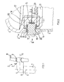
- FIG. 4 differs from the embodiment from Fig. 1 to 3 in that clamping or sliding bearing surfaces one with a tower 1a connected ring 10a not parallel to each other but inclined to each other and are conical. This measure allows for a reduced number of jaws achieve both axial and radial guidance of the machine head. Furthermore, it is ensured that the ring 10a, on the housing 4a of a machine head 2a not formed second ring 12a and a third ring 21 a screwable with it are deformed and twisted by attacking tilting moments so that the Can lift the pockets of the hydrostatic bearing on one side. That is based on 5 explained in more detail.
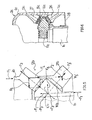
- a force equilibrium results, provided that the hydrostatically relieved clamping or bearing parts can move smoothly on a conical ring 10b on the tower side , which prevents bending and twisting of the individual rings 10b, 12b and 21b.
- the two closed rings 12b, 21b are under tensile stress when expanded by the pressure fluid, and the ring 10b is radially compressed.
- a vertical external force F 1 which together with a pretensioning force F 2 , which is generated, for example, according to FIG.
- the tensioning force F 2 ensures a tension restoring force F 5 ', F 2 and F 5 ' being in equilibrium with the pocket force F 3 'acting on the ring 21 and the three forces intersecting in the center of gravity of the cross-sectional area 21b.
- the lines of action of the forces F 3 and F 3 ' also meet in the center of gravity of the cross-sectional area of the ring 10b. Together with a tension restoring force F 6 of the ring 10b, there is an equilibrium of the forces F 6 , -F 1 , -F 3 and F 3 ', so that rotation of the ring 10b under any load F 1 is also avoided.
- a housing 4c has a machine head 2c no ring, but from the housing protruding foot parts 26 and 27 for the Formation of jaws 13c and 14c on the circumference of a ring 10c are distributed.
- the foot parts 26, 27 can be detachably connected to the housing 4c, what an exchange of individual jaws and thus the maintenance of the bearing device facilitated.
- a ring 10c connected to the tower 1c has teeth on its inside 11c, which has the same function as the external toothing 11 of the exemplary embodiment of Fig. 2 comes. With this design there are deformation properties as achieved in the embodiment of FIG. 5, the housing wall 4c takes over the function of the rings 12b and 21b.
- Reference numeral 28 in Fig. 6 indicates a gutter for collecting in the high pressure pump oil to be returned.
- Fig. 7 shows an embodiment in which a wrap for a ring 10d a ring 21 d is formed, which is rotatable via rolling elements 31 on the ring 10d and biased by screws 32 connected to a ring 12d on the housing 4d is.
- drive means denotes a motor and a gearwheel 34, which is in an external toothing 11e of a ring 10e engages.
Abstract
Description
Die Erfindung betrifft eine Vorrichtung zur Lagerung des Maschinenkopfes einer Windenergieanlage auf dem Trägerturm, mit einem auf dem Turm angeordneten Lager, auf dem der den Rotor aufweisende Maschinenkopf um eine vertikale Achse drehbar ist, und mit einer Klemmeinrichtung zur Arretierung des Maschinenkopfes am Trägerturm in einer gewünschten Drehposition.The invention relates to a device for mounting the machine head Wind turbine on the carrier tower, with one arranged on the tower Bearing on which the machine head with the rotor around a vertical axis is rotatable, and with a clamping device for locking the machine head on Carrier tower in a desired rotational position.
Zur Lagerung der Rotor-/Generatorbaugruppe bzw. Maschinenkopfes einer Windenergieanlage auf dem Trägerturm werden herkömmlich Wälz- oder Gleitlager eingesetzt, die in der Lage sind, am Maschinenkopf angreifende Kippmomente abzutragen. Solche Kippmomente ergeben sich einerseits durch die Last des seitlich von der Trägerturmspitze vorstehenden Maschinenkopfs. Andererseits sorgt der insbesondere an den Rotorblättern angreifende Wind für große horizontale Schubkräfte sowie Kippmomente um alle drei Kopfachsen. Der zur Anpassung an die Windrichtung durch eine Antriebseinrichtung drehbare Maschinenkopf ist nach einer Verdrehung in der neuen Drehposition wieder zu arretieren, wobei die Klemmeinrichtung ferner dazu dient, das auf dem Trägerturm angeordnete Drehlager zu entlasten und dadurch seinen Verschleiß gering zu halten. Die Klemmeinrichtung herkömmlicher Lagervorrichtungen umfasst eine mit dem Trägerturm verbundene Klemmscheibe, an welcher mit dem Maschinenkopf verbundene Klemmbacken in der Art einer Scheibenbremse angreifen. Solange der Maschinenkopf nicht gedreht wird, wirkt auf die Klemmbacken ständig ein Hydraulikdruck oder die Kraft einer Feder ein. For mounting the rotor / generator assembly or machine head of a wind turbine Rolling or plain bearings are conventionally used on the carrier tower, which are able to absorb tilting moments acting on the machine head. Such tilting moments result on the one hand from the load on the side of the spire of the protruding machine head. On the other hand, he cares in particular wind attacking the rotor blades for large horizontal thrust forces as well as tilting moments around all three head axes. The one to adapt to the wind direction machine head rotatable by a drive device after twisting to lock in the new rotational position again, using the clamping device also serves to relieve the pivot bearing arranged on the support tower and thereby keeping its wear low. The clamping device more conventional Storage devices comprises a clamping disk connected to the carrier tower which jaws connected to the machine head in the manner of a Apply the disc brake. As long as the machine head is not turned, acts on the jaws constantly apply hydraulic pressure or the force of a spring.
Aus der DE 199 62 978 C1 ist es bekannt, zur Lagerung des Maschinenkopfs auf dem Turm ein Gleitlager zu verwenden, welches den Maschinenkopf bezogen auf die Turmachse sowohl in radialer als auch axialer Richtung führt.From DE 199 62 978 C1 it is known to mount the machine head on the Tower to use a plain bearing, which refers to the machine head on the Tower axis leads in both the radial and axial directions.
Der vorliegenden Erfindung liegt die Aufgabe zugrunde, eine neue Lagerungsvorrichtung der eingangs erwähnten Art zu schaffen, die gegenüber bekannten solchen Vorrichtungen bei gemindertem Verschleiß einen geringeren Wartungsaufwand erfordert.The present invention has for its object a new storage device of the type mentioned at the outset, compared to known ones Devices with reduced wear require less maintenance.
Die diese Aufgabe lösende Vorrichtung nach der Erfindung ist gekennzeichnet durch in der Art einer hydrostatischen Lagerung gebildete Einrichtungen mit einer Hochdruckpumpe für die Erzeugung eines Druckfluidfilms zwischen den Klemmflächen der Klemmeinrichtung.The device achieving this object according to the invention is characterized by Devices formed in the manner of a hydrostatic bearing with a high pressure pump for the generation of a pressure fluid film between the clamping surfaces of the Clamping device.
Gemäß der Erfindung sind während der Drehung des Maschinenkopfes die Klemmflächen der Klemmeinrichtung durch den Druckfluidfilm voneinander abgehoben und der Maschinenkopf dadurch leicht drehbar. Das durch die Hochdruckpumpe geförderte Druckmedium, vorzugsweise Öl, kann,einen zwischen den Klemmflächen der Klemmeinrichtung strömenden Flüssigkeitsfilm bilden. Die durch den Film voneinander abgehobenen Klemmflächen bewegen sich gegeneinander verschleiß- und reibungsfrei.According to the invention, the clamping surfaces are during the rotation of the machine head the clamping device is lifted from each other by the pressure fluid film and the machine head can be easily rotated. That through the high pressure pump conveyed pressure medium, preferably oil, can, one between the clamping surfaces form the flowing liquid film of the clamping device. That through the film from each other lifted clamping surfaces move against each other wear and tear frictionless.
In der bevorzugten Ausführungsform der Erfindung umfasst die Klemmeinrichtung einen am Turm oder Kopf angebrachten Ring und gegen den Ring anliegende, mit dem Kopf bzw. Turm verbundene Klemmbacken, wobei über den Umfang des Rings eine Anzahl solcher Klemmbacken verteilt und in den gegen den Ring anliegenden Klemmflächen der Klemmbacken über eine Druckleitung mit der Hochdruckpumpe verbundene Taschen gebildet sind.In the preferred embodiment of the invention, the clamping device comprises a ring attached to the tower or head and against the ring with the jaws connected to the head or tower, covering the circumference of the ring distributed a number of such jaws and in the abutting against the ring Clamping surfaces of the jaws via a pressure line with the high pressure pump connected pockets are formed.
Greifen am Maschinenkopf Kippmomente an, so werden die über den Umfang des Rings verteilten Klemmbacken unterschiedlich belastet. Bei Anschluss der Taschen aller Klemmbacken an eine einzige Hochdruckpumpe kann sich im Falle besonders starker Belastung einzelner Klemmbacken während einer Drehung des Maschinenkopfes der Pumpendruck wegen der parallelen Anordnung der Druckleitungen nicht entsprechend erhöhen und die Druckfluidströmung durch die Taschen der betreffenden Klemmbacken käme zum Erliegen. Während es denkbar aber sehr aufwendig wäre, jedem Klemmbacken eine nur ihn versorgende Hochdruckpumpe zuzuordnen, sind in einer besonders bevorzugten Ausführungsform der Erfindung mehrere oder alle Klemmbacken jeweils über einen der Tasche vorgeordneten Strömungswiderstand mit einer einzigen Hochdruckpumpe verbunden. Ein Teil des durch die Hochdruckpumpe erzeugten Drucks fällt über dem vorgeordneten Strömungswiderstand ab. Je nach Belastung einzelner Klemmbacken und damit verbundener Änderung des Strömungswiderstandes zwischen der Tasche und der Außenumgebung ändert sich der Anteil des über dem vorgeordneten Strömungswiderstands abfallenden Drucks. Das heißt, der Druck in der Tasche passt sich der jeweiligen Belastung an.If tilting moments are applied to the machine head, they are spread over the circumference of the Distributed clamping jaws around different loads. When connecting the bags All jaws on a single high pressure pump can be special in the event heavy load on individual jaws during rotation of the machine head the pump pressure is not due to the parallel arrangement of the pressure lines increase accordingly and the pressure fluid flow through the pockets of the concerned Clamping jaws would come to a standstill. While it is conceivable but very complex would be to assign a single high pressure pump to each clamping jaw, are in a particularly preferred embodiment of the invention several or all clamping jaws each via a flow resistance arranged upstream of the pocket connected to a single high pressure pump. Part of the through the high pressure pump generated pressure falls above the upstream flow resistance from. Depending on the load on individual jaws and associated Change in flow resistance between the bag and the outside environment the proportion of the upstream flow resistance changes falling pressure. This means that the pressure in the bag adapts to the respective load on.
Während es möglich wäre, vor einer Drehung des Kopfes die Verklemmung durch die Klemmeinrichtung aufzuheben oder wenigstens zu vermindern, arbeitet die Hochdruckpumpe in der bevorzugten Ausführungsform der Erfindung gegen die den Maschinenkopf arretierenden Klemmkräfte, die Aufhebung der Verklemmung erfolgt allein durch das Druckfluid. Nach Stillsetzung der Hochdruckpumpe liegen die Klemmkräfte automatisch wieder an. Zur Klemmkrafterzeugung können mechanische Spanneinrichtungen verwendet werden. Vorteilhaft liegt im Unterschied zum Stand der Technik an den Klemmbacken ein Druckfluid nur während der Drehung des Kopfes und nicht während der länger andauernden Stillstandszeiten an.While it would be possible to go through the jam before turning your head to cancel or at least reduce the clamping device works High pressure pump in the preferred embodiment of the invention against the Clamping forces locking the machine head, the jamming is released solely through the pressure fluid. After the high pressure pump has been shut down, the Clamping forces automatically. Mechanical clamping forces can be generated Clamping devices are used. The advantage is in contrast to State of the art on the clamping jaws a pressure fluid only during the rotation of the head and not during long periods of inactivity.
Während es denkbar ist, die Klemmeinrichtung zum Arretieren des Maschinenkopfs in Kombination mit einem das eingangs genannte Drehlager bildenden Wälz- oder Gleitlager einzusetzen, ist in der bevorzugten Ausführungsform der Erfindung das Drehlager des Maschinenkopfes ausschließlich durch den Ring und die während der Drehung des Maschinenkopfs hydrostatisch entlasteten Klemmbacken selbst gebildet. Der Maschinenkopf lässt sich so vollkommen reibungsfrei auf dem Turm lagern. Die Konstruktion von Kopf und Turm ist vereinfacht.While it is conceivable, the clamping device for locking the machine head in Combination with a roller bearing or the rotary bearing mentioned at the beginning To use plain bearings is in the preferred embodiment of the invention Rotary bearing of the machine head only through the ring and during the Rotation of the machine head hydrostatically relieved clamping jaws itself formed. The machine head can be stored on the tower without any friction. The construction of the head and tower is simplified.
Der Querschnitt der dem Ring zugewandten Öffnung der Taschen oder/und die Größe der Klemmflächen könnte über den Umfang des Rings variieren, um dem Kippmoment Rechnung zu tragen, das durch den seitlichen Überhang des Kopfes erzeugt wird und ständig wirksam ist.The cross section of the opening of the pockets facing the ring and / or the Size of the clamping surfaces could vary around the circumference of the ring Tipping moment to be taken into account by the lateral overhang of the head is generated and is always effective.
Klemmbacken können an beiden Stirnseiten des Rings zangenartig in der Art einer Scheibenbremse oder nur auf einer Stirnseite des Rings angreifen. Insbesondere können die Klemmbacken zangenartig gegen konische Flächen des Rings anliegen. Vorteilhaft bilden in letzterem Fall der Ring und die hydrostatisch entlasteten Klemmbacken ein Gleitlager, in welchem der Maschinenkopf sowohl axial als auch radial geführt ist.Clamping jaws can be used in the manner of pliers on both ends of the ring Apply the disc brake or only on one end of the ring. In particular can the jaws rest like pliers against conical surfaces of the ring. In the latter case, the ring and the hydrostatically relieved clamping jaws are advantageous a plain bearing in which the machine head both axially and radially is led.
In der bevorzugten Ausführungsform der Erfindung sind zur Bildung der Klemmbacken ein mit dem Maschinenkopf oder Turm verbundener zweiter Ring und an dem zweiten Ring die Klemmflächen bildende Beläge, vorzugsweise aus einem Material mit hohem Haftreibungskoeffizienten, sowie eine den zweiten Ring gegen den ersten Ring drückende Spanneinrichtung vorgesehen. Vorzugsweise ist der zweite Ring einstückig mit einem tragenden Gehäuse des Maschinenkopfs verbunden und flanschartig an einer der Turmspitze zugewandten Öffnung des Maschinenkopfs ausgebildet.In the preferred embodiment of the invention are to form the jaws a second ring connected to the machine head or tower and on the second Ring forming the clamping surfaces, preferably with a material high coefficient of static friction, as well as the second ring against the first Ring-pressing clamping device is provided. Preferably the second ring integrally connected to a supporting housing of the machine head and Flanged like an opening of the machine head facing the top of the tower.
Auf der dem zweiten Ring abgewandten Seite des ersten Rings kann ein dritter, durch die Spanneinrichtung gegen den ersten Ring gedrückter Ring angeordnet sein. Dieser dritte Ring lässt sich mit Belägen zur Bildung weiterer Klemmbacken versehen, wobei die Klemmbacken des zweiten und dritten Rings zangenartig an dem ersten Ring angreifen. Alternativ kann der dritte Ring über ein Wälz- oder Gleitlager auf dem ersten Ring gelagert sein. Anstelle des durchgehenden dritten Rings können auch Ringsegmente verwendet werden.On the side of the first ring facing away from the second ring, a third, arranged by the clamping device against the first ring ring his. This third ring can be covered with coverings to form additional jaws, wherein the jaws of the second and third rings like pliers on the attack the first ring. Alternatively, the third ring can be a roller or slide bearing be stored on the first ring. Instead of the continuous third ring you can ring segments can also be used.
Alternativ zu den Ringen lassen sich als Träger für Klemmbacken von einem tragenden Gehäuse des Maschinenkopfs oder von der Turmwand vorstehende Fußteile bilden, die lösbar mit dem Gehäuse oder derTurmwand verbunden und unter Minderung des Wartungsaufwandes einzeln austauschbar sind. Solche Fußteile könnten auch mit einem dem zweiten oder/und dritten Ring entsprechenden Ring verbunden sein.As an alternative to the rings, they can be used as a carrier for clamping jaws Housing of the machine head or foot parts protruding from the tower wall form, which are detachably connected to the housing or the tower wall and with reduction of the maintenance effort are individually interchangeable. Such foot pieces could also connected to a ring corresponding to the second and / or third ring his.
Die genannte Spanneinrichtung kann den zweiten und dritten Ring verbindende Schrauben aufweisen. Bei einseitiger Anlage von Klemmbacken gegen den ersten Ring kommt als Spanneinrichtung ein den Maschinenkopf und Turm zusammenziehendes Zugspannglied in Betracht, das am Maschinenkopf oder Turm um die Drehachse des Maschinenkopfs drehbar gelagert und z.B. durch einen Bolzen oder ein Zugseil gebildet ist.Said tensioning device can connect the second and third rings Have screws. With one-sided application of clamping jaws against the first Ring comes as a clamping device that pulls the machine head and tower together Tension member into consideration, that on the machine head or tower around the axis of rotation of the machine head rotatably and e.g. through a bolt or a Traction rope is formed.
In weiterer vorteilhafter Ausgestaltung der Erfindung kann eine, vorzugsweise ringförmige, Auffangrinne für das durch die Hochdruckpumpe geförderte Druckfluid gebildet sein, welche Bestandteil eines Druckfluidkreislaufs ist. In a further advantageous embodiment of the invention, a preferably ring-shaped Collecting channel for the pressure fluid delivered by the high pressure pump is formed be, which is part of a pressure fluid circuit.
Vorteilhaft kann das in einem Kreislauf umgeführte Druckfluid ferner zur Schmierung eines Drehantriebs für den Maschinenkopf dienen.The pressure fluid circulated in a circuit can also advantageously be used for lubrication serve a rotary drive for the machine head.
Die Erfindung soll nun anhand von Ausführungsbeispielen und der beiliegenden, sich auf diese Ausführungsbeispiele beziehenden Zeichnungen näher erläutert werden. Es zeigen:
- Fig. 1
- eine für den Einsatz einer Lagervorrichtung nach der Erfindung vorgesehene Windenergieanlage in einer Teilansicht,
- Fig. 2
- eine geschnittene Teilansicht einer Lagervorrichtung gemäß einem ersten Ausführungsbeispiel für die vorliegende Erfindung,
- Fig. 3
- eine Detailansicht der Vorrichtung von Fig. 2,
- Fig. 4
- eine geschnittene Ansicht einer Lagervorrichtung gemäß einem zweiten Ausführungsbeispiel für die vorliegende Erfindung,
- Fig. 5
- eine die Funktion der Lagervorrichtung von Fig. 4 erläuternde Darstellung,
- Fig. 6
- eine geschnittene Teilansicht einer Lagervorrichtung gemäß einem dritten Ausführungsbeispiel für die vorliegende Erfindung,
- Fig. 7
- eine geschnittene Teilansicht einer Lagervorrichtung gemäß einem vierten Ausführungsbeispiel für die vorliegende Erfindung, und
- Fig. 8
- eine geschnittene Ansicht einer Lagervorrichtung gemäß einem fünften Ausführungsbeispiel für die vorliegende Erfindung.
- Fig. 1
- a partial view of a wind power installation provided for the use of a storage device according to the invention,
- Fig. 2
- 2 shows a sectional partial view of a bearing device according to a first exemplary embodiment for the present invention,
- Fig. 3
- 2 shows a detailed view of the device from FIG. 2,
- Fig. 4
- 2 shows a sectional view of a bearing device according to a second exemplary embodiment for the present invention,
- Fig. 5
- 4 shows an illustration which explains the function of the bearing device,
- Fig. 6
- 3 shows a sectional partial view of a bearing device according to a third exemplary embodiment for the present invention,
- Fig. 7
- a partial sectional view of a bearing device according to a fourth embodiment for the present invention, and
- Fig. 8
- a sectional view of a bearing device according to a fifth embodiment for the present invention.
Es wird zunächst auf die Fig. 1 bis 3 Bezug genommen, wo mit dem Bezugszeichen 1
ein Turm einer Windenergieanlage bezeichnet ist. Der Turm 1 trägt einen Maschinenkopf
2 mit einem Windrotor 3 und einem tragenden Gehäuse 4. In dem Gehäuse 4 ist
ein in den Fig. 1 bis 3 nicht gezeigter, durch den Windrotor 3 angetriebener Generator
untergebracht. Der Windrotor 3 dreht sich um eine horizontale Achse 5. Der Turm
1 ist um eine vertikale Achse 6 drehbar.1 to 3, where reference number 1 is used
a tower of a wind turbine is designated. The tower 1 carries a
Pfeile 7 und 8 deuten an, dass ein bei 9 angeordnetes Drehlager Kippmomenten
ausgesetzt ist, die einerseits von der Last des seitlich überhängenden Maschinenkopfes
2 und andererseits von Windkräften herrühren, die am Maschinenkopf horizontal
angreifen.
Wie aus Fig. 2 hervorgeht, umfasst das Drehlager 9 einen mit dem Turm 1 verschraubten
Ring 10 mit einer Außenzahnung 11. In die Außenzahnung 11 greift ein Zahnrad
einer mit dem Gehäuse 4 des Maschinenkopfs 2 verbundenen, in Fig. 1 bis 3 nicht
gezeigten Antriebseinrichtung für die Drehung des Kopfes 2 ein.As can be seen from FIG. 2, the pivot bearing 9 comprises a screwed to the tower 1
Über den Umfang des Rings 10 verteilt greifen am Ring 10 durch einen zweiten Ring
12 bzw. dritten Ring 21 und Reibbeläge 16 gebildete Klemmbacken 13 bis 15 an. In
dem betreffenden Ausführungsbeispiel sind jeweils zwanzig Klemmbacken 13, 14
bzw. 15 gebildet.Spread over the circumference of the
Jeder der durch Verklebung mit dem betreffenden Ring befestigten Reibbeläge 16
weist eine zu dem Ring 10 hin öffnende Tasche 17 auf, die über eine Druckleitung 18
mit einer Hochdruckpumpe 19 in Verbindung steht. Der Reibbelag 16 kann z.B. als
Ronde mit einer zum Außenumfang konzentrischen Tasche ausgebildet sein. Jeder
Tasche 17 ist jeweils ein Strömungswiderstand 20, z.B. in der Form einer Kapillare,
vorgeordnet.Each of the
Der zweite Ring 12 ist einstückig mit dem Gehäuse 4 als flanschartige Aufweitung der
Gehäusewand gebildet und weist eine Stufe auf. Der dritte Ring 21 lässt sich mit dem
zweiten Ring 12 verschrauben, wobei die Klemmbacken 13 und 14 mit dem Ring 10
verspannt werden. Die Dicke des Rings 10 ist im Vergleich zur Höhe der Stufe im Ring
12 so gewählt, dass Spielraum für eine solche Verspannung besteht. Einrichtungen zur
radialen Verspannung der inneren Klemmbacken 15 mit dem Ring 10 sind nicht gezeigt.The
Im folgenden wird die Wirkungsweise der vorangehend beschriebenen Lagerung für
den Maschinenkopf 2 erläutert.The following is the mode of operation of the storage described above for
the
Solange im Betrieb der Windenergieanlage der Maschinenkopf nicht zwecks Anpassung
an die Windrichtung um die vertikale Achse 6 zu drehen ist, halten die Klemmbacken
13 bis 15 den Maschinenkopf 2 in der jeweiligen Drehstellung durch Reibung
am Turm 1 fest. Relativbewegungen zwischen dem Turm 1 und dem Maschinenkopf
2 infolge sich ändernder Windkräfte unterbleiben. So kommt es weder zum Verschleiß
der Lagerung des Maschinenkopfs noch der miteinander in Eingriff stehenden
Zahnungen der Antriebseinrichtung und des Rings 10.As long as the machine head is not in operation for the purpose of adjustment
the jaws hold to the wind direction around the
Muss der Kopf 2 zur Anpassung der Lage des Windrotors 3 an die Windrichtung gedreht
werden, so wird den Taschen 17 mit Hilfe der Hochdruckpumpe 19 über die
Druckleitungen 18 Öl als Druckmedium zugeführt, In den Taschen 17 baut sich gegen
die Klemmkraft der Klemmbacken ein so hoher Druck auf, dass das Öl zwischen den
Klemmflächen der Reibbeläge 16 und der betreffenden Oberfläche des Rings 10
nach außen tritt, wobei zwischen diesen Flächen ein die Reibung weitgehend aufhebender
Ölfilm 22 der Dicke h entsteht. Die Trennung der Klemmflächen durch den
Ölfilm 22 sorgt für völlige Verschleißfreiheit der Lagerung des Maschinenkopfes 2 auf
dem Turm 1.The
Der Ring 10 und die Klemmbacken 13 bis 15 bilden ein leichtgängiges, den Maschinenkopf
2 axial und radial führendes hydrostatisches Gleitlager, auf dem die (nicht
gezeigte) in die Außenzahnung 11 des Rings 10 eingreifende Antriebseinrichtung die
Rotor-/Generatorbaugruppe leicht drehen kann. Während der Drehung am Umfangsrand
der Reibbeläge 16 austretendes Öl gelangt über nicht gezeigte Auffangrinnen
und Leitungen in einem Kreislauf in die Hochdruckpumpe 19 zurück.The
Infolge der am Maschinenkopf angreifenden Kippmomente sind die über den Umfang
des Rings 10 verteilten Klemmbacken 13 bis 15 unterschiedlich belastet, wobei
es insbesondere zu kurzfristigen Belastungsschwankungen durch Windböen kommen
kann. Steigt die Belastung eines Reibbelags 16 gemäß Pfeil 23 (Fig. 3) an, so verringert
sich die Spaltfläche h und entsprechend die Dicke des Ölfilms 22 zwischen Reibbelag
16 und Ring 10. Damit erhöht sich der Strömungswiderstand zwischen der Tasche 17
und der Außenumgebung und mit ihm der Anteil an dem durch die Hochdruckpumpe
19 erzeugten Öldruck, welcher zwischen der Tasche und der Außenumgebung
abfällt. Der Druckabfall über dem vorgeordneten Strömungswiderstand 20
verringert sich entsprechend. In der Tasche 17 sowie zwischen dem Reibbelag 16 und
dem Ring 10 stellt sich ein erhöhter Druck ein, der der erhöhten Belastung gemäß
Pfeil 23 entspricht. Der Erhöhung des Drucks entspricht eine vergleichsweise geringe
Abnahme der Spalthöhe h, so dass trotz Druckschwankungen stets ein ausreichend
dicker Ölfilm zwischen Reibbelag 16 und Ring 10 verbleibt.As a result of the tilting moments acting on the machine head, they are over the circumference
the
Wie das Diagramm von Fig. 3b zeigt, fällt der Innendruck pi in der Tasche 17 entlang
den Durchmesserabschnitten Δx des nach außen strömenden Ölfilms 22 auf den
Wert 0 bzw. den Außendruck ab.As the diagram in FIG. 3b shows, the internal pressure pi falls along the
In den weiteren Fig. 4 bis 8 sind gleiche oder gleichwirkende Teile jeweils mit gleichen. Bezugszahlen wie in den vorangehenden Figuren bezeichnet, wobei den betreffenden Bezugszahlen von Figur zu Figur fortlaufend der Buchstabe a, b usw. beigefügt ist. In the further FIGS. 4 to 8, the same or equivalent parts are each the same. Reference numerals as designated in the previous figures, the respective Reference numbers from figure to figure are continuously added the letter a, b, etc. is.
Das Ausführungsbeispiel von Fig. 4 unterscheidet sich von dem Ausführungsbeispiel
von Fig. 1 bis 3 dadurch, dass Klemm- bzw. Gleitlagerflächen eines mit einem Turm 1a
verbundenen Rings 10a nicht zueinander parallel sondern zueinander geneigt und
konisch sind. Durch diese Maßnahme lässt sich bei verringerter Zahl von Klemmbacken
eine sowohl axiale als auch radiale Führung des Maschinenkopfes erreichen.
Ferner wird gesichert, dass der Ring 10a, ein am Gehäuse 4a eines Maschinenkopfs
2a gebildeter zweiter Ring 12a und ein mit ihm verschraubbarer dritter Ring 21 a nicht
durch angreifende Kippmomente so verformt und verdreht werden, dass die
Taschen der hydrostatischen Lagerung einseitig abheben können. Die wird anhand
von Fig. 5 näher erläutert.The embodiment of FIG. 4 differs from the embodiment
from Fig. 1 to 3 in that clamping or sliding bearing surfaces one with a tower 1a
connected
Wählt man die Form des Ringquerschnitts eines zweiten Rings 12b, wie dies in Fig. 5
dargestellt ist, so ergibt sich unter der Voraussetzung, dass die hydrostatisch entlasteten
Klemm- bzw. Lagerteile sich reibungsfrei auf einem turmseitigen, konischen Ring
10b bewegen können, ein Kräftegleichgewicht, das ein Verbiegen und Verdrehen
der einzelnen Ringe 10b, 12b und 21 b verhindert. Die beiden geschlossenen Ringe
12b,21 b stehen bei Aufweitung durch das Druckfluid unter Zugspannung, und der
Ring 10b wird radial zusammengedrückt. So zwingt z.B. eine vertikale äußere Kraft F1,
die zusammen mit einer Vorspannkraft F2, welche z.B. gemäß Fig. 4 durch Schrauben
erzeugt wird, eine Kraft F4 bildet, den oberen Ring 12b auf dem Turmring 10b an dessen
Konusfläche nach außen, so dass eine Spannrückstellkraft F5 erzeugt wird. Die
Vektorsumme aus F4 und F5 steht im Gleichgewicht mit der hydraulischen Taschenkraft
F3. Die Kräfte F3, F4 und F5 schneiden sich im Schwerpunkt der Querschnittsfläche
des Rings 12b, so dass unabhängig von F1 der Ring 12b nicht verdreht wird. Die
Spannkraft F2 sorgt für eine Spannrückstellkraft F5', wobei F2 und F5' im Kräftegleichgewicht
mit der am Ring 21 wirksamen Taschenkraft F3' stehen und die drei Kräfte
sich im Schwerpunkt der Querschnittsfläche 21b schneiden. Wie durch Strichlinien
angedeutet ist, treffen sich auch die Wirkungslinien der Kräfte F3 und F3' im Schwerpunkt
der Querschnittsfläche des Rings 10b. Zusammen mit einer Spannrückstellkraft
F6 des Ringes 10b herrscht hier ein Gleichgewicht der Kräfte F6, -F1, -F3 und F3', so dass
auch eine Verdrehung des Ringes 10b unter jeder Last F1 vermieden wird.If one chooses the shape of the ring cross-section of a
Bei dem Ausführungsbeispiel von Fig. 6 weist ein Gehäuse 4c eines Maschinenkopfs
2c keinen Ring, sondern von dem Gehäuse vorstehende Fußteile 26 und 27 für die
Bildung von Klemmbacken 13c und 14c auf, die über den Umfang eines Rings 10c
verteilt sind. Die Fußteile 26,27 können lösbar mit dem Gehäuse 4c verbunden sein,
was einen Austausch einzelner Klemmbacken und damit die Wartung der Lagervorrichtung
erleichtert.In the exemplary embodiment in FIG. 6, a housing 4c has a
Ein mit dem Turm 1c verbundener Ring 10c ist auf seiner Innenseite mit einer Zahnung
11c versehen, welcher dieselbe Funktion wie der Außenzahnung 11 des Ausführungsbeispiels
von Fig. 2 zukommt. Bei dieser Bauform werden Verformungseigenschaften
wie bei dem Ausführungsbeispiel von Fig. 5 erreicht, wobei die Gehäusewand
4c die Funktion der Ringe 12b und 21b übernimmt.A
Das Bezugszeichen 28 in Fig. 6 weist auf eine Rinne zum Auffangen in die Hochdruckpumpe
rückzuführenden Öls hin.
Fig. 7 zeigt ein Ausführungsbeispiel, bei dem ein Umgriff für einen Ring 10d durch
einen Ring 21 d gebildet ist, der über Wälzkörper 31 auf dem Ring 10d drehbar und
durch Schrauben 32, die mit einem Ring 12d am Gehäuse 4d verbunden sind, vorgespannt
ist.Fig. 7 shows an embodiment in which a wrap for a
Bei dem Ausführungsbeispiel von Fig. 8 sind nur auf der Oberseite eines Rings 10e
Klemmbacken 13e vorgesehen, und ein Gehäuse 4e eines Maschinenkopfes 2e ist
auf dem Ring 10e durch einen Bolzen 35 gespannt, welcher sich zwischen einer
innerhalb des Turms 1e angeordneten Traverse 37 und einer den Bolzen 35 spannenden
Mutter 36 erstreckt, welche eine Öffnung 38 im Trägergehäuse 4e hintergreift.
Die Mutter 36 ist über Wälzkörper 29 um die vertikale Drehachse des Maschinenkopfes
2e drehbar am Gehäuse 4e des Maschinenkopfs 2e gelagert.8 are only on the top of a
Mit 33 ist in Fig. 8 eine mit dem Gehäuse 4e verbundene Antriebseinrichtung mit
einem Motor und einem Zahnrad 34 bezeichnet, welches in eine Außenzahnung 11e
eines Rings 10e eingreift.With 33 in Fig. 8 is connected to the housing 4e drive means
denotes a motor and a
Claims (19)
gekennzeichnet durch in der Art einer hydrostatischen Lagerung gebildete Einrichtungen mit einer Hochdruckpumpe für die Erzeugung eines Druckfluidfilms (22) zwischen den Klemmflächen der Klemmeinrichtung.Device for mounting the machine head of a wind turbine on the carrier tower, with a bearing (9) arranged on the tower (1), on which the machine head (2) having the rotor (3) can be rotated about a vertical axis (6), and with a clamping device for locking the machine head (2) on the carrier tower (1) in a desired rotational position,
characterized by devices constructed in the manner of a hydrostatic bearing with a high-pressure pump for producing a pressure fluid film (22) between the clamping surfaces of the clamping device.
dadurch gekennzeichnet, dass die Klemmeinrichtung einen am Turm (1) oder Kopf (2) angebrachten Ring (10) und gegen den Ring (10) anliegende, mit dem Kopf (2) bzw. Turm (1) verbundene Klemmbacken (13-15) umfasst, wobei über den Umfang des Rings (10) eine Anzahl solcher Klemmbacken (13-15) verteilt ist und in den gegen den Ring (10) anliegenden Klemmflächen der Klemmbacken (13-15) über eine Druckleitung (18) mit einer Hochdruckpumpe (19) verbundene Taschen (17) gebildet sind.Device according to claim 1,
characterized in that the clamping device comprises a ring (10) attached to the tower (1) or head (2) and clamping jaws (13-15) connected to the head (2) or tower (1) and lying against the ring (10) A number of such clamping jaws (13-15) is distributed over the circumference of the ring (10) and in the clamping surfaces of the clamping jaws (13-15) lying against the ring (10) via a pressure line (18) with a high-pressure pump ( 19) connected pockets (17) are formed.
dadurch gekennzeichnet, dass mehrere oder alle Klemmbacken (13-15) jeweils über einen der Tasche (17) vorgeordneten Strömungswiderstand (20) mit einer einzigen Hochdruckpumpe (19) verbunden sind.Device according to claim 2,
characterized in that several or all of the clamping jaws (13-15) are each connected to a single high-pressure pump (19) via a flow resistance (20) arranged upstream of the pocket (17).
dadurch gekennzeichnet, dass die Hochdruckpumpe (19) gegen die den Maschinenkopf (2) arretierenden Klemmkräfte der Klemmeinrichtung (13-15) arbeitet und die Reibung aufhebt.Device according to one of claims 1 to 3,
characterized in that the high pressure pump (19) works against the clamping forces of the clamping device (13-15) which lock the machine head (2) and eliminates the friction.
dadurch gekennzeichnet, dass das Lager (9) zum Teil oder ausschließlich durch den Ring (10) und die während der Drehung des Maschinenkopfs (2) hydrostatisch entlasteten Klemmbacken (13-15) gebildet ist. Device according to one of claims 2 to 4,
characterized in that the bearing (9) is partly or exclusively formed by the ring (10) and the jaws (13-15) which are hydrostatically relieved during the rotation of the machine head (2).
dadurch gekennzeichnet, dass der Querschnitt der dem Ring (10) zugewandten Öffnung der Taschen (17) oder/und die Größe der Klemmflächen der Klemmbacken (13-15) über den Umfang des Rings (10) variiert/variieren.Device according to one of claims 2 to 5,
characterized in that the cross section of the opening of the pockets (17) facing the ring (10) and / or the size of the clamping surfaces of the clamping jaws (13-15) vary / vary over the circumference of the ring (10).
dadurch gekennzeichnet, dass die Klemmflächen der Klemmbacken (13-15) jeweils durch einen, vorzugsweise mit dem übrigen Klemmbacken verklebten, Belag aus einem Material mit einem hohen Haftreibungskoeffizienten gebildet sind.Device according to one of claims 2 to 6,
characterized in that the clamping surfaces of the clamping jaws (13-15) are each formed by a covering, preferably glued to the rest of the clamping jaws, made of a material with a high coefficient of static friction.
dadurch gekennzeichnet, dass Klemmbacken (13,15) an beiden Stirnseiten des Rings (10) zangenartig in der Art einer Scheibenbremse oder an nur einer Stirnseite des Rings (10e) angreifen.Device according to one of claims 2 to 7,
characterized in that clamping jaws (13, 15) act like pliers on both end faces of the ring (10) in the manner of a disc brake or on only one end face of the ring (10e).
dadurch gekennzeichnet, dass die Klemmbacken zangenartig an konischen Flächen des Rings (10b; 10c) angreifen.Device according to claim 8,
characterized in that the jaws engage like pliers on conical surfaces of the ring (10b; 10c).
dadurch gekennzeichnet, dass zur Bildung der Klemmbacken ein mit dem Maschinenkopf (2) oder Turm verbundener zweiter Ring (12), an dem zweiten Ring (12) die Klemmflächen bildende Beläge (16) und eine den zweiten Ring (12) über die Beläge (16) axial gegen den ersten Ring (10) drückende Spanneinrichtung vorgesehen sind.Device according to one of claims 1 to 9,
characterized in that to form the clamping jaws a second ring (12) connected to the machine head (2) or tower, on the second ring (12) the pads (16) forming the clamping surfaces and a second ring (12) over the pads ( 16) axially pressing against the first ring (10) are provided.
dadurch gekennzeichnet, dass der zweite Ring (12) einstückig mit einem tragenden Gehäuse (4) des Maschinenkopfs (2) verbunden ist. Device according to claim 10,
characterized in that the second ring (12) is integrally connected to a supporting housing (4) of the machine head (2).
dadurch gekennzeichnet, dass auf der dem zweiten Ring (12) abgewandten Seite des ersten Rings (10) ein dritter, durch die Spanneinrichtung gegen den ersten Ring (10) gedrückter, ggf. segmentierter, Ring (21) angeordnet ist.Device according to claim 10 or 11,
characterized in that a third, optionally segmented, ring (21) is arranged on the side of the first ring (10) facing away from the second ring (12), which is pressed by the tensioning device against the first ring (10).
dadurch gekennzeichnet, dass der dritte Ring (21;21d) mit Belägen (16) zur Bildung von Klemmbacken (15) versehen ist oder Einrichtungen (31) zur Drehlagerung auf dem ersten Ring (10d) aufweist.Device according to claim 12,
characterized in that the third ring (21; 21d) is provided with coverings (16) for forming clamping jaws (15) or has devices (31) for rotary mounting on the first ring (10d).
dadurch gekennzeichnet, dass Querschnitte und Lage dreier konischer Ringe (10b, 12b, 21b) so gewählt sind, dass sich Axialkräfte und radiale Ringspannkräfte sowie die hydraulischen Kräfte der hydrostatischen Lagerung jeweils im Flächenschwerpunkt der Ringquerschnitte schneiden.Device according to claim 12 or 13,
characterized in that the cross sections and position of three conical rings (10b, 12b, 21b) are selected such that axial forces and radial ring clamping forces as well as the hydraulic forces of the hydrostatic bearing intersect in the center of area of the ring cross sections.
dadurch gekennzeichnet, dass die Spanneinrichtung den zweiten und dritten Ring (12;21;21b) verbindende Schrauben (32) oder ein den Maschinenkopf (2e) und den Turm (1e) zusammenziehendes, am Maschinenkopf oder Turm um die Drehachse des Maschinenkopfs drehbar gelagertes Spannglied (35) umfasst.Device according to one of claims 9 to 14,
characterized in that the tensioning device connects the second and third rings (12; 21; 21b) with screws (32) or a tensioning element that pulls together the machine head (2e) and the tower (1e) and is rotatably mounted on the machine head or tower about the axis of rotation of the machine head (35).
dadurch gekennzeichnet, dass von einem Gehäuse (4c) des Maschinenkopfs (2c) oder der Wand des Turms Fußteile (26,27) für die Bildung von Klemmbacken (13c,14c) vorstehen.Device according to one of claims 1 to 15,
characterized in that base parts (26, 27) project from a housing (4c) of the machine head (2c) or the wall of the tower for the formation of clamping jaws (13c, 14c).
dadurch gekennzeichnet, dass die Fußteile lösbar mit dem Gehäuse (4c) bzw. der Wand des Turms verbunden sind. Device according to claim 16,
characterized in that the foot parts are detachably connected to the housing (4c) or the wall of the tower.
dadurch gekennzeichnet, dass eine, vorzugsweise ringförmige, Rinne (28) zum Auffangen von in einem Kreislauf umlaufenden Druckmedium vorgesehen ist.Device according to one of claims 1 to 17,
characterized in that a, preferably annular, groove (28) is provided for collecting pressure medium circulating in a circuit.
dadurch gekennzeichnet, dass das durch die Hochdruckpumpe geförderte Druckmedium ferner zur Schmierung eines Drehantriebs (11;33,34) für den Maschinenkopf (2) vorgesehen ist.Device according to one of claims 1 to 18,
characterized in that the pressure medium conveyed by the high pressure pump is further provided for lubricating a rotary drive (11; 33, 34) for the machine head (2).
Applications Claiming Priority (2)
| Application Number | Priority Date | Filing Date | Title |
|---|---|---|---|
| DE10246325A DE10246325A1 (en) | 2002-10-04 | 2002-10-04 | Device for mounting the machine head of a wind turbine on the carrier tower |
| DE10246325 | 2002-10-04 |
Publications (1)
| Publication Number | Publication Date |
|---|---|
| EP1406012A1 true EP1406012A1 (en) | 2004-04-07 |
Family
ID=31984389
Family Applications (1)
| Application Number | Title | Priority Date | Filing Date |
|---|---|---|---|
| EP03021887A Withdrawn EP1406012A1 (en) | 2002-10-04 | 2003-09-27 | Bearing and braking system for the nacelle of a wind turbine |
Country Status (2)
| Country | Link |
|---|---|
| EP (1) | EP1406012A1 (en) |
| DE (1) | DE10246325A1 (en) |
Cited By (10)
| Publication number | Priority date | Publication date | Assignee | Title |
|---|---|---|---|---|
| WO2008077983A1 (en) * | 2006-12-26 | 2008-07-03 | Gamesa Innovation & Technology, S.L. | Yaw ring with sliding base for wind generators |
| WO2008148526A2 (en) * | 2007-06-04 | 2008-12-11 | Suzlon Energy Gmbh | Bearing arrangement for a wind turbine |
| WO2009135584A1 (en) * | 2008-05-09 | 2009-11-12 | Voith Patent Gmbh | Method and device for braking a fluid kinetic machine |
| KR200451113Y1 (en) | 2010-02-04 | 2010-11-25 | 에이펙스 주식회사 | Yaw Brake for Wind Power Generator |
| CN101963188A (en) * | 2010-08-26 | 2011-02-02 | 大连三环复合材料技术开发有限公司 | Three-directional composite self-lubricating sliding bearing for main shaft of wind turbine set |
| EP2284395A1 (en) * | 2008-06-10 | 2011-02-16 | Mitsubishi Heavy Industries, Ltd. | Wind-driven generator |
| CN103016275A (en) * | 2012-11-20 | 2013-04-03 | 国电联合动力技术有限公司 | Sliding bearing type wind driven generator unit yaw system and friction plate replacement method |
| WO2014072685A1 (en) * | 2012-11-07 | 2014-05-15 | Tidal Generation Limited | A yaw bearing arrangement for a sub-aquatic turbine |
| WO2018167125A1 (en) * | 2017-03-15 | 2018-09-20 | Thyssenkrupp Rothe Erde Gmbh | Hydrostatic bearing assembly and wind turbine |
| US10954997B2 (en) * | 2018-07-10 | 2021-03-23 | Siemens Gamesa Renewable Energy A/S | Wind turbine |
Families Citing this family (1)
| Publication number | Priority date | Publication date | Assignee | Title |
|---|---|---|---|---|
| DE102005001344B4 (en) * | 2005-01-11 | 2014-04-10 | Friedrich Klinger | Wind turbine |
Citations (4)
| Publication number | Priority date | Publication date | Assignee | Title |
|---|---|---|---|---|
| DE4413688A1 (en) * | 1994-04-20 | 1995-10-26 | Friedrich Prof Dr Ing Klinger | Wind-power generator station |
| DE19629168C1 (en) * | 1996-07-19 | 1997-10-30 | Voith Turbo Kg | Wind turbine with tower, gondola, and brake |
| DE19645581A1 (en) * | 1996-11-05 | 1999-08-19 | Dre Con Groswaelzlager Gmbh | Wind generator rotary linkage forming braking and damping system |
| US20030039419A1 (en) * | 1999-12-24 | 2003-02-27 | Aloys Wobben | Plain bearing and wind energy unit with said bearing |
Family Cites Families (3)
| Publication number | Priority date | Publication date | Assignee | Title |
|---|---|---|---|---|
| DE19808386A1 (en) * | 1998-02-27 | 1999-09-02 | Dre Con Groswaelzlager Gmbh | Center-free slewing ring |
| DE19814629A1 (en) * | 1998-03-26 | 1999-09-30 | Tacke Windenergie Gmbh | Arrangement for the rotatable mounting of the machine nacelle of a wind turbine |
| DE10030051B4 (en) * | 2000-06-19 | 2008-05-15 | Blohm + Voss Industries Gmbh | Hydrostatic radial bearing |
-
2002
- 2002-10-04 DE DE10246325A patent/DE10246325A1/en not_active Withdrawn
-
2003
- 2003-09-27 EP EP03021887A patent/EP1406012A1/en not_active Withdrawn
Patent Citations (4)
| Publication number | Priority date | Publication date | Assignee | Title |
|---|---|---|---|---|
| DE4413688A1 (en) * | 1994-04-20 | 1995-10-26 | Friedrich Prof Dr Ing Klinger | Wind-power generator station |
| DE19629168C1 (en) * | 1996-07-19 | 1997-10-30 | Voith Turbo Kg | Wind turbine with tower, gondola, and brake |
| DE19645581A1 (en) * | 1996-11-05 | 1999-08-19 | Dre Con Groswaelzlager Gmbh | Wind generator rotary linkage forming braking and damping system |
| US20030039419A1 (en) * | 1999-12-24 | 2003-02-27 | Aloys Wobben | Plain bearing and wind energy unit with said bearing |
Cited By (19)
| Publication number | Priority date | Publication date | Assignee | Title |
|---|---|---|---|---|
| WO2008077983A1 (en) * | 2006-12-26 | 2008-07-03 | Gamesa Innovation & Technology, S.L. | Yaw ring with sliding base for wind generators |
| ES2326852A1 (en) * | 2006-12-26 | 2009-10-20 | GAMESA INNOVATION & TECHNOLOGY, S.L. | Yaw ring with sliding base for wind generators |
| WO2008148526A2 (en) * | 2007-06-04 | 2008-12-11 | Suzlon Energy Gmbh | Bearing arrangement for a wind turbine |
| WO2008148526A3 (en) * | 2007-06-04 | 2009-02-05 | Suzlon Energy Gmbh | Bearing arrangement for a wind turbine |
| WO2009135584A1 (en) * | 2008-05-09 | 2009-11-12 | Voith Patent Gmbh | Method and device for braking a fluid kinetic machine |
| JPWO2009150716A1 (en) * | 2008-06-10 | 2011-11-04 | 三菱重工業株式会社 | Wind power generator |
| EP2284395A4 (en) * | 2008-06-10 | 2013-11-20 | Mitsubishi Heavy Ind Ltd | Wind-driven generator |
| EP2284395A1 (en) * | 2008-06-10 | 2011-02-16 | Mitsubishi Heavy Industries, Ltd. | Wind-driven generator |
| US8164211B2 (en) | 2008-06-10 | 2012-04-24 | Mitsubishi Heavy Industries, Ltd. | Wind turbine generator |
| JP5079001B2 (en) * | 2008-06-10 | 2012-11-21 | 三菱重工業株式会社 | Wind power generator |
| KR200451113Y1 (en) | 2010-02-04 | 2010-11-25 | 에이펙스 주식회사 | Yaw Brake for Wind Power Generator |
| CN101963188B (en) * | 2010-08-26 | 2013-05-08 | 大连三环复合材料技术开发有限公司 | Three-directional composite self-lubricating sliding bearing for main shaft of wind turbine set |
| CN101963188A (en) * | 2010-08-26 | 2011-02-02 | 大连三环复合材料技术开发有限公司 | Three-directional composite self-lubricating sliding bearing for main shaft of wind turbine set |
| WO2014072685A1 (en) * | 2012-11-07 | 2014-05-15 | Tidal Generation Limited | A yaw bearing arrangement for a sub-aquatic turbine |
| CN103016275A (en) * | 2012-11-20 | 2013-04-03 | 国电联合动力技术有限公司 | Sliding bearing type wind driven generator unit yaw system and friction plate replacement method |
| CN103016275B (en) * | 2012-11-20 | 2015-10-28 | 国电联合动力技术有限公司 | A kind of sliding bearing formula wind driven generator unit yaw system and friction plate replacing options |
| WO2018167125A1 (en) * | 2017-03-15 | 2018-09-20 | Thyssenkrupp Rothe Erde Gmbh | Hydrostatic bearing assembly and wind turbine |
| US11525478B2 (en) | 2017-03-15 | 2022-12-13 | Thyssenkrupp Rothe Erde Gmbh | Wind turbine |
| US10954997B2 (en) * | 2018-07-10 | 2021-03-23 | Siemens Gamesa Renewable Energy A/S | Wind turbine |
Also Published As
| Publication number | Publication date |
|---|---|
| DE10246325A1 (en) | 2004-04-15 |
Similar Documents
| Publication | Publication Date | Title |
|---|---|---|
| EP1423606B1 (en) | Lubrication of a pitch angle adjusting device of a rotor blade of a windmill | |
| AT513507B1 (en) | bearings package | |
| DE19629168C1 (en) | Wind turbine with tower, gondola, and brake | |
| DE3244893A1 (en) | AXIAL SLIDE BEARING FOR TURBOCHARGER | |
| EP1247021A2 (en) | Plain bearing and wind energy unit with said bearing | |
| EP3001071B1 (en) | Oil borehole planet web | |
| EP2486305B1 (en) | Webless planetary gear set | |
| WO2014117197A1 (en) | Wind power plant gear mechanism | |
| DE102005001344A1 (en) | Wind power system has slide bearing elements can be used as brake linings by pressing these slide bearing elements and these slide bearing elements can be used to move tower head by releasing pressure on them | |
| EP1406012A1 (en) | Bearing and braking system for the nacelle of a wind turbine | |
| DE3942612C2 (en) | Open-end spinning device | |
| DE102006029679A1 (en) | Sliding rotary connection for storing turbine house, has actuator connected with inner ring in torque-proof manner and tangentially resting against surface of outer ring, where actuator is provided with conical shaped surface | |
| DE10045163A1 (en) | Angular contact ball bearing for mounting spindle of machine tool has inner and outer ring with row of balls retained in holder, end of outer ring furthest from load being closer to row of balls than end of inner ring nearest load | |
| DE19917498A1 (en) | Roller bearing swivel connection | |
| DE2935088A1 (en) | PLANETARY ROLLER GEARBOX | |
| DE19857914B4 (en) | Transmission for a wind turbine | |
| WO2008089727A1 (en) | Adjustable friction torque bearing unit for providing a braking function | |
| DE3509613A1 (en) | BEARING FOR A ROTATING SHAFT | |
| DE2704940A1 (en) | LOW INERTIA CLUTCH AND BRAKE DEVICE | |
| EP3489534B1 (en) | Bearing pretensioning device for a large-size bearing unit as well as large-size bearing unit | |
| EP1056954B1 (en) | Rotational joint without a center | |
| DE19945089A1 (en) | Planetary gear; has bearing for planet gear supported in pinion cage on planet bolt and having two independent exit openings for lubricant | |
| WO2020098973A1 (en) | Roll lever module | |
| DE3320037C1 (en) | Bowl mill crusher gears | |
| EP1400483A1 (en) | Chain hoist |
Legal Events
| Date | Code | Title | Description |
|---|---|---|---|
| PUAI | Public reference made under article 153(3) epc to a published international application that has entered the european phase |
Free format text: ORIGINAL CODE: 0009012 |
|
| AK | Designated contracting states |
Kind code of ref document: A1 Designated state(s): AT BE BG CH CY CZ DE DK EE ES FI FR GB GR HU IE IT LI LU MC NL PT RO SE SI SK TR |
|
| AX | Request for extension of the european patent |
Extension state: AL LT LV MK |
|
| AKX | Designation fees paid | ||
| REG | Reference to a national code |
Ref country code: DE Ref legal event code: 8566 |
|
| STAA | Information on the status of an ep patent application or granted ep patent |
Free format text: STATUS: THE APPLICATION IS DEEMED TO BE WITHDRAWN |
|
| 18D | Application deemed to be withdrawn |
Effective date: 20041008 |