EP1371845A2 - Wind turbine hub - Google Patents
Wind turbine hub Download PDFInfo
- Publication number
- EP1371845A2 EP1371845A2 EP03291422A EP03291422A EP1371845A2 EP 1371845 A2 EP1371845 A2 EP 1371845A2 EP 03291422 A EP03291422 A EP 03291422A EP 03291422 A EP03291422 A EP 03291422A EP 1371845 A2 EP1371845 A2 EP 1371845A2
- Authority
- EP
- European Patent Office
- Prior art keywords
- shaft
- hub
- wind
- assembly
- wind turbine
- Prior art date
- Legal status (The legal status is an assumption and is not a legal conclusion. Google has not performed a legal analysis and makes no representation as to the accuracy of the status listed.)
- Withdrawn
Links
- 230000002035 prolonged effect Effects 0.000 claims abstract description 4
- 238000004519 manufacturing process Methods 0.000 claims description 8
- 238000010248 power generation Methods 0.000 abstract 1
- 230000008878 coupling Effects 0.000 description 8
- 238000010168 coupling process Methods 0.000 description 8
- 238000005859 coupling reaction Methods 0.000 description 8
- 230000005611 electricity Effects 0.000 description 4
- 230000005540 biological transmission Effects 0.000 description 3
- 238000009434 installation Methods 0.000 description 3
- 229910000831 Steel Inorganic materials 0.000 description 2
- 230000003466 anti-cipated effect Effects 0.000 description 2
- 238000010276 construction Methods 0.000 description 2
- 230000006866 deterioration Effects 0.000 description 2
- 239000010959 steel Substances 0.000 description 2
- 238000001816 cooling Methods 0.000 description 1
- 230000000694 effects Effects 0.000 description 1
- 238000010348 incorporation Methods 0.000 description 1
- 230000010354 integration Effects 0.000 description 1
- 230000002787 reinforcement Effects 0.000 description 1
- 238000009877 rendering Methods 0.000 description 1
- 238000005096 rolling process Methods 0.000 description 1
Images


Classifications
-
- F—MECHANICAL ENGINEERING; LIGHTING; HEATING; WEAPONS; BLASTING
- F03—MACHINES OR ENGINES FOR LIQUIDS; WIND, SPRING, OR WEIGHT MOTORS; PRODUCING MECHANICAL POWER OR A REACTIVE PROPULSIVE THRUST, NOT OTHERWISE PROVIDED FOR
- F03D—WIND MOTORS
- F03D1/00—Wind motors with rotation axis substantially parallel to the air flow entering the rotor
- F03D1/06—Rotors
- F03D1/065—Rotors characterised by their construction elements
- F03D1/0691—Rotors characterised by their construction elements of the hub
-
- F—MECHANICAL ENGINEERING; LIGHTING; HEATING; WEAPONS; BLASTING
- F03—MACHINES OR ENGINES FOR LIQUIDS; WIND, SPRING, OR WEIGHT MOTORS; PRODUCING MECHANICAL POWER OR A REACTIVE PROPULSIVE THRUST, NOT OTHERWISE PROVIDED FOR
- F03D—WIND MOTORS
- F03D80/00—Details, components or accessories not provided for in groups F03D1/00 - F03D17/00
- F03D80/70—Bearing or lubricating arrangements
-
- F—MECHANICAL ENGINEERING; LIGHTING; HEATING; WEAPONS; BLASTING
- F05—INDEXING SCHEMES RELATING TO ENGINES OR PUMPS IN VARIOUS SUBCLASSES OF CLASSES F01-F04
- F05B—INDEXING SCHEME RELATING TO WIND, SPRING, WEIGHT, INERTIA OR LIKE MOTORS, TO MACHINES OR ENGINES FOR LIQUIDS COVERED BY SUBCLASSES F03B, F03D AND F03G
- F05B2220/00—Application
- F05B2220/70—Application in combination with
- F05B2220/706—Application in combination with an electrical generator
- F05B2220/7066—Application in combination with an electrical generator via a direct connection, i.e. a gearless transmission
-
- Y—GENERAL TAGGING OF NEW TECHNOLOGICAL DEVELOPMENTS; GENERAL TAGGING OF CROSS-SECTIONAL TECHNOLOGIES SPANNING OVER SEVERAL SECTIONS OF THE IPC; TECHNICAL SUBJECTS COVERED BY FORMER USPC CROSS-REFERENCE ART COLLECTIONS [XRACs] AND DIGESTS
- Y02—TECHNOLOGIES OR APPLICATIONS FOR MITIGATION OR ADAPTATION AGAINST CLIMATE CHANGE
- Y02E—REDUCTION OF GREENHOUSE GAS [GHG] EMISSIONS, RELATED TO ENERGY GENERATION, TRANSMISSION OR DISTRIBUTION
- Y02E10/00—Energy generation through renewable energy sources
- Y02E10/70—Wind energy
- Y02E10/72—Wind turbines with rotation axis in wind direction
-
- Y—GENERAL TAGGING OF NEW TECHNOLOGICAL DEVELOPMENTS; GENERAL TAGGING OF CROSS-SECTIONAL TECHNOLOGIES SPANNING OVER SEVERAL SECTIONS OF THE IPC; TECHNICAL SUBJECTS COVERED BY FORMER USPC CROSS-REFERENCE ART COLLECTIONS [XRACs] AND DIGESTS
- Y02—TECHNOLOGIES OR APPLICATIONS FOR MITIGATION OR ADAPTATION AGAINST CLIMATE CHANGE
- Y02P—CLIMATE CHANGE MITIGATION TECHNOLOGIES IN THE PRODUCTION OR PROCESSING OF GOODS
- Y02P70/00—Climate change mitigation technologies in the production process for final industrial or consumer products
- Y02P70/50—Manufacturing or production processes characterised by the final manufactured product
Definitions
- the present invention refers to wind turbines used to produce electrical energy by harnessing the force of the wind, with provision of an anticipated structural arrangement that improves the features of construction, erection and operation of the wind turbine.
- wind energy in addition to the progress that has been achieved in technological terms, leads wind energy to be increasingly used as a drive means for producing electricity, through the use of the so-called wind turbines.
- Said wind turbines generally consist of a blade rotor, by means of which the power of the wind is used to effect a rotary action that operates a generator for producing electricity.
- the blade rotor In wind turbines currently in use, the blade rotor consists of a core or hub, with respect to which the blades for harnessing the action of the wind are radially mounted; axially attached to said hub there is a shaft upon which the rotor of the generator producing the electricity is mounted, in a manner that said shaft is fitted axially in rotary assembly with respect to the body of the wind turbine, in which the stator of the electric generator is mounted in a fixed position, whilst the rotary arrangement of the shaft is established by means of a coupling using bearings.
- the blades harnessing the action of the wind rotate on the hub, in order to yaw the positioning of the same in response to the power of the wind, using for this electric drive motors associated with the individual blades; this requires an expensive assembly and, furthermore, a possible electrical power supply failure renders inoperable the yaw rotation of the blades, making it necessary to provide emergency batteries or accumulators, given that said rotary drive for the yaw of the blades must always be operational to avoid deterioration in the event of strong gusts of wind and to exert a suitable control that will permit achieving the best performance from the wind turbine at each moment.
- a wind turbine is proposed that is fitted with a number of improvements that permit a significantly enhanced design with regard to those features described above.
- the wind turbine covered by this invention consists of a blade rotor that comprises a hub that is prolonged at the rear with an extension that constitutes the shaft upon which the rotor of the electric generator is mounted, in a manner whereby the shaft and the hub structurally conform a single piece, to which the blades for harnessing the action of the wind are attached, in addition to the assembly of the rotary coupling with regard to the body of the wind turbine.
- the single piece of the shaft-hub is closed at the rear by means of a cover that is fitted as an integral part of the same, upon which and axially attached to the outer part there is a boss, with respect to which the manifold of the electric generator is mounted, in addition to a coupling bearing on a mount attached to the casing of the body of the wind turbine; a bearing which is coupled directly to the casing of the body of the wind turbine is attached on the forward area of the part of the single piece that constitutes the shaft.
- the assembly will be performed by means of elastomeric runners between the part that constitutes the shaft and the casing of the body of the wind turbine, whereby a rotary assembly is achieved that absorbs vibrations and avoids resonance.
- hydraulic drive cylinders are provided, by means of which each blade can be rotated individually, in order to adjust the positioning of the same in response to the power of the wind.
- the aforementioned wind turbine covered by the invention certainly provides highly advantageous characteristics, standing apart with distinct features with regard to those wind turbines that are currently known.
- the invention refers to a wind turbine used for producing electrical energy through the power of the wind, consisting of a body (1) in which the operational assembly is installed, which is mounted on a supporting mast or tower (2) with the possibility for rotary yaw for alignment with the wind.
- a wind rotor is mounted in rotary assembly with regard to the body (1), consisting of a hub (3) upon which various blades (4) are attached for the purpose of harnessing the action of the wind, so that by means of the aforementioned blades (4) the wind rotates the hub (3), which transmits the rotary action to produce electricity by means of a generator that is installed in the body (1).
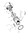
- the electric generator consists of a stator (5) that is mounted in a fixed position inside the casing of the body (1) and a free-rotating rotor (6) mounted within said stator (5), with said rotor (6) mounted on a shaft (7) that is attached to the hub (3) upon which the blades (4) are attached.
- the hub (3) is prolonged in the rear by an extension that constitutes the shaft (7), whereby both elements are constructed as a single piece, which is contemplated to be of boiler steel, which facilitates its manufacture and assembly, as there are no joint couplings between these two components.
- That single piece assembly of the hub (3) and the shaft (7) provides a large inner space, which may be accessed by operators (8) for performing those operations that may be required inside, with incorporation on the rear part of a cover (9), which is an integral part of the same and joined to the end of the shaft (7), providing reinforcement for the same, whilst upon said cover (9) a boss (10) is mounted by axial attachment to the outer part, with respect to which the manifold (11) of the electric generator is mounted.
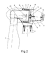
- Said unit is assembled to the body (1) of the wind turbine (see Figure 2) by means of two bearings (12 and 13), one of which (12) is mounted on the boss (10) and by means of this, attachment is made onto a support (14) that is joined to the casing of the body (1); whilst the other bearing (13) is mounted on the actual shaft (7) on its forward part, between said shaft (7) and the casing of the body (1).
- an access window (18) is anticipated, whilst on the rear end a fan (19) may be mounted for cooling purposes.
- the blades (4) are attached in a rotary assembly on the hub (3), for the yaw of the same to the most suitable position, according to the power of the wind, for the purpose of achieving the optimum performance of the wind turbine in electrical power production and to avoid, when appropriate, deterioration caused by excessive stress in the case of extreme gusts of wind.
Abstract
Description
- The present invention refers to wind turbines used to produce electrical energy by harnessing the force of the wind, with provision of an anticipated structural arrangement that improves the features of construction, erection and operation of the wind turbine.
- The environmentally-friendly nature that defines wind energy, in addition to the progress that has been achieved in technological terms, leads wind energy to be increasingly used as a drive means for producing electricity, through the use of the so-called wind turbines.
- Said wind turbines generally consist of a blade rotor, by means of which the power of the wind is used to effect a rotary action that operates a generator for producing electricity.
- In wind turbines currently in use, the blade rotor consists of a core or hub, with respect to which the blades for harnessing the action of the wind are radially mounted; axially attached to said hub there is a shaft upon which the rotor of the generator producing the electricity is mounted, in a manner that said shaft is fitted axially in rotary assembly with respect to the body of the wind turbine, in which the stator of the electric generator is mounted in a fixed position, whilst the rotary arrangement of the shaft is established by means of a coupling using bearings.
- This structural design of the wind turbines implies considerable difficulties in the erection, given the components of the installation and the couplings that have to be effected between them, rendering them susceptible to noise, vibration and resonance during operation.
- The blades harnessing the action of the wind rotate on the hub, in order to yaw the positioning of the same in response to the power of the wind, using for this electric drive motors associated with the individual blades; this requires an expensive assembly and, furthermore, a possible electrical power supply failure renders inoperable the yaw rotation of the blades, making it necessary to provide emergency batteries or accumulators, given that said rotary drive for the yaw of the blades must always be operational to avoid deterioration in the event of strong gusts of wind and to exert a suitable control that will permit achieving the best performance from the wind turbine at each moment.
- In accordance with the invention, a wind turbine is proposed that is fitted with a number of improvements that permit a significantly enhanced design with regard to those features described above.
- The wind turbine covered by this invention consists of a blade rotor that comprises a hub that is prolonged at the rear with an extension that constitutes the shaft upon which the rotor of the electric generator is mounted, in a manner whereby the shaft and the hub structurally conform a single piece, to which the blades for harnessing the action of the wind are attached, in addition to the assembly of the rotary coupling with regard to the body of the wind turbine.
- The single piece of the shaft-hub is closed at the rear by means of a cover that is fitted as an integral part of the same, upon which and axially attached to the outer part there is a boss, with respect to which the manifold of the electric generator is mounted, in addition to a coupling bearing on a mount attached to the casing of the body of the wind turbine; a bearing which is coupled directly to the casing of the body of the wind turbine is attached on the forward area of the part of the single piece that constitutes the shaft.
- This thus provides a simple construction structure, as the hub unit of the blade rotor and the shaft of the rotary assembly only require the manufacture of a single piece, which is contemplated in boiler steel, with no need to perform any kind of coupling assembly between said parts; furthermore, the single piece unit of this assembly facilitates the erection of the wind turbine.
- It is contemplated that the assembly will be performed by means of elastomeric runners between the part that constitutes the shaft and the casing of the body of the wind turbine, whereby a rotary assembly is achieved that absorbs vibrations and avoids resonance.
- With regard to the assembly of the blades for harnessing the action of the wind, which are fitted for rotation on the hub, hydraulic drive cylinders are provided, by means of which each blade can be rotated individually, in order to adjust the positioning of the same in response to the power of the wind.
- This means a very straightforward installation, given that no motors are used, nor the corresponding necessary transmission, for said yaw function of the blades of the wind turbine; rather, said function is addressed using hydraulic cylinders, which are much easier to assemble and furthermore permit greater accuracy in the yaw movement of the blades, as no coupling transmissions are required.
- In addition, this arrangement of hydraulic cylinders removes the need for providing emergency electrical accumulators to cater for the possibility of failure in the electrical power supply, with only hydraulic accumulators required, which are of much lower cost and more reliable.
- It is necessary to provide a small battery for operating the servovalve for each cylinder; but this battery is very small, simple and of minimal cost compared to the electrical accumulators required for feeding the electric motors that operate the blades in traditional designs, in the event of a failure in the power supply.
- In view of all the above, the aforementioned wind turbine covered by the invention certainly provides highly advantageous characteristics, standing apart with distinct features with regard to those wind turbines that are currently known.
- Figure 1 provides a perspective drawing of the shaft-hub of the wind turbine in question, in an exploded view of the assembly in relation to the body of the wind turbine, with two blades partially displayed facing their respective assembly couplings.
- Figure 2 is a lateral cross-section view of the body of the assembled wind turbine.
- Figure 3 is a frontal cross-section view of the blade rotor of the wind turbine.
- Figure 4 is a frontal cross-section view of the body of the wind turbine.
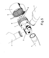
- Figure 5 is an exploded view of the wind turbine body and blade rotor assembly, in a embodiment for the rotary assembly by means of elastomeric runners.
- Figure 6 is a lateral cross-section view of the mounted assembly of the wind turbine, according to the embodiment of the previous figure.
-
- The invention refers to a wind turbine used for producing electrical energy through the power of the wind, consisting of a body (1) in which the operational assembly is installed, which is mounted on a supporting mast or tower (2) with the possibility for rotary yaw for alignment with the wind.
- A wind rotor is mounted in rotary assembly with regard to the body (1), consisting of a hub (3) upon which various blades (4) are attached for the purpose of harnessing the action of the wind, so that by means of the aforementioned blades (4) the wind rotates the hub (3), which transmits the rotary action to produce electricity by means of a generator that is installed in the body (1).
- The electric generator consists of a stator (5) that is mounted in a fixed position inside the casing of the body (1) and a free-rotating rotor (6) mounted within said stator (5), with said rotor (6) mounted on a shaft (7) that is attached to the hub (3) upon which the blades (4) are attached.
- According to the invention, the hub (3) is prolonged in the rear by an extension that constitutes the shaft (7), whereby both elements are constructed as a single piece, which is contemplated to be of boiler steel, which facilitates its manufacture and assembly, as there are no joint couplings between these two components.
- That single piece assembly of the hub (3) and the shaft (7) provides a large inner space, which may be accessed by operators (8) for performing those operations that may be required inside, with incorporation on the rear part of a cover (9), which is an integral part of the same and joined to the end of the shaft (7), providing reinforcement for the same, whilst upon said cover (9) a boss (10) is mounted by axial attachment to the outer part, with respect to which the manifold (11) of the electric generator is mounted.
- Said unit is assembled to the body (1) of the wind turbine (see Figure 2) by means of two bearings (12 and 13), one of which (12) is mounted on the boss (10) and by means of this, attachment is made onto a support (14) that is joined to the casing of the body (1); whilst the other bearing (13) is mounted on the actual shaft (7) on its forward part, between said shaft (7) and the casing of the body (1).
- Under the same concept of integration of the hub (3) and the shaft (7) within a single piece assembly, which is the essence of the invention, it is contemplated to mount the rotary assembly with regard to the body (1) of the wind turbine by means of elastomeric runners (Figures 5 and 6), in other words, by means of elastomeric runners (15) mounted inside the casing of the body (1), which provide roller support on the external face of the shaft (7) and other elastomeric runners that support on rolling tracks in a perpendicular arrangement to the former, determining between the assembly of the rollers (15 and 16) a radial and axial fastening of the assembly, with free rotation and with a set of rollers that absorb vibrations.
- On the rear casing (17) for closure of the body (1), an access window (18) is anticipated, whilst on the rear end a fan (19) may be mounted for cooling purposes.
- The blades (4) are attached in a rotary assembly on the hub (3), for the yaw of the same to the most suitable position, according to the power of the wind, for the purpose of achieving the optimum performance of the wind turbine in electrical power production and to avoid, when appropriate, deterioration caused by excessive stress in the case of extreme gusts of wind.
- To operate the drive for the yaw rotation of the blades (4) accordingly, attachment is made in relation to them, pursuant to this invention, of respective hydraulic drive cylinders (20), which are fitted inside the hub (3), by means of which, in relation to a corresponding hydraulic feed supply, the rotary operation of the blades (4) is performed, which is extremely accurate, as it acts directly on the blades (4), without intermediate transmissions, with provision of separate hydraulic accumulators for the operation of each one of the blades (4), whilst in order to ensure emergency operation whenever there is a failure in the power supply, regarding the servovalves for the control of the hydraulic cylinders (20), small batteries are provided that are of low cost and simple installation.
Claims (5)
- Improvements to wind turbines for electrical power production, of those consisting of a blade (4) rotor for harnessing the action of the wind, said rotor being mounted in a rotary arrangement with respect to the body (1) of the wind turbine in which inclusion is made of an electric generator driven by the rotary action of the aforementioned blade rotor, characterised in that the rotor bearing the blades (4) consists of a hub (3) that is prolonged at the rear with an extension (7) that constitutes the assembly shaft with respect to the body (1) of the wind turbine, with the aforementioned hub (3) and the shaft (7) forming a single manufactured piece assembly.
- Improvements to wind turbines for electrical power production, all in accordance with claim 1, characterised in that the single piece assembly of the hub (3) and the shaft (7) configure a large space inside, with the rear attachment of a cover (9) that is an integral part of the end of the shaft (7) and upon which, and in axial attachment on the outer part, a boss (10) is mounted, with respect to which the manifold of the electric generator is mounted.
- Improvements to wind turbines for electrical power production, all in accordance with claims 1 and 2, characterised in that the rotary assembly of the single piece unit of the hub (3) and the shaft (7) is attached to the body (1) of the wind turbine by means of a back-end bearing (12) that is fitted between the boss (10) of the cover (9) and a support (14) attached to the casing of the body (1), and to the forward part between the actual shaft (7) and the casing of the body (1) by means of a front-end bearing (13).
- Improvements to wind turbines for electrical power production, all in accordance with claim 1, characterised in that in one embodiment the assembly of the single piece unit of the hub (3) and the shaft (7), with respect to the body (1) of the wind turbine, is attached by means of elastomeric runners (15 and 16), which are mounted between the shaft (7) and the casing of the body (1), providing roller support in the radial direction and in the axial direction of the assembly.
- Improvements to wind turbines for electrical power production, all in accordance with claim 1, characterised in that the blades (4) are mounted in a rotary assembly on the hub (3), with attachment made in relation to them of respective separate hydraulic drive cylinders (20) by means of which the blades (4) turn to adjust their yaw in response to the strength of the wind.
Applications Claiming Priority (2)
| Application Number | Priority Date | Filing Date | Title |
|---|---|---|---|
| ES200201362A ES2206028B1 (en) | 2002-06-13 | 2002-06-13 | PERFECTION IN THE ELECTRICAL PRODUCTION AIRCRAFTERS. |
| ES200201362 | 2002-06-13 |
Publications (2)
| Publication Number | Publication Date |
|---|---|
| EP1371845A2 true EP1371845A2 (en) | 2003-12-17 |
| EP1371845A3 EP1371845A3 (en) | 2008-09-03 |
Family
ID=29558521
Family Applications (1)
| Application Number | Title | Priority Date | Filing Date |
|---|---|---|---|
| EP03291422A Withdrawn EP1371845A3 (en) | 2002-06-13 | 2003-06-13 | Wind turbine hub |
Country Status (3)
| Country | Link |
|---|---|
| US (1) | US6759758B2 (en) |
| EP (1) | EP1371845A3 (en) |
| ES (1) | ES2206028B1 (en) |
Cited By (10)
| Publication number | Priority date | Publication date | Assignee | Title |
|---|---|---|---|---|
| WO2005103489A2 (en) * | 2004-04-19 | 2005-11-03 | Northern Power Systems, Inc. | Direct drive wind turbine |
| EP1884659A2 (en) * | 2006-07-31 | 2008-02-06 | General Electric Company | Ventilation assembly for wind turbine rotor hub |
| ES2323605A1 (en) * | 2005-01-07 | 2009-07-21 | General Electric Company | Method and apparatus for wind turbine air gap control |
| CN101737251A (en) * | 2008-11-21 | 2010-06-16 | 通用电气公司 | Spinner-less hub access and lifting system for a wind turbine |
| US7891941B2 (en) | 2003-05-30 | 2011-02-22 | Northern Power Systems, Inc. | Wind turbine having a direct-drive drivetrain |
| WO2012059516A3 (en) * | 2010-11-04 | 2012-06-28 | Wobben, Aloys | Door lock |
| EP2273104A3 (en) * | 2009-06-30 | 2012-08-01 | Vestas Wind Systems A/S | A wind turbine with improved yaw control |
| WO2012120485A2 (en) * | 2011-03-10 | 2012-09-13 | Wilic S.Ar.L. | Fluid-cooled wind turbine |
| WO2013037949A1 (en) * | 2011-09-16 | 2013-03-21 | Aktiebolaget Skf | Bearing and wind turbine |
| EP3242013A1 (en) | 2016-05-04 | 2017-11-08 | Nordex Energy GmbH | Wind power plant with an apparatus for rotating a nacelle of the wind power plant and method for mounting a device for rotating a nacelle |
Families Citing this family (43)
| Publication number | Priority date | Publication date | Assignee | Title |
|---|---|---|---|---|
| DE10119427A1 (en) * | 2001-04-20 | 2002-10-24 | Enron Wind Gmbh | Coupling device for a wind turbine |
| ITBZ20010043A1 (en) * | 2001-09-13 | 2003-03-13 | High Technology Invest Bv | ELECTRIC GENERATOR OPERATED BY WIND ENERGY. |
| DE10153683C1 (en) * | 2001-10-31 | 2003-05-22 | Aerodyn Eng Gmbh | Rotor shaft / hub unit for a wind turbine |
| ITMI20021439A1 (en) * | 2002-06-28 | 2003-12-29 | High Technology Invest Bv | HIGH ENERGY EFFICIENCY WIND GENERATION PLANT |
| DE10231948A1 (en) * | 2002-07-15 | 2004-01-29 | Ge Wind Energy Gmbh | Wind turbine and bearing arrangement therefor |
| DE102004005179B4 (en) * | 2004-02-02 | 2006-07-13 | Wobben, Aloys, Dipl.-Ing. | Wind turbine |
| ITBZ20040047A1 (en) | 2004-09-20 | 2004-12-20 | High Technology Invest Bv | ELECTRIC GENERATOR / MOTOR, IN PARTICULAR FOR USE IN WIND PLANTS, ROPE OR HYDRAULIC PLANTS. |
| DE102004046700B4 (en) * | 2004-09-24 | 2006-08-17 | Aloys Wobben | Wind turbine with a generator cooling |
| ITBZ20050062A1 (en) | 2005-11-29 | 2007-05-30 | High Technology Invest Bv | PERMANENT MAGNET ROTOR FOR GENERATORS AND ELECTRIC MOTORS |
| DE602006013011D1 (en) | 2005-09-21 | 2010-04-29 | High Technology Invest Bv | BEARING SEALING ASSEMBLY WITH LABYRINTH SEALING AND SCREW SEALING COMBINATION |
| ITBZ20050063A1 (en) | 2005-11-29 | 2007-05-30 | High Technology Invest Bv | LAMIERINI PACKAGE FOR GENERATORS AND ELECTRIC MOTORS AND PROCEDURE FOR ITS IMPLEMENTATION |
| KR100695012B1 (en) * | 2006-03-24 | 2007-03-14 | 유니슨 주식회사 | Wind turbine generator system |
| ES2308911B1 (en) * | 2006-12-05 | 2009-10-27 | GAMESA INNOVATION & TECHNOLOGY, S.L. | ELECTRICAL OPERATED VARIABLE PASSAGE CHANGE SYSTEM. |
| BRPI0622196A2 (en) * | 2006-12-22 | 2012-01-03 | High Technology Invest Bv | wind turbine with multiple generators |
| ITMI20081122A1 (en) | 2008-06-19 | 2009-12-20 | Rolic Invest Sarl | WIND GENERATOR PROVIDED WITH A COOLING SYSTEM |
| US8287421B2 (en) * | 2008-07-10 | 2012-10-16 | General Electric Company | Transmission and power generation system having torque reacting joint |
| US8298115B2 (en) * | 2008-07-10 | 2012-10-30 | General Electric Company | Wind turbine transmission assembly |
| US8365866B2 (en) * | 2008-07-10 | 2013-02-05 | General Electric Company | Internal lubrication for a gearbox, a power-generating wind turbine system, and a power-generating system |
| IT1390758B1 (en) | 2008-07-23 | 2011-09-23 | Rolic Invest Sarl | WIND GENERATOR |
| DE102008050848A1 (en) | 2008-10-08 | 2010-04-15 | Wobben, Aloys | ring generator |
| IT1391939B1 (en) | 2008-11-12 | 2012-02-02 | Rolic Invest Sarl | WIND GENERATOR |
| IT1391770B1 (en) | 2008-11-13 | 2012-01-27 | Rolic Invest Sarl | WIND GENERATOR FOR THE GENERATION OF ELECTRICITY |
| IT1392804B1 (en) | 2009-01-30 | 2012-03-23 | Rolic Invest Sarl | PACKAGING AND PACKAGING METHOD FOR POLE OF WIND GENERATORS |
| IT1393937B1 (en) | 2009-04-09 | 2012-05-17 | Rolic Invest Sarl | WIND TURBINE |
| IT1393707B1 (en) | 2009-04-29 | 2012-05-08 | Rolic Invest Sarl | WIND POWER PLANT FOR THE GENERATION OF ELECTRICITY |
| IT1394723B1 (en) | 2009-06-10 | 2012-07-13 | Rolic Invest Sarl | WIND POWER PLANT FOR THE GENERATION OF ELECTRICITY AND ITS CONTROL METHOD |
| IT1395148B1 (en) | 2009-08-07 | 2012-09-05 | Rolic Invest Sarl | METHOD AND APPARATUS FOR ACTIVATION OF AN ELECTRIC MACHINE AND ELECTRIC MACHINE |
| US20110121577A1 (en) * | 2009-11-20 | 2011-05-26 | Oscilla Power Inc. | Method and device for energy generation |
| IT1397081B1 (en) | 2009-11-23 | 2012-12-28 | Rolic Invest Sarl | WIND POWER PLANT FOR THE GENERATION OF ELECTRICITY |
| US9270150B2 (en) | 2009-12-16 | 2016-02-23 | Clear Path Energy, Llc | Axial gap rotating electrical machine |
| WO2011084530A2 (en) * | 2009-12-16 | 2011-07-14 | Clear Path Energy, Llc | Floating underwater support structure |
| IT1398060B1 (en) | 2010-02-04 | 2013-02-07 | Wilic Sarl | PLANT AND METHOD OF COOLING OF AN ELECTRIC GENERATOR OF AN AIR SPREADER, AND AIRCONDITIONER INCLUDING SUCH A COOLING PLANT |
| IT1399201B1 (en) | 2010-03-30 | 2013-04-11 | Wilic Sarl | AEROGENERATOR AND METHOD OF REMOVING A BEARING FROM A AIRCONDITIONER |
| IT1399511B1 (en) | 2010-04-22 | 2013-04-19 | Wilic Sarl | ELECTRIC GENERATOR FOR A VENTILATOR AND AEROGENER EQUIPPED WITH THIS ELECTRIC GENERATOR |
| WO2013042251A1 (en) | 2011-09-22 | 2013-03-28 | 三菱重工業株式会社 | Regenerated-energy power generation device and rotary wing attachment/detachment method therefor |
| ITMI20110378A1 (en) | 2011-03-10 | 2012-09-11 | Wilic Sarl | ROTARY ELECTRIC MACHINE FOR AEROGENERATOR |
| ITMI20110377A1 (en) | 2011-03-10 | 2012-09-11 | Wilic Sarl | ROTARY ELECTRIC MACHINE FOR AEROGENERATOR |
| ITMI20110375A1 (en) | 2011-03-10 | 2012-09-11 | Wilic Sarl | WIND TURBINE |
| JP5841662B2 (en) * | 2011-07-15 | 2016-01-13 | ツェットエフ ウィンド パワー アントワープ エヌ ヴイZf Wind Power Antwerpen N.V. | Nacelle mainframe structure and drivetrain assembly for wind turbine |
| EP3139033B1 (en) * | 2015-09-07 | 2019-02-20 | Siemens Aktiengesellschaft | Maintenance access to blade bearing of wind turbine |
| US10598159B2 (en) | 2016-05-06 | 2020-03-24 | General Electric Company | Wind turbine bearings |
| CN106321364A (en) * | 2016-11-08 | 2017-01-11 | 常州神力电机股份有限公司 | Wind driven generation unit with hub and generator outer rotor combined structure |
| CN106438206A (en) * | 2016-11-08 | 2017-02-22 | 常州神力电机股份有限公司 | Parallel type direct-driven wind power generator with hub and power generator outer rotor combined |
Citations (5)
| Publication number | Priority date | Publication date | Assignee | Title |
|---|---|---|---|---|
| US3815959A (en) * | 1972-08-08 | 1974-06-11 | M Hill | Industrial roller or wheel |
| GB2071779A (en) * | 1980-03-17 | 1981-09-23 | United Technologies Corp | Wind turbine blade pitch adjustment system |
| EP0864748A1 (en) * | 1997-03-10 | 1998-09-16 | Jeumont Industrie | Low speed gearless wind turbine |
| US6452287B1 (en) * | 1999-06-14 | 2002-09-17 | Ivan Looker | Windmill and method to use same to generate electricity, pumped air or rotational shaft energy |
| WO2003038275A1 (en) * | 2001-10-31 | 2003-05-08 | Aerodyn Engineering Gmbh | Shaft/hub unit for wind turbine rotor |
Family Cites Families (24)
| Publication number | Priority date | Publication date | Assignee | Title |
|---|---|---|---|---|
| US2177801A (en) * | 1937-02-04 | 1939-10-31 | Erren Rudolf Arnold | Electric generator |
| US3740565A (en) * | 1971-04-26 | 1973-06-19 | Adams B | Air driven modular tandem electrical generator |
| FR2487920A1 (en) * | 1980-07-29 | 1982-02-05 | Megatec Ind | ELECTRIC GENERATOR ACTIVATED BY THE WIND |
| NL8201283A (en) * | 1982-03-26 | 1983-10-17 | Fdo Techn Adviseurs | SHARABLE GONDOLA FOR A WINDMILL. |
| US5035575A (en) * | 1988-02-01 | 1991-07-30 | I.K. Trading Aps. | Yawing system for a wind mill |
| US4966525A (en) * | 1988-02-01 | 1990-10-30 | Erik Nielsen | Yawing device and method of controlling it |
| US5506453A (en) * | 1990-02-09 | 1996-04-09 | Mccombs; John C. | Machine for converting wind energy to electrical energy |
| JPH03241367A (en) * | 1990-02-20 | 1991-10-28 | Ricoh Co Ltd | Optical writing method |
| DE29609794U1 (en) * | 1996-06-03 | 1996-08-22 | Aerodyn Gmbh | Gear-generator combination |
| DE29612720U1 (en) * | 1996-07-23 | 1996-10-02 | Aerodyn Gmbh | Wind turbine |
| ES2144363B1 (en) * | 1998-03-26 | 2001-02-01 | Torres Martinez M | PERFECTION IN ELECTRICITY PRODUCING AIRBRUSHERS. |
| DE19916453A1 (en) * | 1999-04-12 | 2000-10-19 | Flender A F & Co | Wind turbine |
| AU4571599A (en) * | 1999-06-16 | 2001-01-02 | Prime Energy Corporation | Power-transducer/conversion system and related methodology |
| ES2157836B1 (en) * | 1999-10-18 | 2002-02-01 | Torres Martinez M | MULTIPOLAR AEROGENERATOR. |
| ES2163362B1 (en) * | 1999-11-29 | 2003-04-01 | Ecotecnia Societat Cooperativa | AEROGENERATOR |
| EP1126163A1 (en) * | 2000-02-16 | 2001-08-22 | Turbowinds N.V./S.A. | Blade pitch angle control device for wind turbine |
| ES2161196B1 (en) | 2000-05-09 | 2002-05-16 | Torres Disenos Ind S A M | INSTALLATION OF PARARRAYOS FOR AEROGENERATORS. |
| US6608397B2 (en) * | 2000-11-09 | 2003-08-19 | Ntn Corporation | Wind driven electrical power generating apparatus |
| US6465902B1 (en) * | 2001-04-18 | 2002-10-15 | The United States Of America As Represented By The Secretary Of The Navy | Controllable camber windmill blades |
| DE10119429A1 (en) * | 2001-04-20 | 2002-10-24 | Enron Wind Gmbh | Wind turbine with sliding container |
| DE10119428A1 (en) * | 2001-04-20 | 2002-10-24 | Enron Wind Gmbh | Base frame for arranging the shaft of the rotor of a wind turbine on its tower |
| DE10119427A1 (en) | 2001-04-20 | 2002-10-24 | Enron Wind Gmbh | Coupling device for a wind turbine |
| DE20114647U1 (en) * | 2001-07-17 | 2002-01-03 | Schlemenat Alfred | Wind turbine |
| ES2206014B1 (en) | 2002-03-26 | 2005-07-16 | Manuel Torres Martinez | CRANE FOR ASSEMBLY OF AIRBRUSHERS AND ASSEMBLY PROCESS. |
-
2002
- 2002-06-13 ES ES200201362A patent/ES2206028B1/en not_active Expired - Fee Related
-
2003
- 2003-05-26 US US10/445,432 patent/US6759758B2/en not_active Expired - Fee Related
- 2003-06-13 EP EP03291422A patent/EP1371845A3/en not_active Withdrawn
Patent Citations (5)
| Publication number | Priority date | Publication date | Assignee | Title |
|---|---|---|---|---|
| US3815959A (en) * | 1972-08-08 | 1974-06-11 | M Hill | Industrial roller or wheel |
| GB2071779A (en) * | 1980-03-17 | 1981-09-23 | United Technologies Corp | Wind turbine blade pitch adjustment system |
| EP0864748A1 (en) * | 1997-03-10 | 1998-09-16 | Jeumont Industrie | Low speed gearless wind turbine |
| US6452287B1 (en) * | 1999-06-14 | 2002-09-17 | Ivan Looker | Windmill and method to use same to generate electricity, pumped air or rotational shaft energy |
| WO2003038275A1 (en) * | 2001-10-31 | 2003-05-08 | Aerodyn Engineering Gmbh | Shaft/hub unit for wind turbine rotor |
Cited By (25)
| Publication number | Priority date | Publication date | Assignee | Title |
|---|---|---|---|---|
| US8454309B2 (en) | 2003-05-30 | 2013-06-04 | Northern Power Systems Utility Scale, Inc. | Wind turbine/generator set and method of making same |
| US8308430B2 (en) | 2003-05-30 | 2012-11-13 | Northern Power Systems Utility Scale, Inc. | Wind turbine/generator set having a stator cooling system located between stator frame and active coils |
| US7891941B2 (en) | 2003-05-30 | 2011-02-22 | Northern Power Systems, Inc. | Wind turbine having a direct-drive drivetrain |
| WO2005103489A2 (en) * | 2004-04-19 | 2005-11-03 | Northern Power Systems, Inc. | Direct drive wind turbine |
| US7075192B2 (en) | 2004-04-19 | 2006-07-11 | Northern Power Systems, Inc. | Direct drive wind turbine |
| US7109600B1 (en) | 2004-04-19 | 2006-09-19 | Northern Power Systems, Inc. | Direct drive wind turbine |
| US7119453B2 (en) | 2004-04-19 | 2006-10-10 | Northern Power Systems, Inc. | Direct drive wind turbine |
| US7183665B2 (en) | 2004-04-19 | 2007-02-27 | Northern Power Systems, Inc. | Direct drive wind turbine |
| WO2005103489A3 (en) * | 2004-04-19 | 2009-02-26 | Northern Power Systems Inc | Direct drive wind turbine |
| CN101427023B (en) * | 2004-04-19 | 2012-09-26 | 北方动力系统效用公司 | Direct drive wind turbine |
| ES2323605A1 (en) * | 2005-01-07 | 2009-07-21 | General Electric Company | Method and apparatus for wind turbine air gap control |
| EP1884659A2 (en) * | 2006-07-31 | 2008-02-06 | General Electric Company | Ventilation assembly for wind turbine rotor hub |
| EP1884659A3 (en) * | 2006-07-31 | 2012-11-07 | General Electric Company | Ventilation assembly for wind turbine rotor hub |
| CN101737251A (en) * | 2008-11-21 | 2010-06-16 | 通用电气公司 | Spinner-less hub access and lifting system for a wind turbine |
| CN101737251B (en) * | 2008-11-21 | 2014-03-05 | 通用电气公司 | Spinner-less hub access and lifting system for wind turbine |
| EP2273104A3 (en) * | 2009-06-30 | 2012-08-01 | Vestas Wind Systems A/S | A wind turbine with improved yaw control |
| US8643207B2 (en) | 2009-06-30 | 2014-02-04 | Vestas Wind Systems A/S | Wind turbine with improved yaw control |
| WO2012059516A3 (en) * | 2010-11-04 | 2012-06-28 | Wobben, Aloys | Door lock |
| EP2556285B1 (en) | 2010-11-04 | 2016-04-27 | Wobben Properties GmbH | Door lock |
| US9157577B2 (en) | 2010-11-04 | 2015-10-13 | Wobben Properties Gmbh | Door lock |
| WO2012120485A2 (en) * | 2011-03-10 | 2012-09-13 | Wilic S.Ar.L. | Fluid-cooled wind turbine |
| WO2012120485A3 (en) * | 2011-03-10 | 2013-06-06 | Wilic S.Ar.L. | Fluid-cooled wind turbine |
| US9209665B2 (en) | 2011-03-10 | 2015-12-08 | Windfin B.V. | Fluid-cooled wind turbine |
| WO2013037949A1 (en) * | 2011-09-16 | 2013-03-21 | Aktiebolaget Skf | Bearing and wind turbine |
| EP3242013A1 (en) | 2016-05-04 | 2017-11-08 | Nordex Energy GmbH | Wind power plant with an apparatus for rotating a nacelle of the wind power plant and method for mounting a device for rotating a nacelle |
Also Published As
| Publication number | Publication date |
|---|---|
| US20030230899A1 (en) | 2003-12-18 |
| ES2206028B1 (en) | 2005-03-01 |
| US6759758B2 (en) | 2004-07-06 |
| EP1371845A3 (en) | 2008-09-03 |
| ES2206028A1 (en) | 2004-05-01 |
Similar Documents
| Publication | Publication Date | Title |
|---|---|---|
| US6759758B2 (en) | Wind turbines for electrical power generation | |
| US7547985B2 (en) | Wind turbine apparatus | |
| JP4050441B2 (en) | Wind power generator | |
| EP2143944B1 (en) | Wind turbine | |
| EP2143941B1 (en) | Direct drive generator and wind turbine | |
| EP1999839B1 (en) | Wind turbine | |
| US8084879B2 (en) | Wind turbine | |
| EP2143942B1 (en) | Wind turbine | |
| JP5107353B2 (en) | Blade pitch angle control device and wind power generator | |
| EP2802769B1 (en) | Wind turbine rotor | |
| WO2015128426A1 (en) | Pitch bearing arrangement for a wind turbine installation | |
| EP2604857B1 (en) | A modular gear unit for a wind turbine | |
| EP2593674B1 (en) | Wind turbine | |
| US10508642B2 (en) | Rotor blade pitch arrangement | |
| US9447777B2 (en) | Continuous-flow power installation | |
| EP3130802B1 (en) | Reinforced main bearing of a wind turbine | |
| JPH0835482A (en) | Variable pitch mechanism for windmill | |
| KR200392171Y1 (en) | Double electric generating system directly coupled to wings of a windmill | |
| CN219932330U (en) | Wind generating set | |
| CN111622901A (en) | Direct drive wind turbine |
Legal Events
| Date | Code | Title | Description |
|---|---|---|---|
| PUAI | Public reference made under article 153(3) epc to a published international application that has entered the european phase |
Free format text: ORIGINAL CODE: 0009012 |
|
| AK | Designated contracting states |
Kind code of ref document: A2 Designated state(s): AT BE BG CH CY CZ DE DK EE ES FI FR GB GR HU IE IT LI LU MC NL PT RO SE SI SK TR |
|
| AX | Request for extension of the european patent |
Extension state: AL LT LV MK |
|
| PUAL | Search report despatched |
Free format text: ORIGINAL CODE: 0009013 |
|
| AK | Designated contracting states |
Kind code of ref document: A3 Designated state(s): AT BE BG CH CY CZ DE DK EE ES FI FR GB GR HU IE IT LI LU MC NL PT RO SE SI SK TR |
|
| AX | Request for extension of the european patent |
Extension state: AL LT LV MK |
|
| RIC1 | Information provided on ipc code assigned before grant |
Ipc: F16C 33/34 20060101ALI20080730BHEP Ipc: F03D 11/00 20060101ALI20080730BHEP Ipc: F03D 9/00 20060101ALI20080730BHEP Ipc: F03D 1/06 20060101AFI20030828BHEP |
|
| RAP1 | Party data changed (applicant data changed or rights of an application transferred) |
Owner name: M. TORRES DISENOS INDUSTRIALES, S.A.U. |
|
| RIN1 | Information on inventor provided before grant (corrected) |
Inventor name: TORRES MARTINEZ, MANUEL |
|
| AKX | Designation fees paid | ||
| REG | Reference to a national code |
Ref country code: DE Ref legal event code: 8566 |
|
| STAA | Information on the status of an ep patent application or granted ep patent |
Free format text: STATUS: THE APPLICATION IS DEEMED TO BE WITHDRAWN |
|
| 18D | Application deemed to be withdrawn |
Effective date: 20090304 |