EP1314885B1 - Flexible serrated trailing edge for wind turbine rotor blade - Google Patents
Flexible serrated trailing edge for wind turbine rotor blade Download PDFInfo
- Publication number
- EP1314885B1 EP1314885B1 EP02025882A EP02025882A EP1314885B1 EP 1314885 B1 EP1314885 B1 EP 1314885B1 EP 02025882 A EP02025882 A EP 02025882A EP 02025882 A EP02025882 A EP 02025882A EP 1314885 B1 EP1314885 B1 EP 1314885B1
- Authority
- EP
- European Patent Office
- Prior art keywords
- wind turbine
- turbine rotor
- trailing edge
- serrations
- blade
- Prior art date
- Legal status (The legal status is an assumption and is not a legal conclusion. Google has not performed a legal analysis and makes no representation as to the accuracy of the status listed.)
- Revoked
Links
- 238000000034 method Methods 0.000 claims abstract description 7
- 230000000737 periodic effect Effects 0.000 claims abstract description 4
- 230000004044 response Effects 0.000 claims abstract description 4
- 238000007373 indentation Methods 0.000 claims abstract description 3
- 230000006872 improvement Effects 0.000 abstract description 10
- 238000004519 manufacturing process Methods 0.000 abstract description 3
- 230000009467 reduction Effects 0.000 description 7
- 238000005259 measurement Methods 0.000 description 5
- 230000008901 benefit Effects 0.000 description 3
- 238000012986 modification Methods 0.000 description 3
- 230000004048 modification Effects 0.000 description 3
- 230000000694 effects Effects 0.000 description 2
- 238000011156 evaluation Methods 0.000 description 2
- 239000000463 material Substances 0.000 description 2
- 229920000515 polycarbonate Polymers 0.000 description 2
- 239000004417 polycarbonate Substances 0.000 description 2
- 241000238631 Hexapoda Species 0.000 description 1
- 239000002390 adhesive tape Substances 0.000 description 1
- 230000009286 beneficial effect Effects 0.000 description 1
- 238000010276 construction Methods 0.000 description 1
- 238000011109 contamination Methods 0.000 description 1
- 230000003203 everyday effect Effects 0.000 description 1
- 230000007704 transition Effects 0.000 description 1
Images


Classifications
-
- F—MECHANICAL ENGINEERING; LIGHTING; HEATING; WEAPONS; BLASTING
- F03—MACHINES OR ENGINES FOR LIQUIDS; WIND, SPRING, OR WEIGHT MOTORS; PRODUCING MECHANICAL POWER OR A REACTIVE PROPULSIVE THRUST, NOT OTHERWISE PROVIDED FOR
- F03D—WIND MOTORS
- F03D1/00—Wind motors with rotation axis substantially parallel to the air flow entering the rotor
- F03D1/06—Rotors
- F03D1/0608—Rotors characterised by their aerodynamic shape
- F03D1/0633—Rotors characterised by their aerodynamic shape of the blades
- F03D1/0641—Rotors characterised by their aerodynamic shape of the blades of the section profile of the blades, i.e. aerofoil profile
-
- F—MECHANICAL ENGINEERING; LIGHTING; HEATING; WEAPONS; BLASTING
- F03—MACHINES OR ENGINES FOR LIQUIDS; WIND, SPRING, OR WEIGHT MOTORS; PRODUCING MECHANICAL POWER OR A REACTIVE PROPULSIVE THRUST, NOT OTHERWISE PROVIDED FOR
- F03D—WIND MOTORS
- F03D80/00—Details, components or accessories not provided for in groups F03D1/00 - F03D17/00
-
- F—MECHANICAL ENGINEERING; LIGHTING; HEATING; WEAPONS; BLASTING
- F05—INDEXING SCHEMES RELATING TO ENGINES OR PUMPS IN VARIOUS SUBCLASSES OF CLASSES F01-F04
- F05B—INDEXING SCHEME RELATING TO WIND, SPRING, WEIGHT, INERTIA OR LIKE MOTORS, TO MACHINES OR ENGINES FOR LIQUIDS COVERED BY SUBCLASSES F03B, F03D AND F03G
- F05B2240/00—Components
- F05B2240/20—Rotors
- F05B2240/30—Characteristics of rotor blades, i.e. of any element transforming dynamic fluid energy to or from rotational energy and being attached to a rotor
- F05B2240/301—Cross-section characteristics
-
- F—MECHANICAL ENGINEERING; LIGHTING; HEATING; WEAPONS; BLASTING
- F05—INDEXING SCHEMES RELATING TO ENGINES OR PUMPS IN VARIOUS SUBCLASSES OF CLASSES F01-F04
- F05B—INDEXING SCHEME RELATING TO WIND, SPRING, WEIGHT, INERTIA OR LIKE MOTORS, TO MACHINES OR ENGINES FOR LIQUIDS COVERED BY SUBCLASSES F03B, F03D AND F03G
- F05B2240/00—Components
- F05B2240/20—Rotors
- F05B2240/30—Characteristics of rotor blades, i.e. of any element transforming dynamic fluid energy to or from rotational energy and being attached to a rotor
- F05B2240/31—Characteristics of rotor blades, i.e. of any element transforming dynamic fluid energy to or from rotational energy and being attached to a rotor of changeable form or shape
- F05B2240/311—Characteristics of rotor blades, i.e. of any element transforming dynamic fluid energy to or from rotational energy and being attached to a rotor of changeable form or shape flexible or elastic
-
- F—MECHANICAL ENGINEERING; LIGHTING; HEATING; WEAPONS; BLASTING
- F05—INDEXING SCHEMES RELATING TO ENGINES OR PUMPS IN VARIOUS SUBCLASSES OF CLASSES F01-F04
- F05B—INDEXING SCHEME RELATING TO WIND, SPRING, WEIGHT, INERTIA OR LIKE MOTORS, TO MACHINES OR ENGINES FOR LIQUIDS COVERED BY SUBCLASSES F03B, F03D AND F03G
- F05B2260/00—Function
- F05B2260/96—Preventing, counteracting or reducing vibration or noise
-
- Y—GENERAL TAGGING OF NEW TECHNOLOGICAL DEVELOPMENTS; GENERAL TAGGING OF CROSS-SECTIONAL TECHNOLOGIES SPANNING OVER SEVERAL SECTIONS OF THE IPC; TECHNICAL SUBJECTS COVERED BY FORMER USPC CROSS-REFERENCE ART COLLECTIONS [XRACs] AND DIGESTS
- Y02—TECHNOLOGIES OR APPLICATIONS FOR MITIGATION OR ADAPTATION AGAINST CLIMATE CHANGE
- Y02E—REDUCTION OF GREENHOUSE GAS [GHG] EMISSIONS, RELATED TO ENERGY GENERATION, TRANSMISSION OR DISTRIBUTION
- Y02E10/00—Energy generation through renewable energy sources
- Y02E10/70—Wind energy
- Y02E10/72—Wind turbines with rotation axis in wind direction
-
- Y—GENERAL TAGGING OF NEW TECHNOLOGICAL DEVELOPMENTS; GENERAL TAGGING OF CROSS-SECTIONAL TECHNOLOGIES SPANNING OVER SEVERAL SECTIONS OF THE IPC; TECHNICAL SUBJECTS COVERED BY FORMER USPC CROSS-REFERENCE ART COLLECTIONS [XRACs] AND DIGESTS
- Y02—TECHNOLOGIES OR APPLICATIONS FOR MITIGATION OR ADAPTATION AGAINST CLIMATE CHANGE
- Y02P—CLIMATE CHANGE MITIGATION TECHNOLOGIES IN THE PRODUCTION OR PROCESSING OF GOODS
- Y02P70/00—Climate change mitigation technologies in the production process for final industrial or consumer products
- Y02P70/50—Manufacturing or production processes characterised by the final manufactured product
-
- Y—GENERAL TAGGING OF NEW TECHNOLOGICAL DEVELOPMENTS; GENERAL TAGGING OF CROSS-SECTIONAL TECHNOLOGIES SPANNING OVER SEVERAL SECTIONS OF THE IPC; TECHNICAL SUBJECTS COVERED BY FORMER USPC CROSS-REFERENCE ART COLLECTIONS [XRACs] AND DIGESTS
- Y10—TECHNICAL SUBJECTS COVERED BY FORMER USPC
- Y10T—TECHNICAL SUBJECTS COVERED BY FORMER US CLASSIFICATION
- Y10T29/00—Metal working
- Y10T29/49—Method of mechanical manufacture
- Y10T29/49316—Impeller making
- Y10T29/49327—Axial blower or fan
-
- Y—GENERAL TAGGING OF NEW TECHNOLOGICAL DEVELOPMENTS; GENERAL TAGGING OF CROSS-SECTIONAL TECHNOLOGIES SPANNING OVER SEVERAL SECTIONS OF THE IPC; TECHNICAL SUBJECTS COVERED BY FORMER USPC CROSS-REFERENCE ART COLLECTIONS [XRACs] AND DIGESTS
- Y10—TECHNICAL SUBJECTS COVERED BY FORMER USPC
- Y10T—TECHNICAL SUBJECTS COVERED BY FORMER US CLASSIFICATION
- Y10T29/00—Metal working
- Y10T29/49—Method of mechanical manufacture
- Y10T29/49316—Impeller making
- Y10T29/49332—Propeller making
-
- Y—GENERAL TAGGING OF NEW TECHNOLOGICAL DEVELOPMENTS; GENERAL TAGGING OF CROSS-SECTIONAL TECHNOLOGIES SPANNING OVER SEVERAL SECTIONS OF THE IPC; TECHNICAL SUBJECTS COVERED BY FORMER USPC CROSS-REFERENCE ART COLLECTIONS [XRACs] AND DIGESTS
- Y10—TECHNICAL SUBJECTS COVERED BY FORMER USPC
- Y10T—TECHNICAL SUBJECTS COVERED BY FORMER US CLASSIFICATION
- Y10T29/00—Metal working
- Y10T29/49—Method of mechanical manufacture
- Y10T29/49316—Impeller making
- Y10T29/49336—Blade making
Definitions
- the present invention relates generally to the field of wind turbine aerodynamics, in particular to the optimizing of the energy output from a wind turbine rotor consisting of a plurality of blades.
- the aerodynamic surfaces of wind turbine blades have sharp or moderately blunt trailing edges from which the wake is shed.
- the shedding of the wake and the confluence of flow from the pressure and suction sides of the profile are sources of aerodynamic noise, and increased drag and reduced lift.
- the efficiency of the wind turbine rotor at a given wind speed is the ratio between the shaft power and the total mechanical power available in the wind at that wind speed.
- a power curve is a graph and/or a table of the electrical power output from the wind turbine as a function of the wind speed.
- a mechanical power curve is necessary, since the efficiency of the wind turbine rotor at a given wind speed is the ratio between the shaft power and the total mechanical power available.
- the measurement of a mechanical power curve is difficult, however, requiring stable torque instrumentation on the rotating shaft of the turbine. Consequently, the rotor efficiency is commonly evaluated on the basis of the electrical power, thereby inherently including the effects of the losses in gearbox, generator and cables. For blade efficiency evaluations in relative terms this is sufficiently accurate, provided the gearbox, generator and cable losses are known and are kept unchanged during any modifications of the wind turbine rotor.
- the efficiency of a wind turbine rotor is a function of the ratio between lift and drag on the aerodynamic profiles of the blade. A high lift/drag ratio is preferred.
- Certain aerodynamic profiles have shapes that provide lift/drag ratios above normal. These so-called laminar profiles are used e.g. on gliders that benefit from high lift/drag ratios. On wind turbines such profiles are not suitable, however, since they are very sensitive to surface contamination by e.g. insects or rain. Once contaminated their lift/drag ration drops to or below that of normal profiles.
- Lift modifying devices have been used on wind turbine blades to improve the lift/drag ratio or otherwise adjust the aerodynamic characteristics of the blade.
- Common devices include stall strips, vortex generators and Gurney flaps. Generally, such devices have negative effects on drag, and trade-offs between lift and drag are normally expected.
- Serrated trailing edges are known to improve the lift and drag characteristics of a lifting surface.
- Various embodiments are described in US Patent 5,088,665 .
- Serrated trailing edges are known to be used on wind turbines for noise reduction purposes. In such applications the serrations are usually limited to the outboard 10-20 percent of the span.
- An embodiment for noise reduction with hexagonal cross section of the serrations is described in US Patent 5,533 , 865 .
- An object of the present invention is to provide a method for the improvement of wind turbine rotor efficiency.
- Another object of the present invention is to provide embodiments for the improvement of wind turbine rotor efficiency.
- the efficiency of an existing wind turbine rotor is improved by the attachment of an apparatus to at least part of the trailing edge of the wind turbine blades, said apparatus being in the form of a serrated panel that is fixed to the surface of the blade and has the serrations extending into the airflow behind the trailing edge of the existing blade.
- the efficiency of a new wind turbine blade is improved by manufacturing the blade with serrations of at least part of the trailing edge of the wind turbine blade.
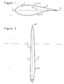
- Figure 1 shows a schematic cross section of a wind turbine blade 1 having a leading edge 2, a trailing edge 3, and a lifting surface 4 between the leading edge and the trailing edge.
- the lifting surface has a more convex side 5 referred to as the suction side, and a less convex side 6 referred to as the pressure side.
- a chord 7 is an imaginary line drawn between the leading edge 2 and the trailing edge 3.
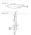
- Figure 2 shows a schematic plan view of a wind turbine blade 1 having a root end 8 and a tip end 9.
- the length of the blade from root to tip is referred to as a span.
- Parts of the blade near the tip are referred to as being outboard, and parts of the blade near the root are referred to as being inboard.
- the outboard part of the blade has an aerodynamically shaped cross-section, commonly with a profile belonging to one of numerous "families" of aerodynamic profiles used in the aeronautic industry.
- the aerodynamically shaped cross-section is commonly changed to a cylindrical cross-section at the root end.
- the transition from a profiled section to a circular section typically stretches from the radius of largest chord 10 to a point, normally referred to as the shoulder of the blade, to a point between the should and the root.
- FIG. 3 shows a schematic, cross-sectional view of a wind turbine blade 1 fitted with lift modifying devices commonly used on wind turbines. These devices comprise a stall strip 11 a vortex generator 12, and a Gurney flap 13. In most cases all of these types of lift modifying devices are not used simultaneously on any given section of the blade, but may be used on different sections.
- Figure 4 is a schematic, plan view of typical a wind turbine blade fitted with lift modifying devices commonly used on wind turbines. Typical spanwise locations of stall strips 11, vortex generators 12 and Gurney flaps 13 are shown.
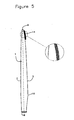
- Figure 5 is a schematic, plan view of a wind turbine blade fitted with serrated trailing edge as known applied for noise reduction purposes.
- the serrations 14 are triangular in shape, of hexagonal cross-section and having a fairly sharp vertex angle, typically less than 30 degrees.
- the serrated part of the trailing edge is limited to the outboard part of the blade near the tip, having a length of typically 10-20 percent of the span.
- FIG. 6 is a schematic, plan view of a wind turbine blade fitted with serrated trailing edge for efficiency improvement purposes in accordance with the present invention.
- the serrations 15 are here shown triangular in shape, of flat, rectangular or rounded cross-section and having a more blunt vertex angle than the serrations 14 for noise reduction, typically on the order of 60 degrees.
- the serrations may have other shapes, e.g. with rounded sides or other vertex angles than 60 degrees.
- the serrated part of the trailing edge is not limited to the outboard part of the blade near the tip, but has a length of typically 40-80 percent of the span.
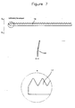
- Figure 7 shows a serration panel with some preferred dimensions of the serrations suitable for use on wind turbine blades of 20-50 m length.
- the serration panel 16 can be manufactured from a 1000 x 110 mm polycarbonate sheet.
- a serration tooth 17 can be an equilateral triangle with a height of 50 mm.
- the cross-section can be rectangular, with a thickness of 2 mm, and the panel can be bent along the long axis, the bend 18 having an angle of 15 degrees.
- Figure 8 is a schematic, cross-sectional view of the mounting of various preferred embodiments of the serrated panel on a wind turbine blade.
- a linear version of the panel 19 may be mounted on the pressure side 6 of the blade, projecting behind the trailing edge 3.
- a bent version of the panel 20 may also be mounted on the pressure side 6 of the blade, projecting behind the trailing edge 3, or a version 21 may be mounted on the suction side 5.
- the panel is manufactured in a material and thickness sufficient to ensure that the angle of the serrated part is generally unchanged irrespective of the speed and angle of the air flow at the trailing edge of the blade.
- Figure 9 is a schematic, cross-sectional view of the mounting of another preferred embodiment of the serrated panel on a wind turbine blade.
- the panel 22 is mounted on the pressure side 6 of the blade and is bent along its axis.
- the panel is manufactured in a material and thickness sufficient to ensure that the angle of the serrated part changes in response to the speed and angle of the air flow at the trailing edge of the blade.
- At a fairly low ambient wind speed giving a resulting wind speed vector 23 with a shallow angle to the chord 7 the shape of the panel is close to the shape when unloaded.
- the resulting wind speed vector 24 has a larger angle to the chord 7, and the panel flexes to a new position 25 or to any other position within a range defined by the combination of the stiffness characteristics of the serrated panel and the range of aerodynamic forces in the operating wind speed range of the wind turbine.
- Figure 10 is a plot of the measurement of the power performance of a 1.3 MW wind turbine with 62 m rotor diameter, fitted with standard lift modifying devices commonly used on wind turbines.
- Figure 11 is a plot of the measurement of the power performance of the same wind turbine as shown in figure 10 but fitted with serrated trailing edges in addition to the standard lift modifying devices.
- the serrated edges were furnished as a retrofit with serrated panels, each panel being manufactured from 2 mm polycarbonate, having a length of 1000 mm and a width of 107 mm, and having serrations in the form of saw teeth having a height of 50 mm and 60 degrees included angles between adjacent vertices.
- the panels were mounted with double-adhesive tapes on the pressure side of the blade with 75 mm of the panel width (of which 50 mm were serrations) extending behind the trailing edge of the existing blade, over a spanwise extent from 50 percent radius to 90 percent radius.
- the power curve has been shifted to the left at medium-high wind speeds, meaning that the annual energy output of the wind turbine has been improved.
- the improvement in annual energy output is about 4 percent. This improvement may lead to an increase in the annual energy production of about 150.000 kWh at a moderate wind site, corresponding to an increase in income of about $6000.
- the cost of the serrated trailing edge panels needed for this improvement in wind turbine efficiency is less that $100.
- the size, shape and flexibility of the serrations may be varied along the wingspan, and large or small portions of the wingspan may be left without serrations, all in order to maximise the improvement in the efficiency of the wind turbine rotor.
Abstract
Description
- The present invention relates generally to the field of wind turbine aerodynamics, in particular to the optimizing of the energy output from a wind turbine rotor consisting of a plurality of blades.
- Typically, the aerodynamic surfaces of wind turbine blades have sharp or moderately blunt trailing edges from which the wake is shed. The shedding of the wake and the confluence of flow from the pressure and suction sides of the profile are sources of aerodynamic noise, and increased drag and reduced lift.
- For a wind turbine rotor of a given diameter it is possible to determine the total mechanical power available at a given wind speed. The efficiency of the wind turbine rotor at a given wind speed is the ratio between the shaft power and the total mechanical power available in the wind at that wind speed.
- For everyday purposes the efficiency of a wind turbine rotor is displayed in the so-called power curve of the wind turbine. A power curve is a graph and/or a table of the electrical power output from the wind turbine as a function of the wind speed. For blade efficiency evaluations in absolute terms a mechanical power curve is necessary, since the efficiency of the wind turbine rotor at a given wind speed is the ratio between the shaft power and the total mechanical power available. The measurement of a mechanical power curve is difficult, however, requiring stable torque instrumentation on the rotating shaft of the turbine. Consequently, the rotor efficiency is commonly evaluated on the basis of the electrical power, thereby inherently including the effects of the losses in gearbox, generator and cables. For blade efficiency evaluations in relative terms this is sufficiently accurate, provided the gearbox, generator and cable losses are known and are kept unchanged during any modifications of the wind turbine rotor.
- For the wind speed range that contributes most of the annual energy output the efficiency of a wind turbine rotor is a function of the ratio between lift and drag on the aerodynamic profiles of the blade. A high lift/drag ratio is preferred.
- Certain aerodynamic profiles have shapes that provide lift/drag ratios above normal. These so-called laminar profiles are used e.g. on gliders that benefit from high lift/drag ratios. On wind turbines such profiles are not suitable, however, since they are very sensitive to surface contamination by e.g. insects or rain. Once contaminated their lift/drag ration drops to or below that of normal profiles.
- Lift modifying devices have been used on wind turbine blades to improve the lift/drag ratio or otherwise adjust the aerodynamic characteristics of the blade. Common devices include stall strips, vortex generators and Gurney flaps. Generally, such devices have negative effects on drag, and trade-offs between lift and drag are normally expected.
- Serrated trailing edges are known to improve the lift and drag characteristics of a lifting surface. Various embodiments are described in
US Patent 5,088,665 . - Serrated trailing edges are known to be used on wind turbines for noise reduction purposes. In such applications the serrations are usually limited to the outboard 10-20 percent of the span. An embodiment for noise reduction with hexagonal cross section of the serrations is described in
US Patent 5,533 ,865 . - A more general description of the use of serrated trailing edges on wind turbine blades with the purpose of noise reduction is presented in "Noise Reduction By Using Serrated Trailing Edges / K.A. Braun, N.v.d. Borg, T. Dassen, A.Gordner, R. Parchen", Proceedings of EWEC 97, Dublin 1997.
- None of the above descriptions or uses of serrated trailing edges have been shown to improve wind turbine rotor efficiency, or have been used to improve or attempt to improve wind turbine rotor efficiency.
- An object of the present invention is to provide a method for the improvement of wind turbine rotor efficiency.
- Another object of the present invention is to provide embodiments for the improvement of wind turbine rotor efficiency.
- These and other objects of the invention are met by providing the blades of a wind turbine rotor with serrated trailing edges each having a plurality of span-wise, periodic indentations, preferably in the form of saw teeth having approximately 60 degrees included angles between adjacent vertices and having the features according to
claim 6. - In one manifestation of the invention, the efficiency of an existing wind turbine rotor is improved by the attachment of an apparatus to at least part of the trailing edge of the wind turbine blades, said apparatus being in the form of a serrated panel that is fixed to the surface of the blade and has the serrations extending into the airflow behind the trailing edge of the existing blade.
- In another manifestation of the invention the efficiency of a new wind turbine blade is improved by manufacturing the blade with serrations of at least part of the trailing edge of the wind turbine blade.
- The invention will be more fully described hereinafter with reference to the accompanying drawings forming a part hereof, wherein like reference numerals refer to like parts throughout.
-
- Figure 1 is a schematic, cross-sectional view of an aerodynamic profile commonly used on wind turbines.
- Figure 2 is a schematic, plan view of a typical wind turbine blade.
- Figure 3 is a schematic, cross-sectional view of a wind turbine blade fitted with lift modifying devices commonly used on wind turbines.
- Figure 4 is a schematic, plan view of typical a wind turbine blade fitted with lift modifying devices commonly used on wind turbines.
- Figure 5 is a schematic, plan view of a wind turbine blade fitted with serrated trailing edge as known applied for noise reduction purposes;
- Figure 6 is a schematic, plan view of a wind turbine blade fitted with serrated trailing edge for efficiency improvement purposes in accordance with the present invention;
- Figure 7 is an enlargement of Figure 6, showing some preferred dimensions of one type of serrated panel;
- Figure 8 is a schematic, cross-sectional view of the mounting of a preferred embodiment of the serrated panel on a wind turbine blade;
- Figure 9 is another schematic, cross-sectional view of the mounting of another preferred embodiment of the serrated panel on a wind turbine blade.
- Figure 10 is a plot of the measurement of the power performance of a wind turbine fitted with standard lift modifying devices commonly used on wind turbines.
- Figure 11 is a plot of the measurement of the power performance of the same wind turbine as shown in figure 10 but fitted with serrated trailing edges in addition to the standard lift modifying devices.
- Figure 1 shows a schematic cross section of a
wind turbine blade 1 having a leadingedge 2, atrailing edge 3, and alifting surface 4 between the leading edge and the trailing edge. The lifting surface has a moreconvex side 5 referred to as the suction side, and a lessconvex side 6 referred to as the pressure side. Achord 7 is an imaginary line drawn between the leadingedge 2 and thetrailing edge 3. - Figure 2 shows a schematic plan view of a
wind turbine blade 1 having a root end 8 and atip end 9. The length of the blade from root to tip is referred to as a span. Parts of the blade near the tip are referred to as being outboard, and parts of the blade near the root are referred to as being inboard. The outboard part of the blade has an aerodynamically shaped cross-section, commonly with a profile belonging to one of numerous "families" of aerodynamic profiles used in the aeronautic industry. At the inboard part of the blade the aerodynamically shaped cross-section is commonly changed to a cylindrical cross-section at the root end. The transition from a profiled section to a circular section typically stretches from the radius oflargest chord 10 to a point, normally referred to as the shoulder of the blade, to a point between the should and the root. - Figure 3 shows a schematic, cross-sectional view of a
wind turbine blade 1 fitted with lift modifying devices commonly used on wind turbines. These devices comprise a stall strip 11 avortex generator 12, and a Gurneyflap 13. In most cases all of these types of lift modifying devices are not used simultaneously on any given section of the blade, but may be used on different sections. - Figure 4 is a schematic, plan view of typical a wind turbine blade fitted with lift modifying devices commonly used on wind turbines. Typical spanwise locations of
stall strips 11,vortex generators 12 and Gurneyflaps 13 are shown. - Figure 5 is a schematic, plan view of a wind turbine blade fitted with serrated trailing edge as known applied for noise reduction purposes. The
serrations 14 are triangular in shape, of hexagonal cross-section and having a fairly sharp vertex angle, typically less than 30 degrees. The serrated part of the trailing edge is limited to the outboard part of the blade near the tip, having a length of typically 10-20 percent of the span. - Figure 6 is a schematic, plan view of a wind turbine blade fitted with serrated trailing edge for efficiency improvement purposes in accordance with the present invention. The
serrations 15 are here shown triangular in shape, of flat, rectangular or rounded cross-section and having a more blunt vertex angle than theserrations 14 for noise reduction, typically on the order of 60 degrees. The serrations may have other shapes, e.g. with rounded sides or other vertex angles than 60 degrees. The serrated part of the trailing edge is not limited to the outboard part of the blade near the tip, but has a length of typically 40-80 percent of the span. - Figure 7 shows a serration panel with some preferred dimensions of the serrations suitable for use on wind turbine blades of 20-50 m length. The
serration panel 16 can be manufactured from a 1000 x 110 mm polycarbonate sheet. Aserration tooth 17 can be an equilateral triangle with a height of 50 mm. The cross-section can be rectangular, with a thickness of 2 mm, and the panel can be bent along the long axis, thebend 18 having an angle of 15 degrees. - Figure 8 is a schematic, cross-sectional view of the mounting of various preferred embodiments of the serrated panel on a wind turbine blade. A linear version of the
panel 19 may be mounted on thepressure side 6 of the blade, projecting behind the trailingedge 3. A bent version of thepanel 20 may also be mounted on thepressure side 6 of the blade, projecting behind the trailingedge 3, or aversion 21 may be mounted on thesuction side 5. The panel is manufactured in a material and thickness sufficient to ensure that the angle of the serrated part is generally unchanged irrespective of the speed and angle of the air flow at the trailing edge of the blade. - Figure 9 is a schematic, cross-sectional view of the mounting of another preferred embodiment of the serrated panel on a wind turbine blade. The
panel 22 is mounted on thepressure side 6 of the blade and is bent along its axis. The panel is manufactured in a material and thickness sufficient to ensure that the angle of the serrated part changes in response to the speed and angle of the air flow at the trailing edge of the blade. At a fairly low ambient wind speed giving a resultingwind speed vector 23 with a shallow angle to thechord 7 the shape of the panel is close to the shape when unloaded. At a higher ambient wind speed the resultingwind speed vector 24 has a larger angle to thechord 7, and the panel flexes to anew position 25 or to any other position within a range defined by the combination of the stiffness characteristics of the serrated panel and the range of aerodynamic forces in the operating wind speed range of the wind turbine. This means that by proper tuning of the stiffness characteristics of the serrated panel the aerodynamic properties of the serrated trailing edge may be automatically and instantaneously adjusted to the actual wind conditions in a manner that is particularly beneficial to the improvement of the efficiency of the wind turbine rotor. - Figure 10 is a plot of the measurement of the power performance of a 1.3 MW wind turbine with 62 m rotor diameter, fitted with standard lift modifying devices commonly used on wind turbines.
- Figure 11 is a plot of the measurement of the power performance of the same wind turbine as shown in figure 10 but fitted with serrated trailing edges in addition to the standard lift modifying devices. The serrated edges were furnished as a retrofit with serrated panels, each panel being manufactured from 2 mm polycarbonate, having a length of 1000 mm and a width of 107 mm, and having serrations in the form of saw teeth having a height of 50 mm and 60 degrees included angles between adjacent vertices. The panels were mounted with double-adhesive tapes on the pressure side of the blade with 75 mm of the panel width (of which 50 mm were serrations) extending behind the trailing edge of the existing blade, over a spanwise extent from 50 percent radius to 90 percent radius. As a result the power curve has been shifted to the left at medium-high wind speeds, meaning that the annual energy output of the wind turbine has been improved. In the present example the improvement in annual energy output is about 4 percent. This improvement may lead to an increase in the annual energy production of about 150.000 kWh at a moderate wind site, corresponding to an increase in income of about $6000. The cost of the serrated trailing edge panels needed for this improvement in wind turbine efficiency is less that $100.
In any of the embodiments described above the size, shape and flexibility of the serrations may be varied along the wingspan, and large or small portions of the wingspan may be left without serrations, all in order to maximise the improvement in the efficiency of the wind turbine rotor. - The many features and advantages of the present invention are apparent from the details of the specification, and thus, it is intended by the appended claims to cover all such features and advantages of the serrated panel which fall within the true spirit and scope of the invention. Further, since numerous modifications and changes will readily occur to those skilled in the art based upon the disclosure herein, it is not desired to limit the invention to the exact construction and operation illustrated and described. Accordingly, all suitable modifications and equivalents may be resorted to falling within the scope of the invention.
Claims (9)
- A method for improving the efficiency of a wind turbine rotor, comprising the furnishing a serrated panel at a trailing edge (3) on each of the wind turbine rotor blades (1) of the wind turbine rotor, each of said panels having a plurality of span-wise, periodic indentations (15), such that the serrations extend from the trailing edge into airflow behind the trailing edge on each wind turbine rotor blade of the wind turbine rotor, wherein the serrations are provided at an angle different from 0 degrees relative to the blade chord, characterized in that the angle of the serrated part changes passively in response to the speed and angle of the air flow at the trailing edge of the blade due to the flexing of the serrations and/or the serrated panel.
- A method for improving the efficiency of a wind turbine rotor according to claim 1, wherein the serrations (15) are provided as a retrofit of an existing wind turbine rotor by the attachment of a serrated panel to the surface of the wind turbine blade near the existing trailing edge and where the serrations extend from the existing trailing edge (3) of the blade into the airflow behind the existing trailing edge.
- A method for improving the efficiency of a wind turbine rotor according to claim 1, wherein the serrations (15) are provided as part of a new blade.
- A method for improving the efficiency of a wind turbine rotor according to any of the previous claims, wherein the serrations (15) are provided over a span wise extent of the trailing edge having a length of between 30 and 100 percent of the radius of the blade.
- A method for improving the efficiency of a wind turbine rotor according to any of the previous claims, wherein the serrations (15) are provided in the form of saw teeth having approximately 60 degrees included angles between adjacent vertices.
- An apparatus for improving the efficiency of a wind turbine rotor, comprising a serrated panel connected to each wind turbine rotor blade, an upper and a lower surface on each panel, a plurality of span-wise, periodic indentions (15) on each panel, means for connecting the serrated panel to a trailing edge (3) on each of the wind turbine rotor blades of the wind turbine rotor such that the serrated panel extends from the trailing edge into airflow behind the trailing edge on each wind turbine rotor blade of the wind turbine rotor, wherein the serrations on each wind turbine rotor blade having an angle different from 0 degrees relative to a mounting surface on each of the wind turbine rotor blades of the wind turbine rotor, characterized in that the serrations and each of the serrated panels have a given stiffness allowing for an angle of the serrations to change passively in response to speed and angle of the airflow at the trailing edge of each of the wind turbine rotor blades (1) due to flexing of the serrations (15) and the serrated panel.
- An apparatus for improving the efficiency of a wind turbine rotor according to claim 6, wherein the serrations (15) have a span wise extent of the trailing edge having a length of between 30 and 100 percent of the radius of the blade.
- An apparatus for improving the efficiency of a wind turbine rotor according to any of claims 6 or 7, wherein the serrations (15) have the form of saw teeth having approximately 60 degrees included angles between adjacent vertices.
- An apparatus for improving the efficiency of a wind turbine rotor according to any of claims 6-8, wherein the part of the serrated panel serrations (15) have the form of saw teeth having approximately 60 degrees included angles between adjacent vertices.
Applications Claiming Priority (2)
| Application Number | Priority Date | Filing Date | Title |
|---|---|---|---|
| US991781 | 2001-11-26 | ||
| US09/991,781 US7059833B2 (en) | 2001-11-26 | 2001-11-26 | Method for improvement of the efficiency of a wind turbine rotor |
Publications (2)
| Publication Number | Publication Date |
|---|---|
| EP1314885A1 EP1314885A1 (en) | 2003-05-28 |
| EP1314885B1 true EP1314885B1 (en) | 2007-08-29 |
Family
ID=25537555
Family Applications (1)
| Application Number | Title | Priority Date | Filing Date |
|---|---|---|---|
| EP02025882A Revoked EP1314885B1 (en) | 2001-11-26 | 2002-11-19 | Flexible serrated trailing edge for wind turbine rotor blade |
Country Status (6)
| Country | Link |
|---|---|
| US (1) | US7059833B2 (en) |
| EP (1) | EP1314885B1 (en) |
| AT (1) | ATE371812T1 (en) |
| DE (1) | DE60222079T2 (en) |
| DK (1) | DK1314885T3 (en) |
| ES (1) | ES2289043T3 (en) |
Cited By (13)
| Publication number | Priority date | Publication date | Assignee | Title |
|---|---|---|---|---|
| CN101618764A (en) * | 2008-05-27 | 2010-01-06 | 尤洛考普特德国有限公司 | Pneumatic airfoil with reversible deformation contour for aircrafts, especially gyroplane |
| WO2012019655A1 (en) | 2010-08-10 | 2012-02-16 | Siemens Aktiengesellschaft | Rotor blade element and method for improving the efficiency of a wind turbine rotor blade |
| WO2014086919A1 (en) | 2012-12-07 | 2014-06-12 | Wobben Properties Gmbh | Rotor blade trailing edge |
| DE102013202881A1 (en) * | 2013-02-21 | 2014-08-21 | Wobben Properties Gmbh | Method for determining dimensional profile geometry of to-be-produced trailing edge of rotor blade of aerodynamic rotor, involves calculating tooth height and width of blade based on data related to radial positions of blade profile |
| DE102013204637A1 (en) | 2013-03-15 | 2014-09-18 | Wobben Properties Gmbh | Wind turbine |
| EP2851554A1 (en) | 2013-09-18 | 2015-03-25 | Siemens Aktiengesellschaft | Arrangement to reduce noise emission |
| DE102014213930A1 (en) * | 2014-07-17 | 2016-01-21 | Wobben Properties Gmbh | Rotor blade tip trailing edge |
| US9567980B2 (en) | 2012-02-24 | 2017-02-14 | Siemens Aktiengesellschaft | Arrangement to reduce noise originated by a wind turbine blade |
| EP3176425A1 (en) | 2015-12-01 | 2017-06-07 | Stichting Nationaal Lucht- en Ruimtevaart Laboratorium | Assembly of aerofoil-shaped body and noise reducing serration and wind turbine provided therewith |
| US9945357B2 (en) | 2012-04-04 | 2018-04-17 | Siemens Aktiengesellschaft | Flexible flap arrangement for a wind turbine rotor blade |
| US10082129B2 (en) | 2012-12-07 | 2018-09-25 | Wobben Properties Gmbh | Wind turbine |
| US10900465B2 (en) | 2014-06-16 | 2021-01-26 | Brunel University London | Noise reduction to the trailing edge of fluid dynamic bodies |
| US10907610B2 (en) | 2014-07-17 | 2021-02-02 | Wobben Properties Gmbh | Wind-turbine rotor blade, rotor blade trailing edge, method for producing a wind-turbine rotor blade, and wind turbine |
Families Citing this family (134)
| Publication number | Priority date | Publication date | Assignee | Title |
|---|---|---|---|---|
| JP4504808B2 (en) | 2002-06-05 | 2010-07-14 | アロイス・ヴォベン | Wind power generator |
| DE10319246A1 (en) * | 2003-04-28 | 2004-12-16 | Aloys Wobben | Rotor blade of a wind turbine |
| DE10340978B4 (en) * | 2003-09-05 | 2008-09-18 | Moosdorf, Reinhard W. | Synthetic fiber element for rotor blades |
| FR2862941B1 (en) * | 2003-11-27 | 2007-02-23 | Airbus France | METHOD FOR AVOIDING THE VIBRATION OF A STEERING GOVERNANCE OF AN AIRCRAFT AND AIRCRAFT USING SAID METHOD |
| JP2005347797A (en) * | 2004-05-31 | 2005-12-15 | Orion Denki Kk | Reproducer or recorder/reproducer, or video display incorporating reproducer or recorder/reproducer |
| CN100392240C (en) * | 2004-12-20 | 2008-06-04 | 李锋 | Wing panels of blower fan of using wind energy to generate power |
| US20080232973A1 (en) * | 2005-07-21 | 2008-09-25 | Saint Louis University | Propeller blade |
| ES2318925B1 (en) * | 2005-09-22 | 2010-02-11 | GAMESA INNOVATION & TECHNOLOGY, S.L. | AEROGENERATOR WITH A BLADE ROTOR THAT REDUCES NOISE. |
| US7458777B2 (en) * | 2005-09-22 | 2008-12-02 | General Electric Company | Wind turbine rotor assembly and blade having acoustic flap |
| DK176352B1 (en) * | 2005-12-20 | 2007-09-10 | Lm Glasfiber As | Profile series for blade for wind turbines |
| NL1031223C1 (en) * | 2006-02-23 | 2007-08-24 | Stichting Nationaal Lucht En R | Wind turbine blade, has brush at back edge of blade, where brush includes synthetic bristles that rest parallel to top or bottom of blade |
| PT2007981T (en) | 2006-04-02 | 2021-02-11 | Wobben Properties Gmbh | Wind turbine with slender blade |
| EP1845258A1 (en) * | 2006-04-10 | 2007-10-17 | Siemens Aktiengesellschaft | Wind turbine rotor blade |
| ES2294927B1 (en) | 2006-05-31 | 2009-02-16 | Gamesa Eolica, S.A. | AIRLINER SHOVEL WITH DIVERGING OUTPUT EDGE. |
| US20080296906A1 (en) * | 2006-06-12 | 2008-12-04 | Daw Shien Scientific Research And Development, Inc. | Power generation system using wind turbines |
| US20090044535A1 (en) * | 2006-06-12 | 2009-02-19 | Daw Shien Scientific Research And Development, Inc. | Efficient vapor (steam) engine/pump in a closed system used at low temperatures as a better stirling heat engine/refrigerator |
| US20090211223A1 (en) * | 2008-02-22 | 2009-08-27 | James Shihfu Shiao | High efficient heat engine process using either water or liquefied gases for its working fluid at lower temperatures |
| US20090249779A1 (en) * | 2006-06-12 | 2009-10-08 | Daw Shien Scientific Research & Development, Inc. | Efficient vapor (steam) engine/pump in a closed system used at low temperatures as a better stirling heat engine/refrigerator |
| ES2310958B1 (en) * | 2006-09-15 | 2009-11-10 | GAMESA INNOVATION & TECHNOLOGY, S.L. | OPTIMIZED AEROGENERATOR SHOVEL. |
| US7617741B1 (en) | 2006-09-19 | 2009-11-17 | Robert Vanderhye | Wind turbine testing |
| KR100816851B1 (en) | 2006-12-22 | 2008-03-26 | 군산대학교산학협력단 | Turbine blade for wind power generation |
| US20080166241A1 (en) * | 2007-01-04 | 2008-07-10 | Stefan Herr | Wind turbine blade brush |
| EP1944505B1 (en) * | 2007-01-12 | 2012-11-28 | Siemens Aktiengesellschaft | Wind turbine rotor blade with vortex generators |
| US7918653B2 (en) * | 2007-02-07 | 2011-04-05 | General Electric Company | Rotor blade trailing edge assemby and method of use |
| EP1978245A1 (en) | 2007-04-04 | 2008-10-08 | Siemens Aktiengesellschaft | Optimised layout for wind turbine rotor blades |
| ES2345583B1 (en) | 2007-05-31 | 2011-07-28 | GAMESA INNOVATION & TECHNOLOGY, S.L. | AEROGENERATOR SHOVEL WITH ANTI-NOISE DEVICES. |
| ES2326203B1 (en) * | 2007-07-23 | 2010-07-09 | GAMESA INNOVATION & TECHNOLOGY, S.L. | AEROGENERATOR SHOVEL WITH ARCHABLE ALERONS. |
| EP2031242A1 (en) * | 2007-08-29 | 2009-03-04 | Lm Glasfiber A/S | A blade element for mounting on a wind turbine blade and a method of changing the aerodynamic profile of a wind turbine blade |
| EP2031243A1 (en) * | 2007-08-31 | 2009-03-04 | Lm Glasfiber A/S | Means to maintain a flow attached to the exterior of a flow control member |
| ES2326352B1 (en) * | 2007-09-14 | 2010-07-15 | GAMESA INNOVATION & TECHNOLOGY, S.L. | AEROGENERATOR SHOVEL WITH DEFLECTABLE ALERONS CONTROLLED BY CHANGES OF PRESSURE ON THE SURFACE. |
| US20090074585A1 (en) * | 2007-09-19 | 2009-03-19 | General Electric Company | Wind turbine blades with trailing edge serrations |
| US8197207B2 (en) * | 2007-12-31 | 2012-06-12 | General Electric Company | Individual blade noise measurement system and method for wind turbines |
| DK2078852T4 (en) | 2008-01-11 | 2022-07-04 | Siemens Gamesa Renewable Energy As | Rotor blade for a wind turbine |
| US7861583B2 (en) * | 2008-01-17 | 2011-01-04 | General Electric Company | Wind turbine anemometry compensation |
| ES2330500B1 (en) * | 2008-05-30 | 2010-09-13 | GAMESA INNOVATION & TECHNOLOGY, S.L. UNIPERSONAL | AEROGENERATOR SHOVEL WITH HYPERSUSTENTING ELEMENTS. |
| US8932024B2 (en) * | 2008-08-06 | 2015-01-13 | Mitsubishi Heavy Industries, Ltd. | Wind turbine blade and wind power generator using the same |
| US20100045037A1 (en) * | 2008-08-21 | 2010-02-25 | Daw Shien Scientific Research And Development, Inc. | Power generation system using wind turbines |
| US8096761B2 (en) * | 2008-10-16 | 2012-01-17 | General Electric Company | Blade pitch management method and system |
| EP2253836A1 (en) | 2009-05-18 | 2010-11-24 | Lm Glasfiber A/S | Wind turbine blade |
| EP2253837A1 (en) * | 2009-05-18 | 2010-11-24 | Lm Glasfiber A/S | Method of manufacturing a wind turbine blade having predesigned segment |
| EP2253838A1 (en) * | 2009-05-18 | 2010-11-24 | Lm Glasfiber A/S | A method of operating a wind turbine |
| EP2253839A1 (en) | 2009-05-18 | 2010-11-24 | Lm Glasfiber A/S | Wind turbine blade provided with flow altering devices |
| EP2253834A1 (en) * | 2009-05-18 | 2010-11-24 | Lm Glasfiber A/S | Wind turbine blade with base part having inherent non-ideal twist |
| GB2470589A (en) * | 2009-05-29 | 2010-12-01 | Vestas Wind Sys As | Branching spar wind turbine blade |
| US20110006165A1 (en) * | 2009-07-10 | 2011-01-13 | Peter Ireland | Application of conformal sub boundary layer vortex generators to a foil or aero/ hydrodynamic surface |
| US8328516B2 (en) * | 2009-09-29 | 2012-12-11 | General Electric Company | Systems and methods of assembling a rotor blade extension for use in a wind turbine |
| DK2343451T3 (en) | 2009-10-08 | 2018-07-23 | Lm Wind Power Int Tech Ii Aps | Wind turbine blade with a plurality of longitudinal flow controlling device parts |
| US8303250B2 (en) * | 2009-12-30 | 2012-11-06 | General Electric Company | Method and apparatus for increasing lift on wind turbine blade |
| US7909576B1 (en) | 2010-06-24 | 2011-03-22 | General Electric Company | Fastening device for rotor blade component |
| DE102010026588B4 (en) | 2010-07-08 | 2012-06-14 | Nordex Energy Gmbh | Wind turbine rotor blade with optimized trailing edge |
| US8083488B2 (en) * | 2010-08-23 | 2011-12-27 | General Electric Company | Blade extension for rotor blade in wind turbine |
| US7976276B2 (en) * | 2010-11-04 | 2011-07-12 | General Electric Company | Noise reducer for rotor blade in wind turbine |
| US7976283B2 (en) * | 2010-11-10 | 2011-07-12 | General Electric Company | Noise reducer for rotor blade in wind turbine |
| US8523515B2 (en) * | 2010-11-15 | 2013-09-03 | General Electric Company | Noise reducer for rotor blade in wind turbine |
| US8746053B2 (en) | 2010-12-16 | 2014-06-10 | Inventus Holdings, Llc | Method for determining optimum vortex generator placement for maximum efficiency on a retrofitted wind turbine generator of unknown aerodynamic design |
| US8267657B2 (en) * | 2010-12-16 | 2012-09-18 | General Electric Company | Noise reducer for rotor blade in wind turbine |
| EP2508750B1 (en) * | 2011-04-04 | 2015-06-17 | Siemens Aktiengesellschaft | Method of optimising a wind park construction |
| EP2514961B1 (en) * | 2011-04-19 | 2017-09-13 | Siemens Aktiengesellschaft | Spoiler for a wind turbine rotor blade |
| EP2514962B1 (en) * | 2011-04-19 | 2017-08-02 | Siemens Aktiengesellschaft | Spoiler for a wind turbine blade |
| ES2602138T3 (en) * | 2011-04-28 | 2017-02-17 | Vestas Wind Systems A/S | Improved wind turbine noise control methods |
| WO2012156359A1 (en) * | 2011-05-16 | 2012-11-22 | Lm Wind Power A/S | Wind turbine blade with noise reduction devices and related method |
| US8414261B2 (en) | 2011-05-31 | 2013-04-09 | General Electric Company | Noise reducer for rotor blade in wind turbine |
| EP2548800A1 (en) | 2011-07-22 | 2013-01-23 | LM Wind Power A/S | Method for retrofitting vortex generators on a wind turbine blade |
| US8834117B2 (en) | 2011-09-09 | 2014-09-16 | General Electric Company | Integrated lightning receptor system and trailing edge noise reducer for a wind turbine rotor blade |
| US8834127B2 (en) | 2011-09-09 | 2014-09-16 | General Electric Company | Extension for rotor blade in wind turbine |
| US8506248B2 (en) * | 2011-10-06 | 2013-08-13 | General Electric Company | Wind turbine rotor blade with passively modified trailing edge component |
| US8602732B2 (en) | 2011-10-06 | 2013-12-10 | General Electric Company | Wind turbine rotor blade with passively modified trailing edge component |
| US8506250B2 (en) * | 2011-10-19 | 2013-08-13 | General Electric Company | Wind turbine rotor blade with trailing edge extension and method of attachment |
| ES2554863T5 (en) | 2011-11-23 | 2019-05-07 | Siemens Ag | Wind turbine blade |
| US9341158B2 (en) | 2011-12-08 | 2016-05-17 | Inventus Holdings, Llc | Quiet wind turbine blade |
| US8430638B2 (en) | 2011-12-19 | 2013-04-30 | General Electric Company | Noise reducer for rotor blade in wind turbine |
| CN102588339B (en) * | 2012-03-01 | 2016-02-03 | Tcl空调器(中山)有限公司 | Fan structure and axial fan |
| EP2636889A1 (en) | 2012-03-07 | 2013-09-11 | Siemens Aktiengesellschaft | Arrangement to reduce noise originated by a wind turbine blade |
| US9458821B2 (en) | 2012-09-11 | 2016-10-04 | General Electric Company | Attachment system for a wind turbine rotor blade accessory |
| US20140072441A1 (en) | 2012-09-12 | 2014-03-13 | Michael J. Asheim | Load and noise mitigation system for wind turbine blades |
| EP2867524A1 (en) | 2012-09-24 | 2015-05-06 | Siemens Aktiengesellschaft | A wind turbine blade |
| DK2867523T3 (en) | 2012-09-24 | 2016-09-05 | Siemens Ag | Wind turbine blade with a noise reducing device |
| WO2014048581A1 (en) | 2012-09-25 | 2014-04-03 | Siemens Aktiengesellschaft | A wind turbine blade with a noise reducing device |
| US20140093380A1 (en) * | 2012-10-03 | 2014-04-03 | General Electric Company | Noise reduction tab and method for wind turbine rotor blade |
| US9556849B2 (en) | 2013-05-02 | 2017-01-31 | General Electric Company | Attachment system and method for wind turbine vortex generators |
| JP6189088B2 (en) * | 2013-05-28 | 2017-08-30 | テラル株式会社 | Rotor |
| DK177928B1 (en) * | 2013-06-17 | 2015-01-19 | Envision Energy Denmark Aps | Wind turbine blade with extended shell section |
| CN103306907B (en) * | 2013-07-08 | 2015-09-02 | 国电联合动力技术有限公司 | A kind of heavy thickness aerofoil with blunt tail edge blade of large fan |
| NL2011236C2 (en) * | 2013-07-30 | 2015-02-02 | Stichting Energie | Rotor blade for a wind turbine, and wind turbine field. |
| US20150098821A1 (en) | 2013-10-08 | 2015-04-09 | Edward A. Mayda | Reverse flow load mitigation device for a wind turbine blade |
| US9523279B2 (en) | 2013-11-12 | 2016-12-20 | General Electric Company | Rotor blade fence for a wind turbine |
| US9494134B2 (en) | 2013-11-20 | 2016-11-15 | General Electric Company | Noise reducing extension plate for rotor blade in wind turbine |
| DK3084209T3 (en) * | 2013-12-20 | 2020-01-13 | Lm Wp Patent Holding As | A wind turbine blade with deployable aerodynamic units |
| US9670901B2 (en) | 2014-03-21 | 2017-06-06 | Siemens Aktiengesellschaft | Trailing edge modifications for wind turbine airfoil |
| US9476406B2 (en) | 2014-04-14 | 2016-10-25 | Siemens Aktiengesellschaft | Vortex generators aligned with trailing edge features on wind turbine blade |
| US9422915B2 (en) | 2014-05-08 | 2016-08-23 | Siemens Aktiengesellschaft | Customizing a wind turbine for site-specific conditions |
| WO2016001420A1 (en) * | 2014-07-03 | 2016-01-07 | Lm Wp Patent Holding A/S | A wind turbine blade |
| CN104405592A (en) * | 2014-10-16 | 2015-03-11 | 河海大学 | Large-scale wind turbine intelligent blade |
| JP6101240B2 (en) * | 2014-10-17 | 2017-03-22 | 三菱重工業株式会社 | Rear edge side panel |
| CN104500334B (en) * | 2014-12-03 | 2017-05-17 | 南京航空航天大学 | Flapping wing wind turbine with flexible empennage |
| US10180125B2 (en) | 2015-04-20 | 2019-01-15 | General Electric Company | Airflow configuration for a wind turbine rotor blade |
| US9869296B2 (en) | 2015-05-07 | 2018-01-16 | General Electric Company | Attachment method and system to install components, such as tip extensions and winglets, to a wind turbine blade |
| US9869297B2 (en) | 2015-05-07 | 2018-01-16 | General Electric Company | Attachment method and system to install components, such as vortex generators, to a wind turbine blade |
| US9869295B2 (en) | 2015-05-07 | 2018-01-16 | General Electric Company | Attachment method to install components, such as tip extensions and winglets, to a wind turbine blade, as well as the wind turbine blade and component |
| US11092133B2 (en) * | 2015-07-17 | 2021-08-17 | Lm Wp Patent Holding A/S | Wind turbine blade having an erosion shield |
| US10954916B2 (en) * | 2015-07-17 | 2021-03-23 | Lm Wp Patent Holding A/S | Wind turbine blade with anchoring sites |
| EP3329117B1 (en) * | 2015-09-03 | 2021-02-17 | Siemens Gamesa Renewable Energy A/S | Wind turbine blade with trailing edge tab |
| DE102015012427A1 (en) * | 2015-09-25 | 2017-03-30 | Senvion Gmbh | Rotor blade with a sound-optimized profile and method for producing a rotor blade |
| US10100805B2 (en) | 2015-10-12 | 2018-10-16 | General Electric Compant | Tip extension assembly for a wind turbine rotor blade |
| EP3181895A1 (en) * | 2015-12-17 | 2017-06-21 | LM WP Patent Holding A/S | Splitter plate arrangement for a serrated wind turbine blade |
| CN105620727B (en) * | 2016-01-30 | 2018-03-20 | 中国科学院合肥物质科学研究院 | A kind of low noise unmanned plane rotor/propeller |
| ES2715511T3 (en) | 2016-02-12 | 2019-06-04 | Lm Wp Patent Holding As | Serrated outlet edge panel for a wind turbine blade |
| US10487796B2 (en) | 2016-10-13 | 2019-11-26 | General Electric Company | Attachment methods for surface features of wind turbine rotor blades |
| US10443579B2 (en) | 2016-11-15 | 2019-10-15 | General Electric Company | Tip extensions for wind turbine rotor blades and methods of installing same |
| US10465652B2 (en) | 2017-01-26 | 2019-11-05 | General Electric Company | Vortex generators for wind turbine rotor blades having noise-reducing features |
| US11098691B2 (en) | 2017-02-03 | 2021-08-24 | General Electric Company | Methods for manufacturing wind turbine rotor blades and components thereof |
| US10830206B2 (en) | 2017-02-03 | 2020-11-10 | General Electric Company | Methods for manufacturing wind turbine rotor blades and components thereof |
| US20190024631A1 (en) * | 2017-07-20 | 2019-01-24 | General Electric Company | Airflow configuration for a wind turbine rotor blade |
| DE102017124861A1 (en) | 2017-10-24 | 2019-04-25 | Wobben Properties Gmbh | Rotor blade of a wind turbine and method for its design |
| US10773464B2 (en) | 2017-11-21 | 2020-09-15 | General Electric Company | Method for manufacturing composite airfoils |
| US10913216B2 (en) | 2017-11-21 | 2021-02-09 | General Electric Company | Methods for manufacturing wind turbine rotor blade panels having printed grid structures |
| US10821652B2 (en) | 2017-11-21 | 2020-11-03 | General Electric Company | Vacuum forming mold assembly and method for creating a vacuum forming mold assembly |
| US11668275B2 (en) | 2017-11-21 | 2023-06-06 | General Electric Company | Methods for manufacturing an outer skin of a rotor blade |
| US11040503B2 (en) | 2017-11-21 | 2021-06-22 | General Electric Company | Apparatus for manufacturing composite airfoils |
| US11390013B2 (en) | 2017-11-21 | 2022-07-19 | General Electric Company | Vacuum forming mold assembly and associated methods |
| US10865769B2 (en) | 2017-11-21 | 2020-12-15 | General Electric Company | Methods for manufacturing wind turbine rotor blade panels having printed grid structures |
| US10920745B2 (en) | 2017-11-21 | 2021-02-16 | General Electric Company | Wind turbine rotor blade components and methods of manufacturing the same |
| US11248582B2 (en) | 2017-11-21 | 2022-02-15 | General Electric Company | Multiple material combinations for printed reinforcement structures of rotor blades |
| US11035339B2 (en) | 2018-03-26 | 2021-06-15 | General Electric Company | Shear web assembly interconnected with additive manufactured components |
| US10821696B2 (en) | 2018-03-26 | 2020-11-03 | General Electric Company | Methods for manufacturing flatback airfoils for wind turbine rotor blades |
| US10767623B2 (en) | 2018-04-13 | 2020-09-08 | General Electric Company | Serrated noise reducer for a wind turbine rotor blade |
| US10746157B2 (en) | 2018-08-31 | 2020-08-18 | General Electric Company | Noise reducer for a wind turbine rotor blade having a cambered serration |
| CN109139358A (en) * | 2018-09-28 | 2019-01-04 | 明阳智慧能源集团股份公司 | A kind of noise reduction trailing edge formations of blade of wind-driven generator |
| DK3696402T3 (en) | 2019-02-18 | 2022-10-24 | Lm Wind Power As | NOISE REDUCER FOR A WIND TURBINE ROTOR BLADE |
| CN114341486A (en) * | 2019-08-14 | 2022-04-12 | 功率曲线有限公司 | Wind turbine blade with gurney flap |
| JP7277316B2 (en) | 2019-08-30 | 2023-05-18 | 三菱重工業株式会社 | Wind turbine blade device and wind turbine blade attachment member |
| US11852118B2 (en) * | 2020-06-29 | 2023-12-26 | Vestas Wind Systems A/S | Wind turbine |
| GB202020360D0 (en) | 2020-12-22 | 2021-02-03 | Ge Wind Energy Gmbh | Wind turbine serrations with upstream extension |
| CN117321303A (en) | 2021-05-06 | 2023-12-29 | Lm风力发电公司 | Noise reducing wind turbine blade |
Family Cites Families (11)
| Publication number | Priority date | Publication date | Assignee | Title |
|---|---|---|---|---|
| DE311416C (en) * | ||||
| US175355A (en) * | 1876-03-28 | Waltee king | ||
| US1724456A (en) * | 1928-04-24 | 1929-08-13 | Louis H Crook | Aerodynamic control of airplane wings |
| DE2527467B2 (en) * | 1975-06-20 | 1978-10-19 | Deutsche Forschungs- Und Versuchsanstalt Fuer Luft- Und Raumfahrt E.V., 5000 Koeln | Body overflowed, especially airfoil |
| US5088665A (en) | 1989-10-31 | 1992-02-18 | The United States Of America As Represented By The Administrator Of The National Aeronautics And Space Administration | Serrated trailing edges for improving lift and drag characteristics of lifting surfaces |
| NL9301910A (en) * | 1993-11-04 | 1995-06-01 | Stork Prod Eng | Wind turbine. |
| DE19580147B3 (en) * | 1994-01-12 | 2012-11-29 | Lm Glasfiber A/S | windmill |
| DK9500009U3 (en) * | 1995-01-10 | 1996-04-10 | Stiesdal Bonus Energy A Henrik | Body for improving the efficiency of a wind turbine |
| DE19647102A1 (en) * | 1996-11-14 | 1998-05-20 | Philippe Arribi | Flow body |
| DE10021850A1 (en) * | 2000-05-05 | 2001-11-08 | Olaf Frommann | Adaptive profile for wind energy rotor has curvature along blade longitudinal axis that has aerodynamic profile that can be varied as function of blade radius by elastically deforming rear edge |
| DK174318B1 (en) * | 2000-06-19 | 2002-12-02 | Lm Glasfiber As | Wind turbine rotor blade includes flap comprising laminate(s) with layers of materials having differing thermal expansion coefficients |
-
2001
- 2001-11-26 US US09/991,781 patent/US7059833B2/en not_active Expired - Lifetime
-
2002
- 2002-11-19 EP EP02025882A patent/EP1314885B1/en not_active Revoked
- 2002-11-19 AT AT02025882T patent/ATE371812T1/en not_active IP Right Cessation
- 2002-11-19 ES ES02025882T patent/ES2289043T3/en not_active Expired - Lifetime
- 2002-11-19 DE DE60222079T patent/DE60222079T2/en not_active Expired - Lifetime
- 2002-11-19 DK DK02025882T patent/DK1314885T3/en active
Cited By (17)
| Publication number | Priority date | Publication date | Assignee | Title |
|---|---|---|---|---|
| CN101618764B (en) * | 2008-05-27 | 2012-10-31 | 尤洛考普特德国有限公司 | Pneumatic airfoil with reversible deformation contour for aircrafts, especially gyroplane |
| CN101618764A (en) * | 2008-05-27 | 2010-01-06 | 尤洛考普特德国有限公司 | Pneumatic airfoil with reversible deformation contour for aircrafts, especially gyroplane |
| US9366222B2 (en) | 2010-08-10 | 2016-06-14 | Siemens Aktiengesellschaft | Rotor blade element and method for improving the efficiency of a wind turbine rotor blade |
| WO2012019655A1 (en) | 2010-08-10 | 2012-02-16 | Siemens Aktiengesellschaft | Rotor blade element and method for improving the efficiency of a wind turbine rotor blade |
| US9567980B2 (en) | 2012-02-24 | 2017-02-14 | Siemens Aktiengesellschaft | Arrangement to reduce noise originated by a wind turbine blade |
| US9945357B2 (en) | 2012-04-04 | 2018-04-17 | Siemens Aktiengesellschaft | Flexible flap arrangement for a wind turbine rotor blade |
| US10082129B2 (en) | 2012-12-07 | 2018-09-25 | Wobben Properties Gmbh | Wind turbine |
| WO2014086919A1 (en) | 2012-12-07 | 2014-06-12 | Wobben Properties Gmbh | Rotor blade trailing edge |
| US10138868B2 (en) | 2012-12-07 | 2018-11-27 | Wobben Properties Gmbh | Rotor blade trailing edge |
| DE102013202881A1 (en) * | 2013-02-21 | 2014-08-21 | Wobben Properties Gmbh | Method for determining dimensional profile geometry of to-be-produced trailing edge of rotor blade of aerodynamic rotor, involves calculating tooth height and width of blade based on data related to radial positions of blade profile |
| DE102013204637A1 (en) | 2013-03-15 | 2014-09-18 | Wobben Properties Gmbh | Wind turbine |
| EP2851554A1 (en) | 2013-09-18 | 2015-03-25 | Siemens Aktiengesellschaft | Arrangement to reduce noise emission |
| US10900465B2 (en) | 2014-06-16 | 2021-01-26 | Brunel University London | Noise reduction to the trailing edge of fluid dynamic bodies |
| DE102014213930A1 (en) * | 2014-07-17 | 2016-01-21 | Wobben Properties Gmbh | Rotor blade tip trailing edge |
| US10815963B2 (en) | 2014-07-17 | 2020-10-27 | Wobben Properties Gmbh | Wind-turbine rotor blade, trailing edge for wind-turbine rotor blade tip, method for producing a wind-turbine rotor blade, and wind turbine |
| US10907610B2 (en) | 2014-07-17 | 2021-02-02 | Wobben Properties Gmbh | Wind-turbine rotor blade, rotor blade trailing edge, method for producing a wind-turbine rotor blade, and wind turbine |
| EP3176425A1 (en) | 2015-12-01 | 2017-06-07 | Stichting Nationaal Lucht- en Ruimtevaart Laboratorium | Assembly of aerofoil-shaped body and noise reducing serration and wind turbine provided therewith |
Also Published As
| Publication number | Publication date |
|---|---|
| US7059833B2 (en) | 2006-06-13 |
| ES2289043T3 (en) | 2008-02-01 |
| DK1314885T3 (en) | 2007-12-17 |
| DE60222079T2 (en) | 2008-05-29 |
| EP1314885A1 (en) | 2003-05-28 |
| US20030099546A1 (en) | 2003-05-29 |
| DE60222079D1 (en) | 2007-10-11 |
| ATE371812T1 (en) | 2007-09-15 |
Similar Documents
| Publication | Publication Date | Title |
|---|---|---|
| EP1314885B1 (en) | Flexible serrated trailing edge for wind turbine rotor blade | |
| US7914259B2 (en) | Wind turbine blades with vortex generators | |
| US8083491B2 (en) | Wind turbine blade | |
| US5562420A (en) | Airfoils for wind turbine | |
| EP1152148B1 (en) | Airfoil profiles for wind turbines | |
| EP2085609B1 (en) | Wind turbine blade with cambering flaps controlled by surface pressure changes | |
| EP2019203B2 (en) | Wind turbine blade with cambering flaps | |
| EP2267298A2 (en) | Wind turbine blade with rotatable fins at the tip | |
| EP2141355A2 (en) | Wind turbine blades with multiple curvatures | |
| EP2713044B1 (en) | Wind turbine rotor blade | |
| KR101787294B1 (en) | Rotor blade of a wind turbine and wind turbine | |
| WO2008113349A2 (en) | Slow rotating wind turbine rotor with slender blades | |
| EP3205874A1 (en) | Serrated trailing edge panel for a wind turbine blade | |
| KR101051575B1 (en) | Tip airfoil on blade for 2 megawatt wind generator | |
| KR20050007558A (en) | Rotor blade for a wind power plant | |
| EP3453872B1 (en) | Methods for mitigating noise during high wind speed conditions of wind turbines | |
| US20110052400A1 (en) | Horizontal axis wind turbine (HAWT) | |
| EP2236819A1 (en) | Vertical axis wind turbine | |
| EP3308014B1 (en) | Rotor blade shaped to enhance wake diffusion | |
| WO2003035468A1 (en) | Wing airfoil | |
| EP3553307B1 (en) | Serrated noise reducer for a wind turbine rotor blade | |
| EP4013960A1 (en) | Wind turbine blade with a gurney flap | |
| CN114127411A (en) | Rotor blade and wind power plant | |
| KR100926792B1 (en) | Tip airfoil of wind power generator for stall control and steady speed operation in low wind speed with improved contamination dullness | |
| EP2228534B1 (en) | Aerodynamic profile for the root of a wind turbine blade having a double leading edge |
Legal Events
| Date | Code | Title | Description |
|---|---|---|---|
| PUAI | Public reference made under article 153(3) epc to a published international application that has entered the european phase |
Free format text: ORIGINAL CODE: 0009012 |
|
| AK | Designated contracting states |
Designated state(s): AT BE BG CH CY CZ DE DK EE ES FI FR GB GR IE IT LI LU MC NL PT SE SK TR |
|
| AX | Request for extension of the european patent |
Extension state: AL LT LV MK RO SI |
|
| RAP1 | Party data changed (applicant data changed or rights of an application transferred) |
Owner name: BONUS ENERGY A/S |
|
| 17P | Request for examination filed |
Effective date: 20031118 |
|
| AKX | Designation fees paid |
Designated state(s): AT BE BG CH CY CZ DE DK EE ES FI FR GB GR IE IT LI LU MC NL PT SE SK TR |
|
| GRAP | Despatch of communication of intention to grant a patent |
Free format text: ORIGINAL CODE: EPIDOSNIGR1 |
|
| GRAS | Grant fee paid |
Free format text: ORIGINAL CODE: EPIDOSNIGR3 |
|
| GRAA | (expected) grant |
Free format text: ORIGINAL CODE: 0009210 |
|
| RAP1 | Party data changed (applicant data changed or rights of an application transferred) |
Owner name: SIEMENS AKTIENGESELLSCHAFT |
|
| AK | Designated contracting states |
Kind code of ref document: B1 Designated state(s): AT BE BG CH CY CZ DE DK EE ES FI FR GB GR IE IT LI LU MC NL PT SE SK TR |
|
| REG | Reference to a national code |
Ref country code: GB Ref legal event code: FG4D |
|
| REG | Reference to a national code |
Ref country code: CH Ref legal event code: EP |
|
| REG | Reference to a national code |
Ref country code: IE Ref legal event code: FG4D |
|
| REF | Corresponds to: |
Ref document number: 60222079 Country of ref document: DE Date of ref document: 20071011 Kind code of ref document: P |
|
| REG | Reference to a national code |
Ref country code: DK Ref legal event code: T3 |
|
| ET | Fr: translation filed | ||
| PG25 | Lapsed in a contracting state [announced via postgrant information from national office to epo] |
Ref country code: FI Free format text: LAPSE BECAUSE OF FAILURE TO SUBMIT A TRANSLATION OF THE DESCRIPTION OR TO PAY THE FEE WITHIN THE PRESCRIBED TIME-LIMIT Effective date: 20070829 |
|
| REG | Reference to a national code |
Ref country code: ES Ref legal event code: FG2A Ref document number: 2289043 Country of ref document: ES Kind code of ref document: T3 |
|
| PG25 | Lapsed in a contracting state [announced via postgrant information from national office to epo] |
Ref country code: LI Free format text: LAPSE BECAUSE OF FAILURE TO SUBMIT A TRANSLATION OF THE DESCRIPTION OR TO PAY THE FEE WITHIN THE PRESCRIBED TIME-LIMIT Effective date: 20070829 Ref country code: AT Free format text: LAPSE BECAUSE OF FAILURE TO SUBMIT A TRANSLATION OF THE DESCRIPTION OR TO PAY THE FEE WITHIN THE PRESCRIBED TIME-LIMIT Effective date: 20070829 Ref country code: CH Free format text: LAPSE BECAUSE OF FAILURE TO SUBMIT A TRANSLATION OF THE DESCRIPTION OR TO PAY THE FEE WITHIN THE PRESCRIBED TIME-LIMIT Effective date: 20070829 |
|
| REG | Reference to a national code |
Ref country code: CH Ref legal event code: PL |
|
| PG25 | Lapsed in a contracting state [announced via postgrant information from national office to epo] |
Ref country code: BE Free format text: LAPSE BECAUSE OF FAILURE TO SUBMIT A TRANSLATION OF THE DESCRIPTION OR TO PAY THE FEE WITHIN THE PRESCRIBED TIME-LIMIT Effective date: 20070829 |
|
| PG25 | Lapsed in a contracting state [announced via postgrant information from national office to epo] |
Ref country code: GR Free format text: LAPSE BECAUSE OF FAILURE TO SUBMIT A TRANSLATION OF THE DESCRIPTION OR TO PAY THE FEE WITHIN THE PRESCRIBED TIME-LIMIT Effective date: 20071130 |
|
| PG25 | Lapsed in a contracting state [announced via postgrant information from national office to epo] |
Ref country code: PT Free format text: LAPSE BECAUSE OF FAILURE TO SUBMIT A TRANSLATION OF THE DESCRIPTION OR TO PAY THE FEE WITHIN THE PRESCRIBED TIME-LIMIT Effective date: 20080129 Ref country code: SK Free format text: LAPSE BECAUSE OF FAILURE TO SUBMIT A TRANSLATION OF THE DESCRIPTION OR TO PAY THE FEE WITHIN THE PRESCRIBED TIME-LIMIT Effective date: 20070829 Ref country code: CZ Free format text: LAPSE BECAUSE OF FAILURE TO SUBMIT A TRANSLATION OF THE DESCRIPTION OR TO PAY THE FEE WITHIN THE PRESCRIBED TIME-LIMIT Effective date: 20070829 |
|
| PLBI | Opposition filed |
Free format text: ORIGINAL CODE: 0009260 |
|
| PG25 | Lapsed in a contracting state [announced via postgrant information from national office to epo] |
Ref country code: MC Free format text: LAPSE BECAUSE OF NON-PAYMENT OF DUE FEES Effective date: 20071130 Ref country code: SE Free format text: LAPSE BECAUSE OF FAILURE TO SUBMIT A TRANSLATION OF THE DESCRIPTION OR TO PAY THE FEE WITHIN THE PRESCRIBED TIME-LIMIT Effective date: 20071129 |
|
| PLAX | Notice of opposition and request to file observation + time limit sent |
Free format text: ORIGINAL CODE: EPIDOSNOBS2 |
|
| 26 | Opposition filed |
Opponent name: VESTAS WIND SYSTEMS A/S Effective date: 20080529 |
|
| NLR1 | Nl: opposition has been filed with the epo |
Opponent name: VESTAS WIND SYSTEMS A/S |
|
| PLAB | Opposition data, opponent's data or that of the opponent's representative modified |
Free format text: ORIGINAL CODE: 0009299OPPO |
|
| PLBB | Reply of patent proprietor to notice(s) of opposition received |
Free format text: ORIGINAL CODE: EPIDOSNOBS3 |
|
| PG25 | Lapsed in a contracting state [announced via postgrant information from national office to epo] |
Ref country code: IE Free format text: LAPSE BECAUSE OF NON-PAYMENT OF DUE FEES Effective date: 20071119 |
|
| R26 | Opposition filed (corrected) |
Opponent name: VESTAS WIND SYSTEMS A/S Effective date: 20080529 |
|
| NLR1 | Nl: opposition has been filed with the epo |
Opponent name: VESTAS WIND SYSTEMS A/S |
|
| PG25 | Lapsed in a contracting state [announced via postgrant information from national office to epo] |
Ref country code: EE Free format text: LAPSE BECAUSE OF FAILURE TO SUBMIT A TRANSLATION OF THE DESCRIPTION OR TO PAY THE FEE WITHIN THE PRESCRIBED TIME-LIMIT Effective date: 20070829 |
|
| PG25 | Lapsed in a contracting state [announced via postgrant information from national office to epo] |
Ref country code: CY Free format text: LAPSE BECAUSE OF FAILURE TO SUBMIT A TRANSLATION OF THE DESCRIPTION OR TO PAY THE FEE WITHIN THE PRESCRIBED TIME-LIMIT Effective date: 20070829 |
|
| PG25 | Lapsed in a contracting state [announced via postgrant information from national office to epo] |
Ref country code: BG Free format text: LAPSE BECAUSE OF FAILURE TO SUBMIT A TRANSLATION OF THE DESCRIPTION OR TO PAY THE FEE WITHIN THE PRESCRIBED TIME-LIMIT Effective date: 20071129 Ref country code: LU Free format text: LAPSE BECAUSE OF NON-PAYMENT OF DUE FEES Effective date: 20071119 |
|
| PG25 | Lapsed in a contracting state [announced via postgrant information from national office to epo] |
Ref country code: TR Free format text: LAPSE BECAUSE OF FAILURE TO SUBMIT A TRANSLATION OF THE DESCRIPTION OR TO PAY THE FEE WITHIN THE PRESCRIBED TIME-LIMIT Effective date: 20070829 |
|
| PLCK | Communication despatched that opposition was rejected |
Free format text: ORIGINAL CODE: EPIDOSNREJ1 |
|
| APBM | Appeal reference recorded |
Free format text: ORIGINAL CODE: EPIDOSNREFNO |
|
| APBP | Date of receipt of notice of appeal recorded |
Free format text: ORIGINAL CODE: EPIDOSNNOA2O |
|
| APAH | Appeal reference modified |
Free format text: ORIGINAL CODE: EPIDOSCREFNO |
|
| PG25 | Lapsed in a contracting state [announced via postgrant information from national office to epo] |
Ref country code: IT Free format text: LAPSE BECAUSE OF NON-PAYMENT OF DUE FEES Effective date: 20071130 |
|
| APBQ | Date of receipt of statement of grounds of appeal recorded |
Free format text: ORIGINAL CODE: EPIDOSNNOA3O |
|
| RAP2 | Party data changed (patent owner data changed or rights of a patent transferred) |
Owner name: SIEMENS AKTIENGESELLSCHAFT |
|
| PGFP | Annual fee paid to national office [announced via postgrant information from national office to epo] |
Ref country code: DE Payment date: 20140120 Year of fee payment: 12 |
|
| REG | Reference to a national code |
Ref country code: DE Ref legal event code: R064 Ref document number: 60222079 Country of ref document: DE Ref country code: DE Ref legal event code: R103 Ref document number: 60222079 Country of ref document: DE |
|
| RAP2 | Party data changed (patent owner data changed or rights of a patent transferred) |
Owner name: SIEMENS AKTIENGESELLSCHAFT |
|
| APBU | Appeal procedure closed |
Free format text: ORIGINAL CODE: EPIDOSNNOA9O |
|
| RDAF | Communication despatched that patent is revoked |
Free format text: ORIGINAL CODE: EPIDOSNREV1 |
|
| RDAG | Patent revoked |
Free format text: ORIGINAL CODE: 0009271 |
|
| STAA | Information on the status of an ep patent application or granted ep patent |
Free format text: STATUS: PATENT REVOKED |
|
| PGFP | Annual fee paid to national office [announced via postgrant information from national office to epo] |
Ref country code: DK Payment date: 20141119 Year of fee payment: 13 |
|
| 27W | Patent revoked |
Effective date: 20140507 |
|
| GBPR | Gb: patent revoked under art. 102 of the ep convention designating the uk as contracting state |
Effective date: 20140507 |
|
| PGFP | Annual fee paid to national office [announced via postgrant information from national office to epo] |
Ref country code: ES Payment date: 20141226 Year of fee payment: 13 Ref country code: GB Payment date: 20141110 Year of fee payment: 13 Ref country code: FR Payment date: 20141112 Year of fee payment: 13 |
|
| REG | Reference to a national code |
Ref country code: DE Ref legal event code: R107 Ref document number: 60222079 Country of ref document: DE Effective date: 20150219 |
|
| PGFP | Annual fee paid to national office [announced via postgrant information from national office to epo] |
Ref country code: NL Payment date: 20141103 Year of fee payment: 13 |