EP1310351A1 - Method for manufacturing windmill blades - Google Patents
Method for manufacturing windmill blades Download PDFInfo
- Publication number
- EP1310351A1 EP1310351A1 EP02024766A EP02024766A EP1310351A1 EP 1310351 A1 EP1310351 A1 EP 1310351A1 EP 02024766 A EP02024766 A EP 02024766A EP 02024766 A EP02024766 A EP 02024766A EP 1310351 A1 EP1310351 A1 EP 1310351A1
- Authority
- EP
- European Patent Office
- Prior art keywords
- mould
- core
- blade
- fibre
- parts
- Prior art date
- Legal status (The legal status is an assumption and is not a legal conclusion. Google has not performed a legal analysis and makes no representation as to the accuracy of the status listed.)
- Granted
Links
- 238000000034 method Methods 0.000 title claims abstract description 58
- 238000004519 manufacturing process Methods 0.000 title description 5
- 239000011162 core material Substances 0.000 claims abstract description 73
- 239000000835 fiber Substances 0.000 claims abstract description 67
- 239000000463 material Substances 0.000 claims abstract description 67
- 239000011159 matrix material Substances 0.000 claims abstract description 14
- 230000015572 biosynthetic process Effects 0.000 claims abstract description 5
- 239000002131 composite material Substances 0.000 claims description 16
- 238000002347 injection Methods 0.000 claims description 12
- 239000007924 injection Substances 0.000 claims description 12
- 230000001105 regulatory effect Effects 0.000 claims description 7
- 239000012530 fluid Substances 0.000 claims description 5
- 230000001276 controlling effect Effects 0.000 claims description 2
- 230000003014 reinforcing effect Effects 0.000 claims 1
- 239000003292 glue Substances 0.000 abstract description 27
- 239000000383 hazardous chemical Substances 0.000 abstract description 2
- 229920005989 resin Polymers 0.000 description 23
- 239000011347 resin Substances 0.000 description 23
- 230000008569 process Effects 0.000 description 13
- 239000012528 membrane Substances 0.000 description 9
- OKTJSMMVPCPJKN-UHFFFAOYSA-N Carbon Chemical compound [C] OKTJSMMVPCPJKN-UHFFFAOYSA-N 0.000 description 5
- 240000007182 Ochroma pyramidale Species 0.000 description 5
- 230000008901 benefit Effects 0.000 description 5
- 229910052799 carbon Inorganic materials 0.000 description 5
- 239000006260 foam Substances 0.000 description 5
- 238000004804 winding Methods 0.000 description 5
- 239000011521 glass Substances 0.000 description 4
- 229920001169 thermoplastic Polymers 0.000 description 4
- 239000004416 thermosoftening plastic Substances 0.000 description 4
- 230000009471 action Effects 0.000 description 3
- 239000003795 chemical substances by application Substances 0.000 description 3
- 230000002787 reinforcement Effects 0.000 description 3
- 230000007704 transition Effects 0.000 description 3
- 239000004593 Epoxy Substances 0.000 description 2
- 230000000903 blocking effect Effects 0.000 description 2
- 238000005516 engineering process Methods 0.000 description 2
- 229920001821 foam rubber Polymers 0.000 description 2
- 238000005304 joining Methods 0.000 description 2
- 239000000155 melt Substances 0.000 description 2
- 239000000203 mixture Substances 0.000 description 2
- 239000011120 plywood Substances 0.000 description 2
- 229920000728 polyester Polymers 0.000 description 2
- 230000001681 protective effect Effects 0.000 description 2
- 238000007789 sealing Methods 0.000 description 2
- 239000012815 thermoplastic material Substances 0.000 description 2
- 229920001187 thermosetting polymer Polymers 0.000 description 2
- 238000009281 ultraviolet germicidal irradiation Methods 0.000 description 2
- 229920001567 vinyl ester resin Polymers 0.000 description 2
- 239000004677 Nylon Substances 0.000 description 1
- 230000006978 adaptation Effects 0.000 description 1
- 238000004026 adhesive bonding Methods 0.000 description 1
- 238000010276 construction Methods 0.000 description 1
- 238000010924 continuous production Methods 0.000 description 1
- 238000001816 cooling Methods 0.000 description 1
- 238000005520 cutting process Methods 0.000 description 1
- 238000009837 dry grinding Methods 0.000 description 1
- 239000000428 dust Substances 0.000 description 1
- 230000007613 environmental effect Effects 0.000 description 1
- 239000000945 filler Substances 0.000 description 1
- 239000003365 glass fiber Substances 0.000 description 1
- 238000005470 impregnation Methods 0.000 description 1
- 238000007689 inspection Methods 0.000 description 1
- 230000001788 irregular Effects 0.000 description 1
- 238000000465 moulding Methods 0.000 description 1
- 238000009659 non-destructive testing Methods 0.000 description 1
- 230000009022 nonlinear effect Effects 0.000 description 1
- 229920001778 nylon Polymers 0.000 description 1
- 239000004033 plastic Substances 0.000 description 1
- 229920003023 plastic Polymers 0.000 description 1
- 230000009467 reduction Effects 0.000 description 1
- 238000000926 separation method Methods 0.000 description 1
- 229920002379 silicone rubber Polymers 0.000 description 1
- 239000004945 silicone rubber Substances 0.000 description 1
- 239000007787 solid Substances 0.000 description 1
- 238000001238 wet grinding Methods 0.000 description 1
- 239000002023 wood Substances 0.000 description 1
Images


Classifications
-
- B—PERFORMING OPERATIONS; TRANSPORTING
- B29—WORKING OF PLASTICS; WORKING OF SUBSTANCES IN A PLASTIC STATE IN GENERAL
- B29D—PRODUCING PARTICULAR ARTICLES FROM PLASTICS OR FROM SUBSTANCES IN A PLASTIC STATE
- B29D99/00—Subject matter not provided for in other groups of this subclass
- B29D99/0025—Producing blades or the like, e.g. blades for turbines, propellers, or wings
- B29D99/0028—Producing blades or the like, e.g. blades for turbines, propellers, or wings hollow blades
-
- B—PERFORMING OPERATIONS; TRANSPORTING
- B29—WORKING OF PLASTICS; WORKING OF SUBSTANCES IN A PLASTIC STATE IN GENERAL
- B29C—SHAPING OR JOINING OF PLASTICS; SHAPING OF MATERIAL IN A PLASTIC STATE, NOT OTHERWISE PROVIDED FOR; AFTER-TREATMENT OF THE SHAPED PRODUCTS, e.g. REPAIRING
- B29C70/00—Shaping composites, i.e. plastics material comprising reinforcements, fillers or preformed parts, e.g. inserts
- B29C70/04—Shaping composites, i.e. plastics material comprising reinforcements, fillers or preformed parts, e.g. inserts comprising reinforcements only, e.g. self-reinforcing plastics
- B29C70/28—Shaping operations therefor
- B29C70/40—Shaping or impregnating by compression not applied
- B29C70/42—Shaping or impregnating by compression not applied for producing articles of definite length, i.e. discrete articles
- B29C70/44—Shaping or impregnating by compression not applied for producing articles of definite length, i.e. discrete articles using isostatic pressure, e.g. pressure difference-moulding, vacuum bag-moulding, autoclave-moulding or expanding rubber-moulding
- B29C70/443—Shaping or impregnating by compression not applied for producing articles of definite length, i.e. discrete articles using isostatic pressure, e.g. pressure difference-moulding, vacuum bag-moulding, autoclave-moulding or expanding rubber-moulding and impregnating by vacuum or injection
-
- B—PERFORMING OPERATIONS; TRANSPORTING
- B29—WORKING OF PLASTICS; WORKING OF SUBSTANCES IN A PLASTIC STATE IN GENERAL
- B29C—SHAPING OR JOINING OF PLASTICS; SHAPING OF MATERIAL IN A PLASTIC STATE, NOT OTHERWISE PROVIDED FOR; AFTER-TREATMENT OF THE SHAPED PRODUCTS, e.g. REPAIRING
- B29C70/00—Shaping composites, i.e. plastics material comprising reinforcements, fillers or preformed parts, e.g. inserts
- B29C70/04—Shaping composites, i.e. plastics material comprising reinforcements, fillers or preformed parts, e.g. inserts comprising reinforcements only, e.g. self-reinforcing plastics
- B29C70/28—Shaping operations therefor
- B29C70/40—Shaping or impregnating by compression not applied
- B29C70/42—Shaping or impregnating by compression not applied for producing articles of definite length, i.e. discrete articles
- B29C70/46—Shaping or impregnating by compression not applied for producing articles of definite length, i.e. discrete articles using matched moulds, e.g. for deforming sheet moulding compounds [SMC] or prepregs
- B29C70/48—Shaping or impregnating by compression not applied for producing articles of definite length, i.e. discrete articles using matched moulds, e.g. for deforming sheet moulding compounds [SMC] or prepregs and impregnating the reinforcements in the closed mould, e.g. resin transfer moulding [RTM], e.g. by vacuum
-
- B—PERFORMING OPERATIONS; TRANSPORTING
- B29—WORKING OF PLASTICS; WORKING OF SUBSTANCES IN A PLASTIC STATE IN GENERAL
- B29C—SHAPING OR JOINING OF PLASTICS; SHAPING OF MATERIAL IN A PLASTIC STATE, NOT OTHERWISE PROVIDED FOR; AFTER-TREATMENT OF THE SHAPED PRODUCTS, e.g. REPAIRING
- B29C70/00—Shaping composites, i.e. plastics material comprising reinforcements, fillers or preformed parts, e.g. inserts
- B29C70/04—Shaping composites, i.e. plastics material comprising reinforcements, fillers or preformed parts, e.g. inserts comprising reinforcements only, e.g. self-reinforcing plastics
- B29C70/28—Shaping operations therefor
- B29C70/54—Component parts, details or accessories; Auxiliary operations, e.g. feeding or storage of prepregs or SMC after impregnation or during ageing
- B29C70/546—Measures for feeding or distributing the matrix material in the reinforcing structure
-
- F—MECHANICAL ENGINEERING; LIGHTING; HEATING; WEAPONS; BLASTING
- F03—MACHINES OR ENGINES FOR LIQUIDS; WIND, SPRING, OR WEIGHT MOTORS; PRODUCING MECHANICAL POWER OR A REACTIVE PROPULSIVE THRUST, NOT OTHERWISE PROVIDED FOR
- F03D—WIND MOTORS
- F03D1/00—Wind motors with rotation axis substantially parallel to the air flow entering the rotor
- F03D1/06—Rotors
- F03D1/065—Rotors characterised by their construction elements
- F03D1/0675—Rotors characterised by their construction elements of the blades
-
- Y—GENERAL TAGGING OF NEW TECHNOLOGICAL DEVELOPMENTS; GENERAL TAGGING OF CROSS-SECTIONAL TECHNOLOGIES SPANNING OVER SEVERAL SECTIONS OF THE IPC; TECHNICAL SUBJECTS COVERED BY FORMER USPC CROSS-REFERENCE ART COLLECTIONS [XRACs] AND DIGESTS
- Y02—TECHNOLOGIES OR APPLICATIONS FOR MITIGATION OR ADAPTATION AGAINST CLIMATE CHANGE
- Y02E—REDUCTION OF GREENHOUSE GAS [GHG] EMISSIONS, RELATED TO ENERGY GENERATION, TRANSMISSION OR DISTRIBUTION
- Y02E10/00—Energy generation through renewable energy sources
- Y02E10/70—Wind energy
- Y02E10/72—Wind turbines with rotation axis in wind direction
-
- Y—GENERAL TAGGING OF NEW TECHNOLOGICAL DEVELOPMENTS; GENERAL TAGGING OF CROSS-SECTIONAL TECHNOLOGIES SPANNING OVER SEVERAL SECTIONS OF THE IPC; TECHNICAL SUBJECTS COVERED BY FORMER USPC CROSS-REFERENCE ART COLLECTIONS [XRACs] AND DIGESTS
- Y02—TECHNOLOGIES OR APPLICATIONS FOR MITIGATION OR ADAPTATION AGAINST CLIMATE CHANGE
- Y02P—CLIMATE CHANGE MITIGATION TECHNOLOGIES IN THE PRODUCTION OR PROCESSING OF GOODS
- Y02P70/00—Climate change mitigation technologies in the production process for final industrial or consumer products
- Y02P70/50—Manufacturing or production processes characterised by the final manufactured product
-
- Y—GENERAL TAGGING OF NEW TECHNOLOGICAL DEVELOPMENTS; GENERAL TAGGING OF CROSS-SECTIONAL TECHNOLOGIES SPANNING OVER SEVERAL SECTIONS OF THE IPC; TECHNICAL SUBJECTS COVERED BY FORMER USPC CROSS-REFERENCE ART COLLECTIONS [XRACs] AND DIGESTS
- Y02—TECHNOLOGIES OR APPLICATIONS FOR MITIGATION OR ADAPTATION AGAINST CLIMATE CHANGE
- Y02T—CLIMATE CHANGE MITIGATION TECHNOLOGIES RELATED TO TRANSPORTATION
- Y02T50/00—Aeronautics or air transport
- Y02T50/40—Weight reduction
Definitions
- the present invention concerns a method for making windmill blades of composite materials such as glass or carbon fibre reinforced epoxy, polyester, vinyl ester, or thermoplastic.
- windmill blades may be made by winding roving tapes or roving bundles around a core or mandrel. Methods for this are inter alia described in US patents 4,242,160 and 4,381,960.
- windmill blades may be made by a method where a blade is usually made with two half-shells which are joined at leading and trailing edges by bonding.
- the half-shells are usually supported inside the blade cavity by one or more beams, which are also joined to the half-shells by bonding, where the beams e.g. may be made in U- or I-shape so that the flanges of these beams form contact surfaces with the half-shells, or where the beams e.g. may be made by winding so that a part of the external surface of the winded beam forms contact surfaces towards the half-shells.
- the half-shells may e.g.
- beams and/or half-shells are made of thermoplastic, e.g. by using fibre materials that are combinations of temperature resisting fibre materials and thermoplastic, and where the fibre material after laying is brought to a temperature where the thermoplastic material melts, thereby acting as resin in the finished laminate.
- the fundamental problems regarding material technology may summarizingly be described as consequences of the impossibility of having the same material properties in the glue as in the rest of the blade.
- the reason for this is that the general material properties in the blade shells and the laminates of the possible beams are determined by the fibre reinforcement, which normally has rigidity several orders of magnitude higher than that of the resin, whereby the properties of the resin has minimal significance for the rigidity of the finished laminate.
- the glue is normally made as pure resins (which may consist of other plastics than those used in the laminates) or as mixtures of resins and fillers but without fibre reinforcement.
- the elastic modulus of the glue typically deviates an order of magnitude, often several orders of magnitude, from the parts joined with the glue.
- glue materials are often brittle and may therefore be vulnerable to local moments tending to open the glue joint, so-called peeling. Such local moments will particularly occur by very large loads on the blade, where non-linear effects may imply the blade cross-section changing its shape.
- glue materials normally having relatively brittle properties there may be the subsequent danger that cracks in glue joints propagate far beyond the area in which the original overloads have occurred.
- the glue joints are provided at leading and trailing edge and between beam and shell, so that a glue joint is established on the unprepared surface at the inner side of the shell laminate.
- the problem of this joint is that the glue surface may only be defined within a certain large range of tolerance.
- the shell laminate has to be reduced towards the edge of the shell when, as e.g. in the case of windmill blades, the case is half-shells where the edges are abutting mutually inclining in order that the glue joint can have nearly uniform thickness. This reduction may not always be provided with the necessary tolerances why a real adaptation will require working of the assembly faces, which in turn will imply a large rise in the costs.
- the purpose of the invention is to provide a method for making windmill blades of composite materials so that these may be manufactured in a closed process and mainly in one piece without any glue joints.
- the blade is made in one piece in a closed mould and, depending on the type of composite material, possibly also all of or parts of the matrix material, are placed around at least one mould core consisting of an external part of flexible material, that an outer mould part is closed around mould core and possible matrix material, that fibre reinforcement and matrix material are brought into the union relevant for the selected composite material, and that at least a part of the internal part of the mould core is then taken out of the finished windmill blade.
- the blade By making the blade in one piece, where a substantial part of the outer side is an impression of one or more outer mould parts there is achieved the advantage that by using gelcoat in the mould or by a subsequent simple surface, the blade surface may appear in the quality required with regard to aerodynamic efficiency and aesthetic impression.
- the blade in a sandwich construction with a core material which largely runs continuously around the cross-sectional profile of the blade, there is achieved a particularly advantageous combination of production technique and properties of the finished product.
- the core material may thus be used as evacuation and flow duct by a vacuum based process, and the continuous process ensures uniform cross-sectional properties without disadvantageous transitions between sandwich and solid structure in highly loaded areas.
- the continuous core material and the real separation of the load bearing part of the laminate in an outer and an inner section furthermore provides the constructional advantage that a possible crack formation in one (outer or inner) laminate only implies a very small risk of propagation to the other laminate.
- a hitherto unknown redundancy of the structure is achieved.
- Figures 1 - 2 provides examples of prior art
- Figure 3 indicates a blade made in accordance with the invention.
- the method is explained in an embodiment where the laminate is made of thermosetting plastic by vacuum injection.
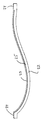
- Fig. 1 shows a windmill blade made according to a usual method.
- a beam 1 is made by winding around a mandrel which later is taken out of the beam.
- Around the beam is glued two half-shells 2 and 3.
- Each half-shell consists of an outer laminate 4, a sandwich core 5, which e.g. can be made in balsa wood or PVC foam, and an inner laminate 6.
- the half-shells are fastened by glue joints at the leading edge 7, at the trailing edge 8, and against the beam 9.
- a blade made according to this usual method initially has three main parts, namely the beam 1 and the two half-shells 2 and 3. According to the circumstances, these main parts may be supplemented with further main parts, e.g. at the root of the blade, for forming transition to pitch bearing and/or rotor hub.
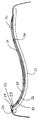
- Fig. 2 shows a windmill blade made according to another usual method.
- Two beams 10 and 11 are made by moulding in separate moulds.
- the two beams are joined with two half-shells 12 and 13.
- the half-shells are fastened by glue joints at the leading edge 14, at the trailing edge 15, and against the beams 16 and 17.
- a blade made according to this prior art method has four main parts, namely the beams 10 and 11 and the two half-shells 12 and 13.
- these main parts may be supplemented with further main parts, e.g. at the root of the blade, for forming transition to pitch bearing and/or rotor hub.
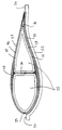
- Fig. 3 shows a windmill blade made by the method according to the invention.
- the blade is an integrated unit, which is constituted by an outer shell 18, a sandwich core 19, an inner shell 20 and a shear web 21.
- the blade may be made with plural shear webs or completely without webs.
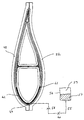
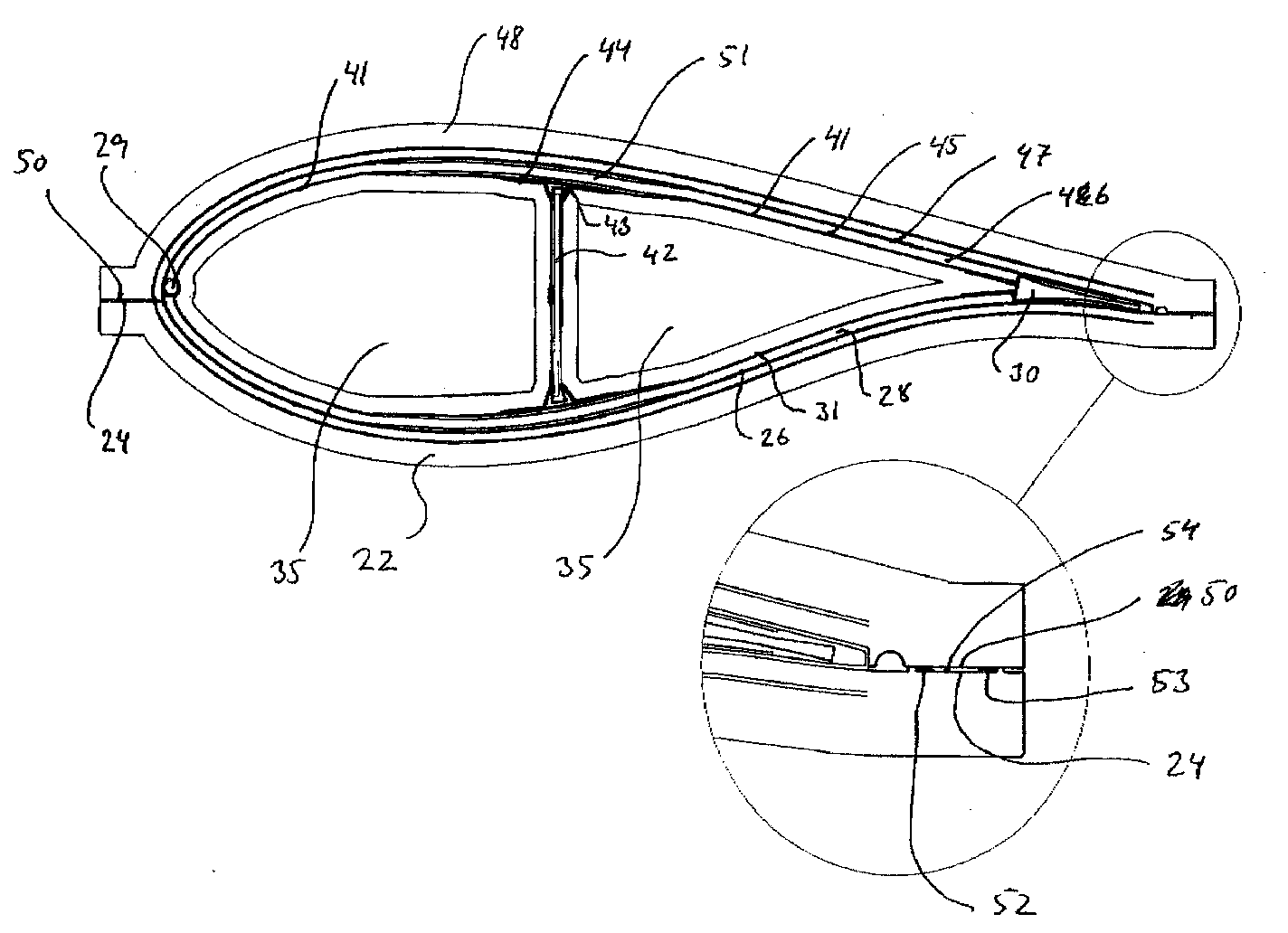
- Fig. 4 shows a cross-section of a mould part suited for making windmill blades with the method according to the invention, where the laminate is made by vacuum injection of thermosetting plastic.
- the mould part 22 is made as a negative impression of a part of the external surface of the blade; as an example here is shown the section termed the pressure side, which during operation of the windmill largely faces the wind.
- the mould part 22 may be treated with a suited release agent on the surface 23 on which the blade in moulded.
- the mould part is provided with closure edges 24 with which tightness through abutment against other mould parts may be achieved.
- the mould part may be achieved with an integrated temperature regulating system 25 with which the temperature of the blade laminate may be changed during setting.
- the mould part 22 may be composed of several parts with joints that are to achieve tightness.
- Fig. 5 shows a first step in making windmill blades by the method according to the invention.
- An outer layer of fibre material 26 is laid in the mould part 22, e.g. mats or web of glass fibre or carbon fibre. Some of the outer layer of fibre material may e.g. extend out beyond the closure edge 24 at the leading edge 27.
- a core material 28 that e.g. may be made in balsawood or PVC foam.
- At one or more suited places, here indicated by the leading edge 27, is provided one or more flow pipes 29, or other kinds of apertures are made along the blade.
- other core parts 30 may be provided, entirely or partly enclosed by the fibre material 26.
- At least a part of the surface of the fibre material 26, the core material 28, the possible flow pipe 29 and possible other core parts 30, are then covered by an inner layer of fibre material 31.
- This inner layer of fibre material 31 may in the same way as the outer layer of fibre material 26 entirely or partly extend beyond the closure edge 24.
- the flow pipe 29 may be provided with holes or saw grooves 32, or in other ways there may be provided flow ducts for resin from the interior of the flow pipe 29 to the core material 28, to the outer layer of fibre material 26 and to the inner layer of fibre material 31.
- the core material 28 and possible other core parts 30 may be provided with tracing 33, or flow paths for resin between the core material 28 and at least one of the two layers 26 and 31 may be provided.
- the core material 28 and possible other core parts 30 may be provided with borings or through-going cuttings 34, or flow ducts for resin between the two surfaces of core material 28 may be provided in other ways.
- Fig. 6 shows a subsequent step in the making of windmill blades with the method according to the invention.
- the mould core 35 and possible shear webs 36 are placed on the inner layer of fibre material 31, the mould core 35 and possible shear webs 36 are placed.
- a mould core in two parts 37 and 38 is utilized that each may be divided into subparts.
- a core part 37 may e.g. consist of a firm inner part 39 that e.g. may be made of wood or composite material.
- the firm inner part 39 may be surrounded on at least a part of its outer side of a flexible outer part 40, which e.g. may be made in foam rubber.
- Each core part 37 is surrounded by a flexible, airtight membrane 41 that e.g. may be made of nylon or silicone rubber.
- the flexible membrane 41 may be treated with a suitable release agent.
- a shear web 36 may be made with an inner core part 42, which e.g. may be made of plywood, balsawood or PVC foam, and which at each side may have a core support part 43 in one or more parts, which e.g. may be made of plywood, balsawood or PVC foam.
- a fibre material 44 e.g. glass or carbon can be placed on each or both sides of the core parts 42 and 43.
- the fibre material 44 may advantageously extend to some extent across the inner layer of fibre material 31, as well as it may extend across the core part 37.
- Fig. 7 shows a subsequent step in making windmill blades with the method according to the invention.
- an inner layer of fibre material 45 is laid that e.g. may be mats or web of glass or carbon fibre, which advantageously may be composed in the same way as the inner layer of fibre material 31 in the lower mould part 22.
- a core material 46 that e.g. may be made in balsawood or PVC foam, and which advantageously may be shaped in the same way as the core material 28 in the lower mould part 22.
- an outer layer of fibre material 47 may e.g. be mats or web of glass or carbon fibre, and may advantageously be composed in the same way as the outer layer of fibre material 26 in the lower mould part 22.
- the parts of the outer layer of fibre material 26 and the inner layer of fibre material 31, which extend beyond the closure edge 24 after laying of the material in the mould part 22, are put together into the inner fibre material 45 and/or the outer fibre material 47, so that overlap of fibre material across the joint face 48 occurring at the closure edge 24 is achieved.
- These layers of fibre materials 26 and 31 that extend beyond the closure edge 24 after laying of the material in the mould part 22 may entirely or partly extend right to the trailing edge when they are laid upon the mould core 35, the fibre material 44 from the possible shear web or webs, and/or the core material 46.
- Fig. 8 shows the next step in making windmill blades by the method according to the invention.
- the mould part 48 may be treated on the surface 49 on which the blade is moulded with a suited release agent.
- the mould part is provided with closure edges 50 with which tightness may be achieved against the first mould part 22.
- the mould part may be provided with an integrated temperature regulation system 25 with which the temperature of the laminate of the blade may be changed during setting.
- the mould part 48 may be composed of several parts with joints that are to attain tightness.
- Fig. 9 shows the next step in making windmill blades by the method according to the invention.
- the mould parts 22 and 48 and on the other hand the flexible membrane 41 around the mould core 35 there is a cavity 51.
- the cavity 51 is partly filled by the fibre materials 26, 31, 44, 45 and 47, the core materials 28, 42, 43, and 46, the flow pipe 29 and possible other core parts 30, as the cavities between the fibre and between the fibre and other parts are filled with air.
- vacuum is applied to the cavity 51 so that at least a substantial part of the air staying between the parts in the cavity is evacuated.
- fibre and core materials etc. are compressed in the cavity 51 as the flexible membrane 41 expands.
- the surfaces between the closure edges 24 and 50 may advantageously be made with at least two sealing arrangements, an internal arrangement 52 and an external arrangement 53, so that between these arrangements there is provided a cavity 54 that may be subjected to vacuum separately from vacuum in the cavity 51, and which may advantageously be maintained at a lower absolute pressure than the cavity 51, whereby possible leakages from the surrounding air to the cavity 51 is prevented.
- Fig. 10 shows the next step in making windmill blades by the method according to the invention.
- the closed mould consisting of the mould parts 22 and 48 with the entire amount of fibre and core materials, mould cores etc., is now turned about its longitudinal axis, so that the flow pipe 29 assumes a position close to the lowest point in a cross-section of the closed mould.
- a connection 55 is established between the flow pipe 29 and a reservoir 56 with suitable resin 57 with the right mix ratio, e.g. polyester, vinyl ester or epoxy.
- the connection 55 that may be a pipe or a tube or combinations thereof, may be provided with a variable flow control valve 58, or in other ways there may be established means for controlling the flow rate in connection 55 to the flow pipe 29, e.g.
- connection 55 may be provided with a stop cock 60, or in other ways there may be established possibility of blocking the flow from the reservoir 56 through the connection 55, e.g. by the flow control valve 58 being able to shut the connection off completely.
- the flow control valve 58 When the blade has the desired position, there is opened up for the flow in the connection 55, and injection is commenced as the resin flows into the cavity 51 under action of the pressure difference between the vacuum established in the cavity and the pressure on the resin 57.
- the flow is regulated with the flow control valve 58, or in other ways, so that a controlled development of the fluid front 61 of the injected resin 62 is maintained with balance between regulated inflow and gravitation.
- the fluid front may e.g. be tried kept approximately horizontal so that the risk of blocking and confinement of larger or lesser amounts of residual air is minimized.
- Fig. 11 shows the next step in making windmill blades according to the invention.
- the flow front 61 has now reached the trailing edge of the blade, and resin now penetrates up into one or more overflow containers 63.
- the injection is terminated by the stop cock 60, or in other ways.
- the temperature regulating system 25 may be active during the whole or a part of the injection process, and particularly after finished injection it may be used to bring the injected laminated up to a temperature that enhances the setting process for the resin.
- the temperature regulating system may also be used for cooling mould and laminate, if the exothermic heat of the setting process is in danger of raising the temperature of mould and laminate to an undesired level.
- one may also completely omit a temperature regulating system in the mould and perform possible final setting in a separate process afterwards.
- the mould core 35 is removed.
- a mould core in two core parts 37 and 38.
- the front core part 37 may be removed in one piece in this example, whereas the rear core part 38 may advantageously be divided into subparts that are removed in the sequence which is most convenient with regard to geometry and handling.
- a core part 37 consists of a firm internal part 39 surrounded by a flexible external part 40, which e.g. may be made of foam rubber and enclosed by a flexible, airtight membrane, over at least apart of its outer side, it may advantageous to apply vacuum on the flexible external part 40, whereby the airtight membrane 41 contracts and is released in relation to the cavity in the moulded blade.
- the flexible, airtight membrane 41 is constituted by plural layers so that possible adherence between the moulded blade and the airtight membrane is limited to the outermost layer of the membrane. It may also be an advantage to provide an airtight layer between the firm internal part 39 and the flexible external part 40 so that vacuum is limited to the flexible external part 40, and larger or lesser pressure loads are not applied on the firm internal part 39.
- a flow pipe 29 which is integrated in the leading edge of the blade.
- the flow pipe may very well be disposed outside the blade itself, e.g. in a recess in the mould, and this recess may constitute the flow duct so that a separate pipe is not necessary.
- Versions with more flow pipes and flow ducts integrated in the blade as well as disposed externally as continuous recesses or tubes in the mould parts may also be envisaged, or partly or entirely in the shape of flow pipes with discrete inlets at the inner sides of the mould parts.
- the fibre material is laid in dry conditions, and where the resin is supplied by vacuum injection.
- a so-called prepeg is laid, where the fibre materials are impregnated with resin in advance, which, after being applied vacuum, is brought to set by the action of heat, UV irradiation, or similar, or fibre materials that are combinations of temperature resisting fibre materials and thermoplastic may be laid, and where the fibre material after laying may be brought to a temperature where the thermoplastic material melts and thereby acts as resin in the finished laminate.
Abstract
Description
- The present invention concerns a method for making windmill blades of composite materials such as glass or carbon fibre reinforced epoxy, polyester, vinyl ester, or thermoplastic.
- Different methods for making windmill blades are known.
- Thus it is known that windmill blades may be made by winding roving tapes or roving bundles around a core or mandrel. Methods for this are inter alia described in US patents 4,242,160 and 4,381,960.
- Such methods by winding have the disadvantage that after setting, the winded item will normally appear with the raw composite material surface as an external surface which is incompatible with many applications, e.g. for windmill blades. A satisfactory surface quality therefore presupposes a finishing treatment, e.g. by the bonding of shells made separately.
- Another drawback by this method is that the winding normally presupposes use of a mandrel with a certain strength which therefore is desired to be reused. In these cases, the method may only be used with items having a geometry allowing removal of the mandrel, which means that the dimensions of the internal cross-section of the cavity at a given distance from the end from which the mandrel it drawn out are not to exceed the dimensions of any of the cross-sections situated between the position in question and the end, and that some tapering in the mould will normally be required in practice. Such a method may thus not be used for e.g. tanks or whole windmill blades.
- It is also prior art that windmill blades may be made by a method where a blade is usually made with two half-shells which are joined at leading and trailing edges by bonding. The half-shells are usually supported inside the blade cavity by one or more beams, which are also joined to the half-shells by bonding, where the beams e.g. may be made in U- or I-shape so that the flanges of these beams form contact surfaces with the half-shells, or where the beams e.g. may be made by winding so that a part of the external surface of the winded beam forms contact surfaces towards the half-shells. The half-shells may e.g. be made of dry fibre materials which are supplied resin by manual laying, vacuum injection or the like, or they may be made of prepeg, where the fibre materials are impregnated in advance with resin which is brought to set by the action of heat, UV-irradiation, or similar. In other embodiments, beams and/or half-shells are made of thermoplastic, e.g. by using fibre materials that are combinations of temperature resisting fibre materials and thermoplastic, and where the fibre material after laying is brought to a temperature where the thermoplastic material melts, thereby acting as resin in the finished laminate.
- However, it is a problem with this method that it may be difficult to ensure a satisfying quality of the glue joints established in the interior of the structure for the mutual joining of the half-shells and for joining possible beams with the half-shells. This is partly due to fundamental problems regarding material technology, partly to more specific manufacturing problems.
- The fundamental problems regarding material technology may summarizingly be described as consequences of the impossibility of having the same material properties in the glue as in the rest of the blade. The reason for this is that the general material properties in the blade shells and the laminates of the possible beams are determined by the fibre reinforcement, which normally has rigidity several orders of magnitude higher than that of the resin, whereby the properties of the resin has minimal significance for the rigidity of the finished laminate. Conversely, the glue is normally made as pure resins (which may consist of other plastics than those used in the laminates) or as mixtures of resins and fillers but without fibre reinforcement. The result is that the elastic modulus of the glue typically deviates an order of magnitude, often several orders of magnitude, from the parts joined with the glue. To this comes that glue materials are often brittle and may therefore be vulnerable to local moments tending to open the glue joint, so-called peeling. Such local moments will particularly occur by very large loads on the blade, where non-linear effects may imply the blade cross-section changing its shape. By virtue of glue materials normally having relatively brittle properties, there may be the subsequent danger that cracks in glue joints propagate far beyond the area in which the original overloads have occurred.
- Among the manufacturing problems, one of the essential is that the glue joints are provided at leading and trailing edge and between beam and shell, so that a glue joint is established on the unprepared surface at the inner side of the shell laminate. The problem of this joint is that the glue surface may only be defined within a certain large range of tolerance. To this comes that in the case of the trailing and leading edge bond the shell laminate has to be reduced towards the edge of the shell when, as e.g. in the case of windmill blades, the case is half-shells where the edges are abutting mutually inclining in order that the glue joint can have nearly uniform thickness. This reduction may not always be provided with the necessary tolerances why a real adaptation will require working of the assembly faces, which in turn will imply a large rise in the costs. Another problem is that the deformations arising in the blade shells in connection with small variations in the manufacturing process can give a varying gap inside the cavity of the item so that it may be difficult to ensure a complete filling of glue of the interspace between beam and shell. All these problems with tolerances have the result that glue joints generally may have varying cross-sections and fillings which in turn implies a risk of considerable stress concentrations in the glue and the adjoining blade shells and beams. Furthermore, it is a problem that most glue materials presupposes that the surfaces to be bonded are ground in advance with the associated problems of maintaining the necessary tolerances. Finally, the glue joints are usually difficult to inspect visually as well as they are difficult to inspect by NDT methods (non-destructive testing) due to the tapering laminate and the irregular geometry of the item.
- It is also a problem with methods based on bonding individual parts of blades that even though individual sections of the blades may be produced in closed processes with small or no environmental loads, this is usually not the case with the bonding itself. Here, workers will usually be exposed to grind dust from dry grinding, partly because it is unfavourable to the subsequent gluing process to perform wet grinding and partly because they are exposed to contact with and/or vapours from the glue material itself, implying need for personal protective means.
- The purpose of the invention is to provide a method for making windmill blades of composite materials so that these may be manufactured in a closed process and mainly in one piece without any glue joints.
- This is achieved with a method of the kind indicated in the introduction, which is peculiar in that the blade is made in one piece in a closed mould and, depending on the type of composite material, possibly also all of or parts of the matrix material, are placed around at least one mould core consisting of an external part of flexible material, that an outer mould part is closed around mould core and possible matrix material, that fibre reinforcement and matrix material are brought into the union relevant for the selected composite material, and that at least a part of the internal part of the mould core is then taken out of the finished windmill blade.
- Several advantages are attained by this method compared with prior art methods.
- By making the blade in one piece, where a substantial part of the outer side is an impression of one or more outer mould parts there is achieved the advantage that by using gelcoat in the mould or by a subsequent simple surface, the blade surface may appear in the quality required with regard to aerodynamic efficiency and aesthetic impression.
- By making the blade in one piece without any glue joints, the prior art problems with glue joints, including problems with tolerances of glue joint dimensions and the difficulties with subsequent inspection of the quality of the glue joints, are eliminated.
- By making the blade in one piece in a closed process, the workers' exposure to possible environmentally hazardous substances in the composite material is eliminated, so that the need for personal protective means may be reduced to an absolute minimum.
- By making the blade in a sandwich construction with a core material which largely runs continuously around the cross-sectional profile of the blade, there is achieved a particularly advantageous combination of production technique and properties of the finished product. The core material may thus be used as evacuation and flow duct by a vacuum based process, and the continuous process ensures uniform cross-sectional properties without disadvantageous transitions between sandwich and solid structure in highly loaded areas. The continuous core material and the real separation of the load bearing part of the laminate in an outer and an inner section furthermore provides the constructional advantage that a possible crack formation in one (outer or inner) laminate only implies a very small risk of propagation to the other laminate. Hereby is achieved a hitherto unknown redundancy of the structure.
- In the following, the method will be explained in detail as reference is made to the Figures. Figures 1 - 2 provides examples of prior art, and Figure 3 indicates a blade made in accordance with the invention. With the Figures 4 - 11, the method is explained in an embodiment where the laminate is made of thermosetting plastic by vacuum injection.
- Fig. 1 shows a windmill blade made according to a usual method. A beam 1 is made by winding around a mandrel which later is taken out of the beam. Around the beam is glued two half-
shells outer laminate 4, asandwich core 5, which e.g. can be made in balsa wood or PVC foam, and aninner laminate 6. The half-shells are fastened by glue joints at the leadingedge 7, at thetrailing edge 8, and against thebeam 9. A blade made according to this usual method initially has three main parts, namely the beam 1 and the two half-shells - Fig. 2 shows a windmill blade made according to another usual method. Two
beams shells edge 14, at thetrailing edge 15, and against thebeams beams shells - Fig. 3 shows a windmill blade made by the method according to the invention. The blade is an integrated unit, which is constituted by an
outer shell 18, asandwich core 19, aninner shell 20 and ashear web 21. In other sections, the blade may be made with plural shear webs or completely without webs. - Fig. 4 shows a cross-section of a mould part suited for making windmill blades with the method according to the invention, where the laminate is made by vacuum injection of thermosetting plastic. The
mould part 22 is made as a negative impression of a part of the external surface of the blade; as an example here is shown the section termed the pressure side, which during operation of the windmill largely faces the wind. Themould part 22 may be treated with a suited release agent on thesurface 23 on which the blade in moulded. The mould part is provided with closure edges 24 with which tightness through abutment against other mould parts may be achieved. The mould part may be achieved with an integratedtemperature regulating system 25 with which the temperature of the blade laminate may be changed during setting. Themould part 22 may be composed of several parts with joints that are to achieve tightness. - Fig. 5 shows a first step in making windmill blades by the method according to the invention. An outer layer of
fibre material 26 is laid in themould part 22, e.g. mats or web of glass fibre or carbon fibre. Some of the outer layer of fibre material may e.g. extend out beyond theclosure edge 24 at theleading edge 27. Upon at least a part of the outer layer offibre material 26 there is provided acore material 28 that e.g. may be made in balsawood or PVC foam. At one or more suited places, here indicated by the leadingedge 27, is provided one ormore flow pipes 29, or other kinds of apertures are made along the blade. Besides thecore material 28, which is placed upon the outer layer offibre material 26,other core parts 30 may be provided, entirely or partly enclosed by thefibre material 26. At least a part of the surface of thefibre material 26, thecore material 28, thepossible flow pipe 29 and possibleother core parts 30, are then covered by an inner layer offibre material 31. This inner layer offibre material 31 may in the same way as the outer layer offibre material 26 entirely or partly extend beyond theclosure edge 24. Theflow pipe 29 may be provided with holes or sawgrooves 32, or in other ways there may be provided flow ducts for resin from the interior of theflow pipe 29 to thecore material 28, to the outer layer offibre material 26 and to the inner layer offibre material 31. Thecore material 28 and possibleother core parts 30 may be provided with tracing 33, or flow paths for resin between thecore material 28 and at least one of the twolayers core material 28 and possibleother core parts 30 may be provided with borings or through-goingcuttings 34, or flow ducts for resin between the two surfaces ofcore material 28 may be provided in other ways. - Fig. 6 shows a subsequent step in the making of windmill blades with the method according to the invention. On the inner layer of
fibre material 31, themould core 35 and possibleshear webs 36 are placed. In the shown example, a mould core in twoparts core part 37 may e.g. consist of a firminner part 39 that e.g. may be made of wood or composite material. The firminner part 39 may be surrounded on at least a part of its outer side of a flexibleouter part 40, which e.g. may be made in foam rubber. Eachcore part 37 is surrounded by a flexible,airtight membrane 41 that e.g. may be made of nylon or silicone rubber. Theflexible membrane 41 may be treated with a suitable release agent. Ashear web 36 may be made with aninner core part 42, which e.g. may be made of plywood, balsawood or PVC foam, and which at each side may have acore support part 43 in one or more parts, which e.g. may be made of plywood, balsawood or PVC foam. On each or both sides of thecore parts fibre material 44 of e.g. glass or carbon can be placed. Thefibre material 44 may advantageously extend to some extent across the inner layer offibre material 31, as well as it may extend across thecore part 37. - Fig. 7 shows a subsequent step in making windmill blades with the method according to the invention. Across the
core part 35 and thefibre material 44 from the possible shear web orwebs 36, an inner layer offibre material 45 is laid that e.g. may be mats or web of glass or carbon fibre, which advantageously may be composed in the same way as the inner layer offibre material 31 in thelower mould part 22. On top of at least a part of the inner layer offibre material 45 there is provided acore material 46, that e.g. may be made in balsawood or PVC foam, and which advantageously may be shaped in the same way as thecore material 28 in thelower mould part 22. In some cases, it will be advantageous to postpone the laying of theflow pipe 29 as described above instep 5 to this stage of the process. At least a part of the surface of thefibre material 45, thecore material 46, thepossible flow pipe 29 and possibleother core parts 30 are then covered by an outer layer offibre material 47. This outer layer offibre material 47 may e.g. be mats or web of glass or carbon fibre, and may advantageously be composed in the same way as the outer layer offibre material 26 in thelower mould part 22. In the process of laying theinner fibre material 45,core material 46 andouter fibre material 47, the parts of the outer layer offibre material 26 and the inner layer offibre material 31, which extend beyond theclosure edge 24 after laying of the material in themould part 22, are put together into theinner fibre material 45 and/or theouter fibre material 47, so that overlap of fibre material across thejoint face 48 occurring at theclosure edge 24 is achieved. These layers offibre materials closure edge 24 after laying of the material in themould part 22 may entirely or partly extend right to the trailing edge when they are laid upon themould core 35, thefibre material 44 from the possible shear web or webs, and/or thecore material 46. - Fig. 8 shows the next step in making windmill blades by the method according to the invention. Across the outer layer of
fibre material 47 there is disposed one ormore mould parts 48 that are shaped as a negative impression of a part of the outer surface of the blade, here illustrated the part termed the suction side, and which during operation of the windmill largely faces away from the wind. Themould part 48 may be treated on thesurface 49 on which the blade is moulded with a suited release agent. The mould part is provided with closure edges 50 with which tightness may be achieved against thefirst mould part 22. The mould part may be provided with an integratedtemperature regulation system 25 with which the temperature of the laminate of the blade may be changed during setting. Themould part 48 may be composed of several parts with joints that are to attain tightness. - Fig. 9 shows the next step in making windmill blades by the method according to the invention. Between on the one hand the
mould parts flexible membrane 41 around themould core 35 there is acavity 51. Thecavity 51 is partly filled by thefibre materials core materials flow pipe 29 and possibleother core parts 30, as the cavities between the fibre and between the fibre and other parts are filled with air. Now, vacuum is applied to thecavity 51 so that at least a substantial part of the air staying between the parts in the cavity is evacuated. Thereby, fibre and core materials etc. are compressed in thecavity 51 as theflexible membrane 41 expands. In order to ensure good sealing, the surfaces between the closure edges 24 and 50 may advantageously be made with at least two sealing arrangements, aninternal arrangement 52 and anexternal arrangement 53, so that between these arrangements there is provided acavity 54 that may be subjected to vacuum separately from vacuum in thecavity 51, and which may advantageously be maintained at a lower absolute pressure than thecavity 51, whereby possible leakages from the surrounding air to thecavity 51 is prevented. - Fig. 10 shows the next step in making windmill blades by the method according to the invention. The closed mould, consisting of the
mould parts flow pipe 29 assumes a position close to the lowest point in a cross-section of the closed mould. Aconnection 55 is established between theflow pipe 29 and areservoir 56 withsuitable resin 57 with the right mix ratio, e.g. polyester, vinyl ester or epoxy. Theconnection 55 that may be a pipe or a tube or combinations thereof, may be provided with a variableflow control valve 58, or in other ways there may be established means for controlling the flow rate inconnection 55 to theflow pipe 29, e.g. in the form of pressure control of thespace 59 over theresin 57. Theconnection 55 may be provided with astop cock 60, or in other ways there may be established possibility of blocking the flow from thereservoir 56 through theconnection 55, e.g. by theflow control valve 58 being able to shut the connection off completely. When the blade has the desired position, there is opened up for the flow in theconnection 55, and injection is commenced as the resin flows into thecavity 51 under action of the pressure difference between the vacuum established in the cavity and the pressure on theresin 57. During the injection, the flow is regulated with theflow control valve 58, or in other ways, so that a controlled development of thefluid front 61 of the injectedresin 62 is maintained with balance between regulated inflow and gravitation. The fluid front may e.g. be tried kept approximately horizontal so that the risk of blocking and confinement of larger or lesser amounts of residual air is minimized. - Fig. 11 shows the next step in making windmill blades according to the invention. The
flow front 61 has now reached the trailing edge of the blade, and resin now penetrates up into one or more overflow containers 63. When there is pure resin in the relevant overflow containers, the injection is terminated by thestop cock 60, or in other ways. Thetemperature regulating system 25 may be active during the whole or a part of the injection process, and particularly after finished injection it may be used to bring the injected laminated up to a temperature that enhances the setting process for the resin. Depending on the embodiment, the temperature regulating system may also be used for cooling mould and laminate, if the exothermic heat of the setting process is in danger of raising the temperature of mould and laminate to an undesired level. However, one may also completely omit a temperature regulating system in the mould and perform possible final setting in a separate process afterwards. - After finished setting, the moulds are opened and the finished blade is taken out.
- Before or after the blade is taken out, the
mould core 35 is removed. In the shown example there is used a mould core in twocore parts front core part 37 may be removed in one piece in this example, whereas therear core part 38 may advantageously be divided into subparts that are removed in the sequence which is most convenient with regard to geometry and handling. If acore part 37 consists of a firminternal part 39 surrounded by a flexibleexternal part 40, which e.g. may be made of foam rubber and enclosed by a flexible, airtight membrane, over at least apart of its outer side, it may advantageous to apply vacuum on the flexibleexternal part 40, whereby theairtight membrane 41 contracts and is released in relation to the cavity in the moulded blade. For this process, it may be an advantage that the flexible,airtight membrane 41 is constituted by plural layers so that possible adherence between the moulded blade and the airtight membrane is limited to the outermost layer of the membrane. It may also be an advantage to provide an airtight layer between the firminternal part 39 and the flexibleexternal part 40 so that vacuum is limited to the flexibleexternal part 40, and larger or lesser pressure loads are not applied on the firminternal part 39. - In the above, the process is described with the use of a
flow pipe 29 which is integrated in the leading edge of the blade. The flow pipe may very well be disposed outside the blade itself, e.g. in a recess in the mould, and this recess may constitute the flow duct so that a separate pipe is not necessary. Versions with more flow pipes and flow ducts integrated in the blade as well as disposed externally as continuous recesses or tubes in the mould parts may also be envisaged, or partly or entirely in the shape of flow pipes with discrete inlets at the inner sides of the mould parts. - In the above is described a practical embodiment of the method, where the fibre material is laid in dry conditions, and where the resin is supplied by vacuum injection. In other practical embodiments, a so-called prepeg is laid, where the fibre materials are impregnated with resin in advance, which, after being applied vacuum, is brought to set by the action of heat, UV irradiation, or similar, or fibre materials that are combinations of temperature resisting fibre materials and thermoplastic may be laid, and where the fibre material after laying may be brought to a temperature where the thermoplastic material melts and thereby acts as resin in the finished laminate.
- Combinations of the practical embodiment of the method with fibre material laid in dry condition and where a part of laid material is in form of finished fibre reinforced parts, e.g. previously moulded part for the blade root or longitudinally pultruded profiles. Combinations of materials in the laying may also be envisaged, which otherwise in prior art methods are held separate to each other. E.g. mats in prepeg may also be envisaged where the integrated resin contributes to the injection of the surrounding dry fibre material to a certain degree, and where the amount of resin needed for complete impregnation of the laminate is provided by vacuum injection as described above.
Claims (10)
- A method for making a windmill blade of composite materials which include a fibre reinforced matrix material, the improvement comprising that the blade is made in one piece in a closed mould and comprising steps that provide:a mould core with a flexible external core part and an internal, firm or workable core part, and outer mould parts arranged to close around the mould core for formation of a mould cavity there between,that composite material and possible core inserts are laid on an outer mould part and/or the mould core,that the outer mould parts are closed around the mould core and around the composite material placed in the mould cavity,that the composite material is set,that the outer mould parts are removed, andthat the mould core is taken out of the shape permanent blade before or after removing the outer mould parts.
- A method according to claim 1, wherein some of the required matrix material is used in connection with the reinforcing fibre when laying the composite material and where additional matrix material is added after closing the mould.
- A method according to claim 1 or 2, wherein the composite material is laid around a core material for forming the blade as a sandwich structure, where the core material is used for evacuation and flow at vacuum formation of the blade as the mould cavity is subjected to vacuum whereby air is evacuated simultaneously with composite materials and possible core inserts being pressed against the inner side of the outer mould parts due to the flexible external core part of the mould core, and where the matrix material is injected formation of the mould cavity by vacuum.
- A method according to claim 3, wherein the material is injected through a duct disposed at a vertical underside of the mould cavity and with a flow regulated for controlling an upwardly advancing fluid front of the matrix material so as to avoid confinement of air in the mould cavity.
- A method according to claim 3 or 4, wherein an outer layer of fibre material extending beyond a side edge of the mould cavity is laid on a first outer mould part, where at least one flow pipe is placed at the said side edge for injecting matrix material, where a layer of core material and possible other core parts are placed, where an inner layer of fibre material extending beyond the said side edge is laid, where the mould core is placed in the layers that are laid, where the fibre material extending beyond the side edge is folded in over the mould core and the flow pipe, where a layer of core material and an outer layer of fibre material are laid on the mould core, where a second outer mould part is placed in close contact with the first outer mould part, where vacuum is applied to the mould cavity and where the matrix material is injected via the flow pipe.
- A method according to any preceding claim, wherein core inserts are disposed between the layers of fibre material and are taken out of the mould together with the composite material for making a blade in which such inserts constitute structural elements in the finished blade.
- A method according to any preceding claim, wherein thermal setting is used, and wherein the temperature in the composite materials of the blade are changed during the setting by using a temperature control system in at least one of the mould parts.
- A method according to any of claims 3 - 7, wherein the core material is provided with through-going passages used as ducts for fluid matrix material between the two layers of fibre material.
- A method according to any preceding claim, wherein injection of the matrix material is terminated when fluid matrix material is pressed out of apertures at the upwardly facing side edge of the blade.
- A method according to any preceding claim, wherein the mould core is provided as a plurality of separate sections.
Priority Applications (1)
| Application Number | Priority Date | Filing Date | Title |
|---|---|---|---|
| DK02024766T DK1310351T3 (en) | 2001-11-13 | 2002-11-07 | Process for manufacturing wind turbine blades |
Applications Claiming Priority (4)
| Application Number | Priority Date | Filing Date | Title |
|---|---|---|---|
| DK200101686 | 2001-11-13 | ||
| DKPA200101686 | 2001-11-13 | ||
| DK200101745 | 2001-11-22 | ||
| DK200101745A DK176335B1 (en) | 2001-11-13 | 2001-11-22 | Process for manufacturing wind turbine blades |
Publications (2)
| Publication Number | Publication Date |
|---|---|
| EP1310351A1 true EP1310351A1 (en) | 2003-05-14 |
| EP1310351B1 EP1310351B1 (en) | 2006-04-19 |
Family
ID=26069092
Family Applications (1)
| Application Number | Title | Priority Date | Filing Date |
|---|---|---|---|
| EP02024766A Expired - Lifetime EP1310351B1 (en) | 2001-11-13 | 2002-11-07 | Method for manufacturing windmill blades |
Country Status (6)
| Country | Link |
|---|---|
| US (1) | US7473385B2 (en) |
| EP (1) | EP1310351B1 (en) |
| AT (1) | ATE323593T1 (en) |
| DE (1) | DE60210729T2 (en) |
| DK (2) | DK176335B1 (en) |
| ES (1) | ES2262747T3 (en) |
Cited By (88)
| Publication number | Priority date | Publication date | Assignee | Title |
|---|---|---|---|---|
| FR2874852A1 (en) * | 2004-09-03 | 2006-03-10 | Digital Composite Systems Sarl | METHOD FOR MANUFACTURING A HOLLOW EXTENDED HOLLOW PIECE OF COMPOSITE MATERIAL SUCH AS A WINDMILL BLADE INCLUDING A BRAIDED HULL, WINDBREAK BLADE, AND TRIMMER MACHINE |
| EP1764307A1 (en) * | 2005-09-14 | 2007-03-21 | EADS Construcciones Aeronauticas, S.A. | Process for manufacturing a monolithic leading edge |
| EP1772621A2 (en) * | 2005-10-06 | 2007-04-11 | NORDEX ENERGY GmbH | Manufacturing method of a hole in a fibre reinforced composite and rotor blade for wind turbine with such a hole |
| EP1779997A2 (en) * | 2005-10-28 | 2007-05-02 | General Electric Company | Methods of making wind turbine rotor blades |
| WO2007128314A1 (en) * | 2006-05-09 | 2007-11-15 | Vestas Wind Systems A/S | Lightning protection system for a wind turbine rotor blade and a method for manufacturing such a blade |
| EP1880833A1 (en) * | 2006-07-19 | 2008-01-23 | National University of Ireland, Galway | Composite articles comprising in-situ-polymerisable thermoplastic material and processes for their construction |
| WO2008086805A2 (en) * | 2007-01-16 | 2008-07-24 | Danmarks Tekniske Universitet | Reinforced blade for wind turbine |
| WO2009062507A2 (en) * | 2007-11-14 | 2009-05-22 | Vestas Wind Systems A/S | Wind turbine blade and method for manufacturing a wind turbine blade |
| WO2009083531A1 (en) * | 2007-12-28 | 2009-07-09 | Vestas Wind Systems A/S | A tubular element, the related method and tools to produce it |
| WO2009112321A1 (en) * | 2008-03-12 | 2009-09-17 | Airbus Operations Gmbh | Method for producing an integral fiber composite part |
| WO2009139619A1 (en) * | 2008-05-16 | 2009-11-19 | Darwind Holding B.V. | A method of manufacturing a turbine blade half, a turbine blade half, a method of manufacturing a turbine blade, and a turbine blade |
| EP2123431A1 (en) * | 2008-05-21 | 2009-11-25 | Siemens Aktiengesellschaft | Method for manufacturing a composite and a wind turbine blade |
| EP2153964A1 (en) | 2008-08-14 | 2010-02-17 | Lm Glasfiber A/S | A method of manufacturing a wind turbine blade comprising steel wire reinforced matrix material |
| WO2010018229A1 (en) * | 2008-08-14 | 2010-02-18 | Lm Glasfiber A/S | A method of manufacturing a wind turbine blade shell part comprising a magnetisable material |
| NL1035861C (en) * | 2008-08-25 | 2010-03-11 | Darwind Holding B V | A method of manufacturing a turbine blade half, a turbine blade half, a method of manufacturing a turbine blade, and a turbine blade. |
| US7722348B1 (en) * | 2007-12-31 | 2010-05-25 | Quenneville Marc A | Vacuum assisted molding |
| LU91530B1 (en) * | 2009-02-20 | 2010-08-23 | Constant Seiwerath | Rotor blade production |
| EP2226186A1 (en) | 2009-03-06 | 2010-09-08 | Lm Glasfiber A/S | Method and manufacturing line for manufacturing wind turbine blades |
| WO2010100251A1 (en) | 2009-03-06 | 2010-09-10 | Lm Glasfiber A/S | Method and manufacturing line for manufacturing wind turbine blades |
| EP2255957A1 (en) | 2009-05-25 | 2010-12-01 | Lm Glasfiber A/S | A method of manufacturing a composite structure with a prefabricated reinforcement element |
| CN101905538A (en) * | 2010-01-14 | 2010-12-08 | 连云港中复连众复合材料集团有限公司 | Process for integrally manufacturing megawatt wind turbine blade |
| WO2011000381A3 (en) * | 2009-06-30 | 2011-05-26 | Vestas Wind Systems A/S | Method of manufacturing a wind turbine blade comprising two members being joined by adhesion |
| EP2335909A1 (en) | 2009-12-18 | 2011-06-22 | Siemens Aktiengesellschaft | Mould and method to built up a blade |
| US20110162787A1 (en) * | 2009-03-31 | 2011-07-07 | Bakhuis Jan W | Retrofit sleeve for wind turbine blade |
| US7980840B2 (en) | 2008-04-03 | 2011-07-19 | Siemens Aktiengesellschaft | Mould and method for vacuum assisted resin transfer moulding |
| US8007624B2 (en) | 2008-05-05 | 2011-08-30 | Siemens Aktiengesellschaft | Method of manufacturing wind turbine blades comprising composite materials |
| WO2011107166A1 (en) | 2010-03-03 | 2011-09-09 | Siemens Aktiengesellschaft | Method and mould for moulding a wind turbine blade |
| EP2377674A1 (en) * | 2010-04-16 | 2011-10-19 | Siemens Aktiengesellschaft | Method for manufacturing a wind turbine rotor blade and wind turbine rotor blade |
| EP2383092A1 (en) * | 2010-03-25 | 2011-11-02 | REpower Systems AG | Device and unit mould for the production of rotor blades for wind energy facilities and method for producing same |
| EP2388131A1 (en) | 2010-05-20 | 2011-11-23 | Siemens Aktiengesellschaft | Method of moulding a wind turbine blade using a release film, and said film |
| US8075277B2 (en) | 2006-05-26 | 2011-12-13 | Siemens Aktiengesellschaft | Method for casting a component and a component comprising at least partly of fibre-reinforced plastic laminate |
| EP2400147A1 (en) | 2010-06-25 | 2011-12-28 | Siemens Aktiengesellschaft | Root of the blade of a wind turbine |
| EP2402594A1 (en) | 2010-07-01 | 2012-01-04 | Lm Glasfiber A/S | Wind turbine blade for a rotor of a wind turbine |
| EP2418072A1 (en) | 2010-08-13 | 2012-02-15 | Lm Glasfiber A/S | A method of manufacturing an elongated composite structure |
| EP2441951A1 (en) | 2010-10-13 | 2012-04-18 | Siemens Aktiengesellschaft | Method for manufacturing a wind turbine rotor blade |
| CN102518567A (en) * | 2011-12-26 | 2012-06-27 | 无锡韦伯风能技术有限公司 | Lightweight high-strength blade and manufacturing technology thereof |
| EP2476540A1 (en) | 2011-01-18 | 2012-07-18 | Siemens Aktiengesellschaft | Stiffening sheet for use in a fibre reinforced laminate, fibre reinforced laminate and wind turbine blade, and a method of manufacturing a fibre reinforced laminate |
| WO2012140058A2 (en) | 2011-04-11 | 2012-10-18 | Lm Wind Power A/S | A wind turbine blade comprising resistive heating means |
| WO2012130339A3 (en) * | 2011-03-25 | 2012-12-13 | Siemens Aktiengesellschaft | Facility and method for manufacturing a rotor blade of a wind turbine and method for setting up the facility |
| EP2543499A1 (en) | 2011-07-06 | 2013-01-09 | LM Wind Power A/S | Wind turbine blade comprising metal filaments and carbon fibres and a method of manufacturing thereof |
| EP2570254A1 (en) | 2011-09-15 | 2013-03-20 | Siemens Aktiengesellschaft | Method for manufacturing a wind turbine rotor blade with a shear web |
| CN102990938A (en) * | 2011-09-15 | 2013-03-27 | 通用电气公司 | Method and system for producing a wind turbine rotor blade |
| WO2013053666A1 (en) | 2011-10-11 | 2013-04-18 | Bayer Intellectual Property Gmbh | Composite profile and method for manufacturing a composite profile |
| WO2013053667A1 (en) | 2011-10-11 | 2013-04-18 | Bayer Intellectual Property Gmbh | Method of manufacturing a composite panel |
| WO2013060493A1 (en) | 2011-10-28 | 2013-05-02 | Siemens Aktiengesellschaft | Wind turbine blade comprising a vortex-generator |
| US8454318B2 (en) | 2006-12-15 | 2013-06-04 | Bladena Aps | Reinforced aerodynamic profile |
| CN103213286A (en) * | 2012-01-20 | 2013-07-24 | 西门子公司 | Wind turbine rotor blade with trailing edge comprising rovings |
| EP2626194A1 (en) | 2012-02-07 | 2013-08-14 | Siemens Aktiengesellschaft | Method of manufacturing a turbine blade, system for manufacturing a turbine blade and intermediate member for manufacturing a turbine blade |
| ES2400100R1 (en) * | 2011-03-14 | 2013-09-27 | Dena Desarrollos S L | PARARRAYOS SYSTEM FOR WIND TURBINE SHOES |
| FR2992890A1 (en) * | 2012-07-04 | 2014-01-10 | Heol Composites | Hollow composite material part manufacturing method, involves sealingly attaching parts of female mold, and compressing membrane against fibrous materials such that hardening of hollow part is ensured |
| US8632312B2 (en) | 2007-01-25 | 2014-01-21 | Bladena Aps | Reinforced blade for wind turbine |
| WO2014070379A1 (en) * | 2012-10-31 | 2014-05-08 | The Boeing Company | Over-molded vacuum barrier and inner mold line bag carrier with soluble details in trapped closed mold tooling |
| WO2014070341A1 (en) * | 2012-10-31 | 2014-05-08 | The Boeing Company | System and method for facilitating fluid movement in closed molds for composite parts |
| EP2466122A3 (en) * | 2010-12-17 | 2014-07-23 | Vestas Wind Systems A/S | Wind turbine blade and method for manufacturing a wind turbine blade with vortex generators |
| US8807953B2 (en) | 2008-06-24 | 2014-08-19 | Bladena Aps | Reinforced wind turbine blade |
| WO2014044445A3 (en) * | 2012-09-19 | 2014-08-28 | Wobben Properties Gmbh | Process for producing wind power plant rotor blades and for producing a mould core therefor |
| WO2014101918A3 (en) * | 2012-12-31 | 2014-08-28 | Vestas Wind Systems A/S | Device for accessing the sides of a wind turbine blade mould |
| US20150075713A1 (en) * | 2013-09-19 | 2015-03-19 | Siemens Aktiengesellschaft | Method for applying fibre material on a vertical surface |
| EP2886322A1 (en) | 2013-12-19 | 2015-06-24 | Bayer MaterialScience AG | Method for producing compound components |
| WO2015114098A1 (en) | 2014-01-31 | 2015-08-06 | Lm Wp Patent Holding A/S | Wind turbine blade part manufactured in two steps |
| US9145203B2 (en) | 2012-10-31 | 2015-09-29 | The Boeing Company | Natural laminar flow wingtip |
| WO2015197739A1 (en) | 2014-06-26 | 2015-12-30 | Covestro Deutschland Ag | Composite components on the basis of hydrophobic polyols |
| GB2529186A (en) * | 2014-08-12 | 2016-02-17 | Vestas Wind Sys As | Improvements relating to wind turbine blade manufacture |
| US9416768B2 (en) | 2009-12-02 | 2016-08-16 | Bladena Aps | Reinforced airfoil shaped body |
| US9498903B2 (en) | 2012-10-31 | 2016-11-22 | The Boeing Company | System and method for manufacturing monolithic structures using expanding internal tools |
| CN106564197A (en) * | 2016-11-02 | 2017-04-19 | 上海复合材料科技有限公司 | Manufacturing method of automobile linkage rod made of composite material |
| CN107791543A (en) * | 2017-10-30 | 2018-03-13 | 国电联合动力技术有限公司 | Trailing edge bonding angle formpiston preparation method and trailing edge bonding angle preparation method |
| WO2018215457A1 (en) | 2017-05-22 | 2018-11-29 | Lm Wind Power International Technology Ii Aps | Wind turbine blade and method of assembly of blade elements to form a wind turbine blade |
| FR3075688A1 (en) * | 2017-12-21 | 2019-06-28 | Heol Composites | METHOD FOR MANUFACTURING A HOLLOW PIECE OF COMPOSITE MATERIALS AND HOLLOW PIECE OBTAINED BY SAID METHOD |
| WO2020069982A1 (en) | 2018-10-02 | 2020-04-09 | Covestro Deutschland Ag | Infusion device and method for producing fiber-reinforced composite parts |
| WO2020122863A1 (en) * | 2018-12-11 | 2020-06-18 | General Electric Company | Method for manufacturing a fiber reinforced polymer composite beam, particularly a spar beam for a wind turbine rotor blade |
| EP3744494A1 (en) | 2019-05-28 | 2020-12-02 | Siemens Gamesa Renewable Energy A/S | A mold for manufacturing a wind turbine blade and a method for manufacturing a wind turbine blade |
| EP3747639A1 (en) | 2019-06-07 | 2020-12-09 | Siemens Gamesa Renewable Energy A/S | Method for manufacturing a wind turbine blade and wind turbine blade |
| EP3838576A1 (en) | 2019-12-19 | 2021-06-23 | Siemens Gamesa Renewable Energy A/S | Method for manufacturing a wind turbine blade |
| US11092132B2 (en) | 2013-07-12 | 2021-08-17 | Lm Wp Patent Holding A/S | Method of manufacturing a wind turbine blade |
| EP3885112A1 (en) | 2020-03-27 | 2021-09-29 | Siemens Gamesa Renewable Energy A/S | Method for manufacturing a wind turbine blade and mold for manufacturing a wind turbine blade |
| EP3907062A1 (en) | 2020-05-07 | 2021-11-10 | Siemens Gamesa Renewable Energy A/S | Method for manufacturing a wind turbine blade and fixture for manufacturing a wind turbine blade |
| EP3944954A1 (en) | 2020-07-27 | 2022-02-02 | Siemens Gamesa Renewable Energy A/S | Manufacturing of a wind turbine rotor blade |
| WO2022073967A1 (en) | 2020-10-07 | 2022-04-14 | Lm Wind Power A/S | A precured fibrous strip for a load-carrying structure and method of manufacturing a spar cap for a win turbine blade |
| WO2022074215A1 (en) | 2020-10-09 | 2022-04-14 | Lm Wind Power A/S | A method of manufacturing a wind turbine blade part with a flow-enhancing mat, flow enhancing mat and spar cap obtained by said method |
| US11313346B2 (en) | 2018-06-08 | 2022-04-26 | Siemens Gamesa Renewable Energy A/S | Method of manufacturing wind turbine rotor blades |
| EP4050202A1 (en) | 2021-02-24 | 2022-08-31 | LM Wind Power A/S | A method of assembling a wind turbine blade |
| WO2022184753A1 (en) | 2021-03-04 | 2022-09-09 | Lm Wind Power A/S | Fibre-reinforcement fabric for a wind turbine blade component |
| WO2023281407A1 (en) * | 2021-07-06 | 2023-01-12 | Bladeworks S.R.L. | A method for manufacturing a wind blade and a wind blade manufactured with said method |
| EP4173808A1 (en) | 2021-11-02 | 2023-05-03 | LM Wind Power A/S | Debagging system and method for use in a debagging process during the manufacture of a wind turbine blade |
| EP4249222A1 (en) | 2022-03-23 | 2023-09-27 | Siemens Gamesa Renewable Energy A/S | Material layup apparatus and method for producing wind turbine blades using fiber plies |
| EP4279255A1 (en) | 2022-05-19 | 2023-11-22 | Siemens Gamesa Renewable Energy A/S | Method for manufacturing a wind turbine blade and mold arrangement |
| TWI838616B (en) | 2020-03-27 | 2024-04-11 | 丹麥商西門子歌美颯再生能源公司 | Method for manufacturing a wind turbine blade |
Families Citing this family (78)
| Publication number | Priority date | Publication date | Assignee | Title |
|---|---|---|---|---|
| WO2005071261A1 (en) * | 2004-01-26 | 2005-08-04 | Vestas Wind Systems A/S | Methods of handling a wind turbine blade and system therefor |
| EP1743480B1 (en) * | 2004-05-04 | 2008-08-20 | Thomson Licensing | Structure for mounting a light engine in a projection display |
| ITPD20040149A1 (en) * | 2004-06-11 | 2004-09-11 | Bottacin Giuseppe | PROCESS FOR THE PRODUCTION OF MONOLITHIC HOLLOW WHEELS IN RESIN REINFORCED WITH HIGH PRESSURE POLYMERIZED FIBERS AND PRODUCT OBTAINED |
| CN100385114C (en) * | 2005-04-01 | 2008-04-30 | 同济大学 | Wind machine's laminae made from composite material and preparation method |
| AU2006270023B2 (en) * | 2005-07-15 | 2011-06-16 | Xzeres Corp. | Wind turbine and method of manufacture |
| JP4699255B2 (en) * | 2006-03-24 | 2011-06-08 | 三菱重工業株式会社 | Windmill wing |
| US7824592B2 (en) * | 2006-09-22 | 2010-11-02 | General Electric Company | Bond line forming method |
| CN101595300A (en) * | 2007-01-29 | 2009-12-02 | 丹麦技术大学 | Wind turbine blade |
| US7895745B2 (en) | 2007-03-09 | 2011-03-01 | General Electric Company | Method for fabricating elongated airfoils for wind turbines |
| GB2447964B (en) | 2007-03-29 | 2012-07-18 | Gurit Uk Ltd | Moulding material |
| DK1990178T3 (en) * | 2007-05-07 | 2010-10-04 | Siemens Ag | Method of manufacturing a rotor blade for a wind turbine |
| DK2110552T4 (en) | 2008-04-15 | 2019-04-08 | Siemens Ag | Wind turbine blade with an integrated lightning arrester and method for manufacturing it |
| GB2459439A (en) * | 2008-04-21 | 2009-10-28 | Rolls Royce Plc | Producing an article containing a protective member by moulding |
| US20090273111A1 (en) * | 2008-04-30 | 2009-11-05 | Bha Group, Inc. | Method of making a wind turbine rotor blade |
| CN102066747A (en) * | 2008-06-23 | 2011-05-18 | 丹麦技术大学 | A wind turbine blade with angled girders |
| US8807954B2 (en) * | 2008-08-25 | 2014-08-19 | Vestas Wind Systems A/S | Assembly and method of preparing an assembly |
| US7857595B2 (en) * | 2008-09-12 | 2010-12-28 | General Electric Company | Molded reinforced shear web cores |
| DE102008046991A1 (en) † | 2008-09-12 | 2010-03-25 | Mt Aerospace Ag | Load-bearing thick-walled fiber composite structural component and method for its production |
| US8092187B2 (en) * | 2008-12-30 | 2012-01-10 | General Electric Company | Flatback insert for turbine blades |
| DE102009002501A1 (en) * | 2009-04-20 | 2010-10-28 | Wobben, Aloys | Rotor blade element and manufacturing process |
| DK2295235T3 (en) * | 2009-08-20 | 2013-07-29 | Siemens Ag | Fiber-reinforced plastic structure and method for making the fiber-reinforced plastic structure |
| US8529818B2 (en) | 2009-09-30 | 2013-09-10 | General Electric Company | Automated fiber placement in female mold |
| DE102009051459B4 (en) * | 2009-10-30 | 2014-04-30 | Audi Ag | Method for producing a hollow composite fiber composite part |
| DE102009046293B4 (en) * | 2009-11-02 | 2013-03-28 | Repower Systems Ag | Rotor blade with drainage hole |
| DE102009058101A1 (en) * | 2009-12-12 | 2011-06-16 | Bayer Materialscience Ag | Use of layer structures in wind turbines |
| EP2354106A1 (en) | 2010-02-05 | 2011-08-10 | 3B | Glass fibre composition and composite material reinforced therewith |
| EP2354104A1 (en) | 2010-02-05 | 2011-08-10 | 3B | Glass fibre composition and composite material reinforced therewith |
| EP2354105A1 (en) | 2010-02-05 | 2011-08-10 | 3B | Glass fibre composition and composite material reinforced therewith |
| DK2357069T3 (en) | 2010-02-15 | 2013-01-02 | Siemens Ag | Mold, apparatus and method for making a composite part containing at least one fiber reinforced matrix |
| US8043066B2 (en) * | 2010-06-08 | 2011-10-25 | General Electric Company | Trailing edge bonding cap for wind turbine rotor blades |
| WO2012003836A1 (en) * | 2010-07-08 | 2012-01-12 | Vestas Wind Systems A/S | Turbine blade temperature measurement system and method of manufacture of turbine blades |
| DE102010033627B4 (en) * | 2010-08-06 | 2012-05-31 | Daimler Ag | Shaped plastic multilayer component with endlessly reinforced fiber layers and method for its production |
| US8894791B1 (en) * | 2010-09-09 | 2014-11-25 | Groen Brothers Aviation, Inc. | Composite rotor blade manufacturing method and apparatus |
| US9144944B1 (en) * | 2010-09-09 | 2015-09-29 | Groen Brothers Aviation, Inc. | Rotor blade spar manufacturing apparatus and method |
| CN102092134B (en) * | 2010-11-08 | 2013-05-15 | 天津东汽风电叶片工程有限公司 | Integrated infusion molding method for front and rear edge flanges and shell of wind turbine blade |
| ES2387432B1 (en) * | 2011-02-25 | 2013-07-29 | Francisco Javier Garcia Castro | PROCEDURE FOR THE MANUFACTURE OF WIND SHOES, BLADES FOR WINGS, WINGS OR SIMILAR STRUCTURES AND STRUCTURE IN THE FORM OF A SHOVEL OBTAINED BY MEANS OF THIS PROCEDURE |
| US8900671B2 (en) * | 2011-02-28 | 2014-12-02 | General Electric Company | Method for manufacture of an infused spar cap using a low viscosity matrix material |
| DE102011013742A1 (en) | 2011-03-11 | 2012-09-13 | Bayer Materialscience Aktiengesellschaft | Process for producing molded articles from fiber-reinforced composite materials |
| US8668800B2 (en) * | 2011-03-25 | 2014-03-11 | Maurice Guitton | Method of manufacturing hollow composite parts with in situ formed internal structures |
| US20120255669A1 (en) * | 2011-04-11 | 2012-10-11 | Philip Catsman | Method for manufacturing large molded monolithic products |
| DE102011078951C5 (en) | 2011-07-11 | 2017-09-07 | Senvion Gmbh | Method for producing a rotor blade for a wind energy plant |
| CN102416700A (en) * | 2011-08-31 | 2012-04-18 | 乔治富 | Production technology of vane used for vertical shaft wind driven generator |
| DK2607075T3 (en) * | 2011-12-22 | 2017-08-07 | Siemens Ag | Sandwich laminate and method of manufacture |
| EP2607059A1 (en) | 2011-12-23 | 2013-06-26 | Siemens Aktiengesellschaft | Method for manufacturing a composite using a degradable membrane |
| DK2639050T3 (en) | 2012-03-14 | 2014-06-02 | Siemens Ag | Method of making an article by forming |
| BR112014025600A2 (en) | 2012-04-18 | 2017-07-04 | 3B Fibreglass Sprl | fiberglass composition and composite material reinforced with the same |
| DE102012103668A1 (en) | 2012-04-26 | 2013-10-31 | Hedrich Gmbh | Reservoir for casting resin and method and apparatus for casting resin |
| US20140064980A1 (en) * | 2012-08-30 | 2014-03-06 | General Electric Company | Rotor blades with infused prefabricated shear webs and methods for making the same |
| US9492973B2 (en) * | 2012-11-01 | 2016-11-15 | General Electric Company | Rotor blade mold assembly and method for forming rotor blade |
| US20150308404A1 (en) * | 2012-12-18 | 2015-10-29 | Lm Wp Patent Holding A/S | A wind turbine blade comprising an aerodynamic blade shell with recess and pre-manufactured spar cap |
| DE102013108358A1 (en) * | 2013-08-02 | 2015-02-05 | Senvion Se | Leading edge finish by vacuum infusion |
| JP6309235B2 (en) * | 2013-09-30 | 2018-04-11 | 三菱重工業株式会社 | Injection molding apparatus and injection molding method for transparent resin molded product |
| US9463588B2 (en) | 2014-02-07 | 2016-10-11 | Todas Santos Surf, Inc. | Surf fin including injection molded pre-impregnated composite fiber matrix inserts |
| EP2918404A1 (en) * | 2014-03-10 | 2015-09-16 | Siemens Aktiengesellschaft | A method and a mold for manufacturing a component for a wind turbine |
| EP2918405A1 (en) * | 2014-03-11 | 2015-09-16 | Siemens Aktiengesellschaft | A method for manufacturing a component for a wind turbine |
| EP2952315A1 (en) | 2014-06-02 | 2015-12-09 | Siemens Aktiengesellschaft | A method for manufacturing a single- or multi-cell composite material structure |
| US9897065B2 (en) | 2015-06-29 | 2018-02-20 | General Electric Company | Modular wind turbine rotor blades and methods of assembling same |
| US10337490B2 (en) | 2015-06-29 | 2019-07-02 | General Electric Company | Structural component for a modular rotor blade |
| US10077758B2 (en) | 2015-06-30 | 2018-09-18 | General Electric Company | Corrugated pre-cured laminate plates for use within wind turbine rotor blades |
| US10072632B2 (en) | 2015-06-30 | 2018-09-11 | General Electric Company | Spar cap for a wind turbine rotor blade formed from pre-cured laminate plates of varying thicknesses |
| DE102015115793A1 (en) | 2015-09-18 | 2017-03-23 | Airbus Defence and Space GmbH | Production of objects with fiber-reinforced area |
| US10669984B2 (en) | 2015-09-22 | 2020-06-02 | General Electric Company | Method for manufacturing blade components using pre-cured laminate materials |
| US9981433B2 (en) | 2015-09-23 | 2018-05-29 | General Electric Company | Methods for modifying wind turbine blade molds |
| US10113532B2 (en) | 2015-10-23 | 2018-10-30 | General Electric Company | Pre-cured composites for rotor blade components |
| CN108474344A (en) * | 2015-12-17 | 2018-08-31 | 安普兰庭商业公司 | Method for the internal coated layer of wind turbine blade and for installing the internal coated layer |
| JP2017129091A (en) * | 2016-01-22 | 2017-07-27 | 株式会社日立製作所 | Wind power generation device or manufacturing method of blade |
| US10422316B2 (en) | 2016-08-30 | 2019-09-24 | General Electric Company | Pre-cured rotor blade components having areas of variable stiffness |
| US10690111B2 (en) * | 2016-12-02 | 2020-06-23 | General Electric Company | Wind turbine rotor blade |
| DK3535490T3 (en) * | 2016-12-21 | 2022-12-05 | Siemens Gamesa Renewable Energy As | Method for applying a protective layer to a wind turbine rotor blade |
| NL2018263B1 (en) | 2017-01-31 | 2018-08-16 | Fibercore Ip Bv | Aerodynamic or hydrodynamic top made of laminated material |
| DE102017119797A1 (en) * | 2017-08-29 | 2019-02-28 | Deutsches Zentrum für Luft- und Raumfahrt e.V. | Method and mold for producing a fiber composite hollow body |
| JP6672233B2 (en) * | 2017-09-25 | 2020-03-25 | 三菱重工業株式会社 | Method for forming composite material wing, composite material wing, and molding die for composite material wing |
| US11668275B2 (en) * | 2017-11-21 | 2023-06-06 | General Electric Company | Methods for manufacturing an outer skin of a rotor blade |
| EP3781421B1 (en) * | 2018-04-05 | 2023-10-11 | Zehnder Group International AG | Exchanger element for a vehicle and vehicle equipped with such an exchanger element |
| CN109571991B (en) * | 2018-11-20 | 2021-04-23 | 中复连众(安阳)复合材料有限公司 | Method for preparing wind power blade main beam by adopting different materials |
| CN110219783A (en) * | 2019-07-05 | 2019-09-10 | 国电联合动力技术(连云港)有限公司 | A kind of fan blade rear bonded structure and its forming method |
| US11046420B2 (en) * | 2019-10-23 | 2021-06-29 | The Boeing Company | Trailing edge flap having a waffle grid interior structure |
| EP4155063A1 (en) | 2021-09-24 | 2023-03-29 | Siemens Gamesa Renewable Energy A/S | Method for manufacturing at least a part of a wind turbine blade, wind turbine blade part and wind turbine |
Citations (5)
| Publication number | Priority date | Publication date | Assignee | Title |
|---|---|---|---|---|
| NL8104019A (en) * | 1981-08-28 | 1983-03-16 | Jan Bos | Fibre-reinforced plastic object has parallel reinforcing rods - with passages between for full penetration by liquid plastic on moulding |
| FR2555501A1 (en) * | 1983-11-28 | 1985-05-31 | Septem Sa | METHOD FOR MANUFACTURING HOLLOW RIGID STRUCTURES IN RESIN-IMPREGNATED FIBERS, DEVICE FOR IMPLEMENTING SAME AND STRUCTURE OBTAINED |
| NL8800301A (en) * | 1988-02-09 | 1989-09-01 | Akzo Nv | Prodn. of hollow fibre reinforced plastic bodies - contg. two or more separate internal compartments, by wrapping reinforcing fibre round expandable bags placed in main mould |
| US5304339A (en) * | 1990-05-23 | 1994-04-19 | Le Comte Adolf | Method for manufacturing a large-sized object of fiber reinforced synthetic resin |
| EP0722825A2 (en) * | 1995-01-03 | 1996-07-24 | The Boeing Company | Resin transfer molding in combination with honeycomb core |
Family Cites Families (23)
| Publication number | Priority date | Publication date | Assignee | Title |
|---|---|---|---|---|
| GB493145A (en) * | 1937-03-31 | 1938-09-30 | Bruno Jablonsky | Pressed articles, particularly airscrew blades, of laminated wood and method of manufacturing the same |
| US2913036A (en) * | 1956-08-10 | 1959-11-17 | Anthony Bros Fibre Glass Pool | Process and apparatus for molding large plastic structures |
| US3382125A (en) * | 1964-05-20 | 1968-05-07 | Goodyear Tire & Rubber | Method of making mats |
| US4120632A (en) * | 1972-01-12 | 1978-10-17 | Klepper-Werke Kommanditgesellschaft | Molds for production of plastics material boats |
| DE2443726A1 (en) | 1974-09-12 | 1976-03-25 | Mueller & Co Helios App | Large fan blade of reinforced castable resin - is cast in mould inside vacuum chamber to eliminate gas inclusions |
| US4165358A (en) * | 1978-04-12 | 1979-08-21 | Jay Johnson | Process for clamping, sealing, and aiding the filling of matched molds |
| US4565595A (en) * | 1981-09-30 | 1986-01-21 | The Boeing Company | Method of making composite aircraft wing |
| FR2542695B1 (en) * | 1983-03-18 | 1985-07-26 | Aerospatiale | MULTI-BLADE PROPELLER WITH VARIABLE PITCH WITH BLADES IN COMPOSITE MATERIALS INDIVIDUALLY REMOVABLE, PROCESS FOR MANUFACTURING SUCH BLADES AND BLADES THUS REALIZED |
| US4828781A (en) * | 1987-06-26 | 1989-05-09 | Duplessis Delano A | Method of molding composite bicycle frames |
| US5132069A (en) * | 1987-07-10 | 1992-07-21 | Newton John R | Method of injection molding composite articles |
| US5236321A (en) * | 1988-04-05 | 1993-08-17 | Newton John R | Mold for molding a fiber reinforced article |
| US4942013A (en) * | 1989-03-27 | 1990-07-17 | Mcdonnell Douglas Corporation | Vacuum resin impregnation process |
| US5259901A (en) * | 1992-05-27 | 1993-11-09 | Thiokol Corporation | Method for constructing an inflatable mandrel |
| TW297046B (en) * | 1993-06-15 | 1997-02-01 | Dow Chemical Co | |
| JPH07279818A (en) * | 1994-04-01 | 1995-10-27 | Mitsubishi Heavy Ind Ltd | Windmill blade |
| US6149844A (en) * | 1994-09-09 | 2000-11-21 | Decta Holdings Pty Ltd. | Method of manufacturing composites |
| US5958325A (en) * | 1995-06-07 | 1999-09-28 | Tpi Technology, Inc. | Large composite structures and a method for production of large composite structures incorporating a resin distribution network |
| US5653907A (en) * | 1996-02-15 | 1997-08-05 | Ford Motor Company | Lightweight thermally responsive mold for resin transfer molding |
| FR2760681B1 (en) * | 1997-03-12 | 1999-05-14 | Alternatives En | METHOD FOR MANUFACTURING A LARGE-DIMENSIONAL PART OF COMPOSITE MATERIAL AND PROPELLER BLADE, PARTICULARLY A WIND TURBINE, MANUFACTURED ACCORDING TO THIS PROCESS |
| US5885513A (en) * | 1997-03-31 | 1999-03-23 | Northrop Grumman Corporation | Resin infusion method |
| US6071460A (en) * | 1997-08-15 | 2000-06-06 | Taylor Made Golf Company Inc. | Method of manufacturing a golf shaft of complex shape by internal bladder pressurization |
| US6638466B1 (en) * | 2000-12-28 | 2003-10-28 | Raytheon Aircraft Company | Methods of manufacturing separable structures |
| US6565792B2 (en) * | 2001-05-11 | 2003-05-20 | Hardcore Composites | Apparatus and method for use in molding a composite structure |
-
2001
- 2001-11-22 DK DK200101745A patent/DK176335B1/en not_active IP Right Cessation
-
2002
- 2002-11-07 ES ES02024766T patent/ES2262747T3/en not_active Expired - Lifetime
- 2002-11-07 EP EP02024766A patent/EP1310351B1/en not_active Expired - Lifetime
- 2002-11-07 DK DK02024766T patent/DK1310351T3/en active
- 2002-11-07 DE DE60210729T patent/DE60210729T2/en not_active Expired - Lifetime
- 2002-11-07 AT AT02024766T patent/ATE323593T1/en not_active IP Right Cessation
- 2002-11-13 US US10/292,904 patent/US7473385B2/en active Active
Patent Citations (5)
| Publication number | Priority date | Publication date | Assignee | Title |
|---|---|---|---|---|
| NL8104019A (en) * | 1981-08-28 | 1983-03-16 | Jan Bos | Fibre-reinforced plastic object has parallel reinforcing rods - with passages between for full penetration by liquid plastic on moulding |
| FR2555501A1 (en) * | 1983-11-28 | 1985-05-31 | Septem Sa | METHOD FOR MANUFACTURING HOLLOW RIGID STRUCTURES IN RESIN-IMPREGNATED FIBERS, DEVICE FOR IMPLEMENTING SAME AND STRUCTURE OBTAINED |
| NL8800301A (en) * | 1988-02-09 | 1989-09-01 | Akzo Nv | Prodn. of hollow fibre reinforced plastic bodies - contg. two or more separate internal compartments, by wrapping reinforcing fibre round expandable bags placed in main mould |
| US5304339A (en) * | 1990-05-23 | 1994-04-19 | Le Comte Adolf | Method for manufacturing a large-sized object of fiber reinforced synthetic resin |
| EP0722825A2 (en) * | 1995-01-03 | 1996-07-24 | The Boeing Company | Resin transfer molding in combination with honeycomb core |
Cited By (175)
| Publication number | Priority date | Publication date | Assignee | Title |
|---|---|---|---|---|
| FR2874852A1 (en) * | 2004-09-03 | 2006-03-10 | Digital Composite Systems Sarl | METHOD FOR MANUFACTURING A HOLLOW EXTENDED HOLLOW PIECE OF COMPOSITE MATERIAL SUCH AS A WINDMILL BLADE INCLUDING A BRAIDED HULL, WINDBREAK BLADE, AND TRIMMER MACHINE |
| WO2006027476A1 (en) * | 2004-09-03 | 2006-03-16 | Digital Composite Systems | Method for producing an elongated hollow piece made of a composite material such as a windmill blade comprising a braided shell, a windmill blade and braiding machine |
| EP1764307A1 (en) * | 2005-09-14 | 2007-03-21 | EADS Construcciones Aeronauticas, S.A. | Process for manufacturing a monolithic leading edge |
| EP1772621A2 (en) * | 2005-10-06 | 2007-04-11 | NORDEX ENERGY GmbH | Manufacturing method of a hole in a fibre reinforced composite and rotor blade for wind turbine with such a hole |
| EP1772621A3 (en) * | 2005-10-06 | 2009-05-13 | NORDEX ENERGY GmbH | Manufacturing method of a hole in a fibre reinforced composite and rotor blade for wind turbine with such a hole |
| US8402652B2 (en) | 2005-10-28 | 2013-03-26 | General Electric Company | Methods of making wind turbine rotor blades |
| EP1779997A2 (en) * | 2005-10-28 | 2007-05-02 | General Electric Company | Methods of making wind turbine rotor blades |
| EP1779997A3 (en) * | 2005-10-28 | 2012-11-21 | General Electric Company | Methods of making wind turbine rotor blades |
| WO2007128314A1 (en) * | 2006-05-09 | 2007-11-15 | Vestas Wind Systems A/S | Lightning protection system for a wind turbine rotor blade and a method for manufacturing such a blade |
| US8105035B2 (en) | 2006-05-09 | 2012-01-31 | Vestas Wind Systems A/S | Lightning protection system for a wind turbine rotor blade and a method for manufacturing such a blade |
| US8075277B2 (en) | 2006-05-26 | 2011-12-13 | Siemens Aktiengesellschaft | Method for casting a component and a component comprising at least partly of fibre-reinforced plastic laminate |
| EP1880833A1 (en) * | 2006-07-19 | 2008-01-23 | National University of Ireland, Galway | Composite articles comprising in-situ-polymerisable thermoplastic material and processes for their construction |
| WO2008010198A1 (en) * | 2006-07-19 | 2008-01-24 | National University Of Ireland, Galway | Composite articles comprising in-situ-polymerisable thermoplastic material and processes for their construction |
| US8454318B2 (en) | 2006-12-15 | 2013-06-04 | Bladena Aps | Reinforced aerodynamic profile |
| WO2008086805A3 (en) * | 2007-01-16 | 2008-12-24 | Univ Danmarks Tekniske | Reinforced blade for wind turbine |
| WO2008086805A2 (en) * | 2007-01-16 | 2008-07-24 | Danmarks Tekniske Universitet | Reinforced blade for wind turbine |
| US8485786B2 (en) | 2007-01-16 | 2013-07-16 | Bladena Aps | Reinforced blade for wind turbine |
| US8632312B2 (en) | 2007-01-25 | 2014-01-21 | Bladena Aps | Reinforced blade for wind turbine |
| WO2009062507A2 (en) * | 2007-11-14 | 2009-05-22 | Vestas Wind Systems A/S | Wind turbine blade and method for manufacturing a wind turbine blade |
| WO2009062507A3 (en) * | 2007-11-14 | 2010-01-07 | Vestas Wind Systems A/S | Wind turbine blade and method for manufacturing a wind turbine blade |
| US8105045B2 (en) | 2007-11-14 | 2012-01-31 | Vestas Wind Systems A/S | Wind turbine blade and method for manufacturing a wind turbine blade |
| WO2009083531A1 (en) * | 2007-12-28 | 2009-07-09 | Vestas Wind Systems A/S | A tubular element, the related method and tools to produce it |
| US7722348B1 (en) * | 2007-12-31 | 2010-05-25 | Quenneville Marc A | Vacuum assisted molding |
| EP2316637A1 (en) * | 2008-03-12 | 2011-05-04 | Airbus Operations GmbH | Method for manufacturing an integrated fibre compound component |
| WO2009112321A1 (en) * | 2008-03-12 | 2009-09-17 | Airbus Operations Gmbh | Method for producing an integral fiber composite part |
| US9180629B2 (en) | 2008-03-12 | 2015-11-10 | Airbus Operations Gmbh | Method for producing an integral fiber composite part |
| US7980840B2 (en) | 2008-04-03 | 2011-07-19 | Siemens Aktiengesellschaft | Mould and method for vacuum assisted resin transfer moulding |
| US8007624B2 (en) | 2008-05-05 | 2011-08-30 | Siemens Aktiengesellschaft | Method of manufacturing wind turbine blades comprising composite materials |
| WO2009139619A1 (en) * | 2008-05-16 | 2009-11-19 | Darwind Holding B.V. | A method of manufacturing a turbine blade half, a turbine blade half, a method of manufacturing a turbine blade, and a turbine blade |
| CN102056730B (en) * | 2008-05-16 | 2013-11-13 | 湘电达尔文有限责任公司 | A method of manufacturing a turbine blade half, a turbine blade half, a method of manufacturing a turbine blade, and a turbine blade |
| CN102056730A (en) * | 2008-05-16 | 2011-05-11 | 湘电达尔文有限责任公司 | A method of manufacturing a turbine blade half, a turbine blade half, a method of manufacturing a turbine blade, and a turbine blade |
| EP2123431A1 (en) * | 2008-05-21 | 2009-11-25 | Siemens Aktiengesellschaft | Method for manufacturing a composite and a wind turbine blade |
| WO2009141235A3 (en) * | 2008-05-21 | 2010-04-15 | Siemens Aktiengesellschaft | Method for manufacturing a composite and a wind turbine blade |
| WO2009141235A2 (en) * | 2008-05-21 | 2009-11-26 | Siemens Aktiengesellschaft | Method for manufacturing a composite and a wind turbine blade |
| JP2011507739A (en) * | 2008-05-21 | 2011-03-10 | シーメンス アクチエンゲゼルシヤフト | Method of manufacturing composite material and windmill blade |
| US8282874B2 (en) | 2008-05-21 | 2012-10-09 | Siemens Aktiengesellschaft | Method for manufacturing a composite and a wind turbine blade |
| US8807953B2 (en) | 2008-06-24 | 2014-08-19 | Bladena Aps | Reinforced wind turbine blade |
| US9784240B2 (en) | 2008-06-24 | 2017-10-10 | Bladena Solutions Aps | Reinforced wind turbine blade |
| EP2153964A1 (en) | 2008-08-14 | 2010-02-17 | Lm Glasfiber A/S | A method of manufacturing a wind turbine blade comprising steel wire reinforced matrix material |
| WO2010018229A1 (en) * | 2008-08-14 | 2010-02-18 | Lm Glasfiber A/S | A method of manufacturing a wind turbine blade shell part comprising a magnetisable material |
| EP2159039A1 (en) | 2008-08-14 | 2010-03-03 | Lm Glasfiber A/S | A method of manufacturing a composite structure comprising a magnetisable material |
| US8877116B2 (en) | 2008-08-14 | 2014-11-04 | Lm Glasfiber A/S | Method of manufacturing a wind turbine blade shell part comprising a magnetisable material |
| NL1035861C (en) * | 2008-08-25 | 2010-03-11 | Darwind Holding B V | A method of manufacturing a turbine blade half, a turbine blade half, a method of manufacturing a turbine blade, and a turbine blade. |
| LU91530B1 (en) * | 2009-02-20 | 2010-08-23 | Constant Seiwerath | Rotor blade production |
| CN102355990A (en) * | 2009-03-06 | 2012-02-15 | Lm玻璃纤维制品有限公司 | Method and manufacturing line for manufacturing wind turbine blades |
| EP2572867A1 (en) | 2009-03-06 | 2013-03-27 | Lm Glasfiber A/S | Method and manufacturing line for manufacturing wind turbine blades |
| EP2230070A1 (en) | 2009-03-06 | 2010-09-22 | Lm Glasfiber A/S | Method and manufacturing line for manufacturing wind turbine blades |
| EP2403707B2 (en) † | 2009-03-06 | 2022-03-16 | LM Glasfiber A/S | Method and manufacturing line for manufacturing wind turbine blades |
| WO2010100251A1 (en) | 2009-03-06 | 2010-09-10 | Lm Glasfiber A/S | Method and manufacturing line for manufacturing wind turbine blades |
| WO2010100250A2 (en) | 2009-03-06 | 2010-09-10 | Lm Glasfiber A/S | Method and manufacturing line for manufacturing wind turbine blades |
| EP2226186A1 (en) | 2009-03-06 | 2010-09-08 | Lm Glasfiber A/S | Method and manufacturing line for manufacturing wind turbine blades |
| CN102365161A (en) * | 2009-03-06 | 2012-02-29 | Lm玻璃纤维制品有限公司 | Method and manufacturing line for manufacturing wind turbine blades |
| WO2010100250A3 (en) * | 2009-03-06 | 2011-01-13 | Lm Glasfiber A/S | Method and manufacturing line for manufacturing wind turbine blades |
| CN102355990B (en) * | 2009-03-06 | 2014-07-30 | Lm玻璃纤维制品有限公司 | Method and manufacturing line for manufacturing wind turbine blades |
| US8182731B2 (en) * | 2009-03-31 | 2012-05-22 | General Electric Company | Method of manufacturing a retrofit sleeve for wind turbine blade |
| US20110162787A1 (en) * | 2009-03-31 | 2011-07-07 | Bakhuis Jan W | Retrofit sleeve for wind turbine blade |
| WO2010136432A1 (en) * | 2009-05-25 | 2010-12-02 | Lm Glasfiber A/S | A method of manufacturing a composite structure with prefabricated reinforcement element |
| EP2255957A1 (en) | 2009-05-25 | 2010-12-01 | Lm Glasfiber A/S | A method of manufacturing a composite structure with a prefabricated reinforcement element |
| US9133817B2 (en) | 2009-05-25 | 2015-09-15 | Lm Glasfiber A/S | Method of manufacturing a composite structure with prefabricated reinforcement element |
| CN102459875A (en) * | 2009-06-30 | 2012-05-16 | 维斯塔斯风力系统集团公司 | Method of manufacturing wind turbine blade comprising two members being joined by adhesion |
| WO2011000381A3 (en) * | 2009-06-30 | 2011-05-26 | Vestas Wind Systems A/S | Method of manufacturing a wind turbine blade comprising two members being joined by adhesion |
| US9638166B2 (en) | 2009-06-30 | 2017-05-02 | Vestas Wind Systems A/S | Method of manufacturing a wind turbine blade comprising two members being joined by adhesion |
| CN102459875B (en) * | 2009-06-30 | 2014-03-05 | 维斯塔斯风力系统集团公司 | Method of manufacturing wind turbine blade comprising two members being joined by adhesion |
| US9416768B2 (en) | 2009-12-02 | 2016-08-16 | Bladena Aps | Reinforced airfoil shaped body |
| EP2335909A1 (en) | 2009-12-18 | 2011-06-22 | Siemens Aktiengesellschaft | Mould and method to built up a blade |
| EP2335908A1 (en) | 2009-12-18 | 2011-06-22 | Siemens Aktiengesellschaft | Arrangement to build up a blade |
| CN101905538A (en) * | 2010-01-14 | 2010-12-08 | 连云港中复连众复合材料集团有限公司 | Process for integrally manufacturing megawatt wind turbine blade |
| CN101905538B (en) * | 2010-01-14 | 2013-03-27 | 连云港中复连众复合材料集团有限公司 | Process for integrally manufacturing megawatt wind turbine blade |
| CN102905866A (en) * | 2010-03-03 | 2013-01-30 | 西门子公司 | Method and mould for moulding a wind turbine blade |
| WO2011107166A1 (en) | 2010-03-03 | 2011-09-09 | Siemens Aktiengesellschaft | Method and mould for moulding a wind turbine blade |
| US8641406B2 (en) | 2010-03-25 | 2014-02-04 | Repower Systems Se | Device and partial mold for the production of rotor blades for wind power plants and methods for the production |
| EP2383092A1 (en) * | 2010-03-25 | 2011-11-02 | REpower Systems AG | Device and unit mould for the production of rotor blades for wind energy facilities and method for producing same |
| EP2377674A1 (en) * | 2010-04-16 | 2011-10-19 | Siemens Aktiengesellschaft | Method for manufacturing a wind turbine rotor blade and wind turbine rotor blade |
| CN102220945A (en) * | 2010-04-16 | 2011-10-19 | 西门子公司 | Method for manufacturing a wind turbine rotor blade and wind turbine rotor blade |
| CN102220945B (en) * | 2010-04-16 | 2015-07-01 | 西门子公司 | Method for manufacturing a wind turbine rotor blade and wind turbine rotor blade |
| CN102248687A (en) * | 2010-05-20 | 2011-11-23 | 西门子公司 | Method of moulding a wind turbine blade |
| EP2388131A1 (en) | 2010-05-20 | 2011-11-23 | Siemens Aktiengesellschaft | Method of moulding a wind turbine blade using a release film, and said film |
| US9005381B2 (en) | 2010-05-20 | 2015-04-14 | Siemens Aktiengesellschaft | Method of moulding a wind turbine blade |
| CN102248687B (en) * | 2010-05-20 | 2016-08-31 | 西门子公司 | The method of molding wind turbine blade |
| EP2400147A1 (en) | 2010-06-25 | 2011-12-28 | Siemens Aktiengesellschaft | Root of the blade of a wind turbine |
| US10107258B2 (en) | 2010-07-01 | 2018-10-23 | Lm Glasfiber A/S | Wind turbine blade for a rotor of a wind turbine |
| EP2402594A1 (en) | 2010-07-01 | 2012-01-04 | Lm Glasfiber A/S | Wind turbine blade for a rotor of a wind turbine |
| WO2012001147A1 (en) | 2010-07-01 | 2012-01-05 | Lm Glasfiber A/S | Wind turbine blade for a rotor of a wind turbine |
| US9050786B2 (en) | 2010-08-13 | 2015-06-09 | Lm Glasfiber A/S | Method of manufacturing an elongated composite structure |
| EP2418072A1 (en) | 2010-08-13 | 2012-02-15 | Lm Glasfiber A/S | A method of manufacturing an elongated composite structure |
| WO2012019888A1 (en) | 2010-08-13 | 2012-02-16 | Lm Glasfiber A/S | A method of manufacturing an elongated composite structure |
| CN102442001B (en) * | 2010-10-13 | 2017-07-07 | 西门子公司 | The method for manufacturing wind turbine rotor blade |
| JP2012082832A (en) * | 2010-10-13 | 2012-04-26 | Siemens Ag | Method of manufacturing wind turbine blade |
| US9422916B2 (en) | 2010-10-13 | 2016-08-23 | Siemens Aktiengesellschaft | Method for manufacturing a wind turbine rotor blade |
| EP2441951A1 (en) | 2010-10-13 | 2012-04-18 | Siemens Aktiengesellschaft | Method for manufacturing a wind turbine rotor blade |
| KR20120038384A (en) * | 2010-10-13 | 2012-04-23 | 지멘스 악티엔게젤샤프트 | Method for manufacturing a wind turbine rotor blade |
| CN102442001A (en) * | 2010-10-13 | 2012-05-09 | 西门子公司 | Method for manufacturing a wind turbine rotor blade |
| EP2466122A3 (en) * | 2010-12-17 | 2014-07-23 | Vestas Wind Systems A/S | Wind turbine blade and method for manufacturing a wind turbine blade with vortex generators |
| US9039381B2 (en) | 2010-12-17 | 2015-05-26 | Vestas Wind Systems A/S | Wind turbine blade and method for manufacturing a wind turbine blade with vortex generators |
| EP2476540A1 (en) | 2011-01-18 | 2012-07-18 | Siemens Aktiengesellschaft | Stiffening sheet for use in a fibre reinforced laminate, fibre reinforced laminate and wind turbine blade, and a method of manufacturing a fibre reinforced laminate |
| ES2400100R1 (en) * | 2011-03-14 | 2013-09-27 | Dena Desarrollos S L | PARARRAYOS SYSTEM FOR WIND TURBINE SHOES |
| CN103459835A (en) * | 2011-03-25 | 2013-12-18 | 西门子公司 | Facility and method for manufacturing a rotor blade of a wind turbine and method for setting up the facility |
| WO2012130339A3 (en) * | 2011-03-25 | 2012-12-13 | Siemens Aktiengesellschaft | Facility and method for manufacturing a rotor blade of a wind turbine and method for setting up the facility |
| US9486967B2 (en) | 2011-03-25 | 2016-11-08 | Siemens Aktiengesellschaft | Facility and method for manufacturing a rotor blade of a wind turbine and method for setting up the facility |
| CN103748356A (en) * | 2011-04-11 | 2014-04-23 | Lmwp专利控股有限公司 | Wind turbine blade comprising resistive heating means |
| US9719359B2 (en) | 2011-04-11 | 2017-08-01 | LM WP Patent Holdings A/S | Wind turbine blade comprising resistive heating means |
| WO2012140058A2 (en) | 2011-04-11 | 2012-10-18 | Lm Wind Power A/S | A wind turbine blade comprising resistive heating means |
| US9631501B2 (en) | 2011-07-06 | 2017-04-25 | Lm Wind Power A/S | Wind turbine blade comprising metal filaments and carbon fibres and a method of manufacturing thereof |
| WO2013004808A1 (en) | 2011-07-06 | 2013-01-10 | Lm Wind Power A/S | Wind turbine blade comprising metal filaments and carbon fibres and a method of manufacturing thereof |
| EP2543499A1 (en) | 2011-07-06 | 2013-01-09 | LM Wind Power A/S | Wind turbine blade comprising metal filaments and carbon fibres and a method of manufacturing thereof |
| CN102990945A (en) * | 2011-09-15 | 2013-03-27 | 西门子公司 | Method for manufacturing a wind turbine rotor blade with a shear web |
| CN102990938A (en) * | 2011-09-15 | 2013-03-27 | 通用电气公司 | Method and system for producing a wind turbine rotor blade |
| US8828172B2 (en) | 2011-09-15 | 2014-09-09 | Siemens Aktiengesellschaft | Method for manufacturing a wind turbine rotor blade with a shear web |
| EP2570254A1 (en) | 2011-09-15 | 2013-03-20 | Siemens Aktiengesellschaft | Method for manufacturing a wind turbine rotor blade with a shear web |
| CN102990945B (en) * | 2011-09-15 | 2016-12-07 | 西门子公司 | The method manufacturing the wind turbine rotor blade with shear web |
| US9855711B2 (en) | 2011-10-11 | 2018-01-02 | Siemens Aktiengesellschaft | Method for manufacturing a composite panel |
| WO2013053666A1 (en) | 2011-10-11 | 2013-04-18 | Bayer Intellectual Property Gmbh | Composite profile and method for manufacturing a composite profile |
| WO2013053667A1 (en) | 2011-10-11 | 2013-04-18 | Bayer Intellectual Property Gmbh | Method of manufacturing a composite panel |
| WO2013060493A1 (en) | 2011-10-28 | 2013-05-02 | Siemens Aktiengesellschaft | Wind turbine blade comprising a vortex-generator |
| CN102518567A (en) * | 2011-12-26 | 2012-06-27 | 无锡韦伯风能技术有限公司 | Lightweight high-strength blade and manufacturing technology thereof |
| CN103213286B (en) * | 2012-01-20 | 2019-05-14 | 西门子公司 | Wind turbine rotor blade with the trailing edge for including rove |
| CN103213286A (en) * | 2012-01-20 | 2013-07-24 | 西门子公司 | Wind turbine rotor blade with trailing edge comprising rovings |
| EP2626194A1 (en) | 2012-02-07 | 2013-08-14 | Siemens Aktiengesellschaft | Method of manufacturing a turbine blade, system for manufacturing a turbine blade and intermediate member for manufacturing a turbine blade |
| FR2992890A1 (en) * | 2012-07-04 | 2014-01-10 | Heol Composites | Hollow composite material part manufacturing method, involves sealingly attaching parts of female mold, and compressing membrane against fibrous materials such that hardening of hollow part is ensured |
| WO2014044445A3 (en) * | 2012-09-19 | 2014-08-28 | Wobben Properties Gmbh | Process for producing wind power plant rotor blades and for producing a mould core therefor |
| RU2611502C2 (en) * | 2012-09-19 | 2017-02-27 | Воббен Пропертиз Гмбх | Method of manufacturing rotor blades of wind-driven power plant, as well as producing molding rod for this purpose |
| US10035317B2 (en) | 2012-09-19 | 2018-07-31 | Wobben Properties Gmbh | Process for the production of wind power installation rotor blades and for the production of a mold core for same |
| KR101737713B1 (en) * | 2012-09-19 | 2017-05-18 | 보벤 프로퍼티즈 게엠베하 | Process for producing wind power plant rotor blades and for producing a mould core therefor |
| WO2014070379A1 (en) * | 2012-10-31 | 2014-05-08 | The Boeing Company | Over-molded vacuum barrier and inner mold line bag carrier with soluble details in trapped closed mold tooling |
| US9145203B2 (en) | 2012-10-31 | 2015-09-29 | The Boeing Company | Natural laminar flow wingtip |
| US9481136B2 (en) | 2012-10-31 | 2016-11-01 | The Boeing Company | Over-molded vacuum barrier and inner mold line bag carrier with soluble details in trapped closed mold tooling |
| WO2014070341A1 (en) * | 2012-10-31 | 2014-05-08 | The Boeing Company | System and method for facilitating fluid movement in closed molds for composite parts |
| US10071506B2 (en) | 2012-10-31 | 2018-09-11 | The Boeing Company | System for facilitating fluid movement in closed molds |
| US10479032B2 (en) | 2012-10-31 | 2019-11-19 | The Boeing Company | Method of fabricating a vacuum barrier system |
| US10464239B2 (en) | 2012-10-31 | 2019-11-05 | The Boeing Company | System for manufacturing monolithic structures using expanding internal tools |
| US9199419B2 (en) | 2012-10-31 | 2015-12-01 | The Boeing Company | System and method for facilitating fluid movement in close-molded composite parts |
| US9498903B2 (en) | 2012-10-31 | 2016-11-22 | The Boeing Company | System and method for manufacturing monolithic structures using expanding internal tools |
| US10035588B2 (en) | 2012-10-31 | 2018-07-31 | The Boeing Company | Laminar flow winglet |
| WO2014101918A3 (en) * | 2012-12-31 | 2014-08-28 | Vestas Wind Systems A/S | Device for accessing the sides of a wind turbine blade mould |
| US11092132B2 (en) | 2013-07-12 | 2021-08-17 | Lm Wp Patent Holding A/S | Method of manufacturing a wind turbine blade |
| US20150075713A1 (en) * | 2013-09-19 | 2015-03-19 | Siemens Aktiengesellschaft | Method for applying fibre material on a vertical surface |
| US10479030B2 (en) * | 2013-09-19 | 2019-11-19 | Siemens Gamesa Renewable Energy A/S | Method for applying fibre material on a vertical surface of a web of a wind turbine blade |
| EP2886322A1 (en) | 2013-12-19 | 2015-06-24 | Bayer MaterialScience AG | Method for producing compound components |
| WO2015114098A1 (en) | 2014-01-31 | 2015-08-06 | Lm Wp Patent Holding A/S | Wind turbine blade part manufactured in two steps |
| WO2015197739A1 (en) | 2014-06-26 | 2015-12-30 | Covestro Deutschland Ag | Composite components on the basis of hydrophobic polyols |
| GB2529186A (en) * | 2014-08-12 | 2016-02-17 | Vestas Wind Sys As | Improvements relating to wind turbine blade manufacture |
| CN106564197A (en) * | 2016-11-02 | 2017-04-19 | 上海复合材料科技有限公司 | Manufacturing method of automobile linkage rod made of composite material |
| WO2018215457A1 (en) | 2017-05-22 | 2018-11-29 | Lm Wind Power International Technology Ii Aps | Wind turbine blade and method of assembly of blade elements to form a wind turbine blade |
| US11286908B2 (en) | 2017-05-22 | 2022-03-29 | Lm Wind Power Us Technology Aps | Wind turbine blade and method of assembly of blade elements to form a wind turbine blade |
| CN107791543A (en) * | 2017-10-30 | 2018-03-13 | 国电联合动力技术有限公司 | Trailing edge bonding angle formpiston preparation method and trailing edge bonding angle preparation method |
| FR3075688A1 (en) * | 2017-12-21 | 2019-06-28 | Heol Composites | METHOD FOR MANUFACTURING A HOLLOW PIECE OF COMPOSITE MATERIALS AND HOLLOW PIECE OBTAINED BY SAID METHOD |
| US11313346B2 (en) | 2018-06-08 | 2022-04-26 | Siemens Gamesa Renewable Energy A/S | Method of manufacturing wind turbine rotor blades |
| WO2020069982A1 (en) | 2018-10-02 | 2020-04-09 | Covestro Deutschland Ag | Infusion device and method for producing fiber-reinforced composite parts |
| WO2020122863A1 (en) * | 2018-12-11 | 2020-06-18 | General Electric Company | Method for manufacturing a fiber reinforced polymer composite beam, particularly a spar beam for a wind turbine rotor blade |
| US11628634B2 (en) | 2018-12-11 | 2023-04-18 | General Electric Company | Method for manufacturing a fiber reinforced polymer composite beam, particularly a spar beam for a wind turbine rotor blade |
| US11919203B2 (en) | 2019-05-28 | 2024-03-05 | Siemens Gamesa Renewable Energy A/S | Mold for manufacturing a wind turbine blade and a method for manufacturing a wind turbine blade |
| EP3744494A1 (en) | 2019-05-28 | 2020-12-02 | Siemens Gamesa Renewable Energy A/S | A mold for manufacturing a wind turbine blade and a method for manufacturing a wind turbine blade |
| WO2020244902A1 (en) | 2019-06-07 | 2020-12-10 | Siemens Gamesa Renewable Energy A/S | Method for manufacturing a wind turbine blade and wind turbine blade |
| EP3747639A1 (en) | 2019-06-07 | 2020-12-09 | Siemens Gamesa Renewable Energy A/S | Method for manufacturing a wind turbine blade and wind turbine blade |
| WO2021122269A1 (en) | 2019-12-19 | 2021-06-24 | Siemens Gamesa Renewable Energy A/S | Method for manufacturing a wind turbine blade |
| EP3838576A1 (en) | 2019-12-19 | 2021-06-23 | Siemens Gamesa Renewable Energy A/S | Method for manufacturing a wind turbine blade |
| CN114786936A (en) * | 2019-12-19 | 2022-07-22 | 西门子歌美飒可再生能源公司 | Method for manufacturing a wind turbine blade |
| EP3885112A1 (en) | 2020-03-27 | 2021-09-29 | Siemens Gamesa Renewable Energy A/S | Method for manufacturing a wind turbine blade and mold for manufacturing a wind turbine blade |
| WO2021190882A1 (en) | 2020-03-27 | 2021-09-30 | Siemens Gamesa Renewable Energy A/S | Method for manufacturing a wind turbine blade and mold for manufacturing a wind turbine blade |
| TWI838616B (en) | 2020-03-27 | 2024-04-11 | 丹麥商西門子歌美颯再生能源公司 | Method for manufacturing a wind turbine blade |
| WO2021224070A1 (en) | 2020-05-07 | 2021-11-11 | Siemens Gamesa Renewable Energy A/S | Method for manufacturing a wind turbine blade and fixture for manufacturing a wind turbine blade |
| EP3907062A1 (en) | 2020-05-07 | 2021-11-10 | Siemens Gamesa Renewable Energy A/S | Method for manufacturing a wind turbine blade and fixture for manufacturing a wind turbine blade |
| EP3944954A1 (en) | 2020-07-27 | 2022-02-02 | Siemens Gamesa Renewable Energy A/S | Manufacturing of a wind turbine rotor blade |
| US11732687B2 (en) | 2020-07-27 | 2023-08-22 | Siemens Gamesa Renewable Energy A/S | Manufacturing of a wind turbine rotor blade |
| WO2022073967A1 (en) | 2020-10-07 | 2022-04-14 | Lm Wind Power A/S | A precured fibrous strip for a load-carrying structure and method of manufacturing a spar cap for a win turbine blade |
| WO2022074215A1 (en) | 2020-10-09 | 2022-04-14 | Lm Wind Power A/S | A method of manufacturing a wind turbine blade part with a flow-enhancing mat, flow enhancing mat and spar cap obtained by said method |
| EP4050202A1 (en) | 2021-02-24 | 2022-08-31 | LM Wind Power A/S | A method of assembling a wind turbine blade |
| WO2022184753A1 (en) | 2021-03-04 | 2022-09-09 | Lm Wind Power A/S | Fibre-reinforcement fabric for a wind turbine blade component |
| WO2023281407A1 (en) * | 2021-07-06 | 2023-01-12 | Bladeworks S.R.L. | A method for manufacturing a wind blade and a wind blade manufactured with said method |
| WO2023078905A1 (en) | 2021-11-02 | 2023-05-11 | Lm Wind Power A/S | Debagging system and method for use in a debagging process during the manufacture of a wind turbine blade |
| EP4173808A1 (en) | 2021-11-02 | 2023-05-03 | LM Wind Power A/S | Debagging system and method for use in a debagging process during the manufacture of a wind turbine blade |
| WO2023180080A1 (en) | 2022-03-23 | 2023-09-28 | Siemens Gamesa Renewable Energy A/S | Material layup apparatus and method for producing wind turbine blades using fiber plies |
| EP4249222A1 (en) | 2022-03-23 | 2023-09-27 | Siemens Gamesa Renewable Energy A/S | Material layup apparatus and method for producing wind turbine blades using fiber plies |
| EP4279255A1 (en) | 2022-05-19 | 2023-11-22 | Siemens Gamesa Renewable Energy A/S | Method for manufacturing a wind turbine blade and mold arrangement |
| WO2023222362A1 (en) | 2022-05-19 | 2023-11-23 | Siemens Gamesa Renewable Energy A/S | Method for manufacturing a wind turbine blade and mold arrangement |
Also Published As
| Publication number | Publication date |
|---|---|
| DK1310351T3 (en) | 2006-08-21 |
| DK176335B1 (en) | 2007-08-20 |
| EP1310351B1 (en) | 2006-04-19 |
| ATE323593T1 (en) | 2006-05-15 |
| DE60210729T2 (en) | 2007-04-12 |
| DK200101745A (en) | 2003-05-14 |
| ES2262747T3 (en) | 2006-12-01 |
| US7473385B2 (en) | 2009-01-06 |
| DE60210729D1 (en) | 2006-05-24 |
| US20030116262A1 (en) | 2003-06-26 |
Similar Documents
| Publication | Publication Date | Title |
|---|---|---|
| EP1310351B1 (en) | Method for manufacturing windmill blades | |
| EP2234790B1 (en) | A method of producing a composite structure via intermediate products, the related apparatus and a composite structure obtainable by the method | |
| US9133817B2 (en) | Method of manufacturing a composite structure with prefabricated reinforcement element | |
| EP2335909B1 (en) | Mould and method for manufacturing a blade | |
| US11041477B2 (en) | Reinforcing structure for a wind turbine blade | |
| US9234500B2 (en) | Method of producing a composite shell structure | |
| US8747592B2 (en) | Method of repairing a fibre composite solid member | |
| EP2125341B1 (en) | Fibre-reinforced composite moulding and manufacture thereof | |
| US8877116B2 (en) | Method of manufacturing a wind turbine blade shell part comprising a magnetisable material | |
| EP2388477B1 (en) | Blade of a wind turbine | |
| US9050786B2 (en) | Method of manufacturing an elongated composite structure | |
| US20090146433A1 (en) | Method and apparatus for fabricating wind turbine components | |
| US20120061007A1 (en) | Method of strengthening a wind turbine blade and the strengthened blade | |
| WO2011035541A1 (en) | Wind turbine blade and its producing method | |
| US20220364542A1 (en) | Method and system of manufacturing a wind turbine blade | |
| TW202231452A (en) | Method of manufacturing an adaptable carbon-fibre beam | |
| CN113382849A (en) | Method for manufacturing a fibre-reinforced polymer composite beam, in particular an airfoil beam for a wind turbine rotor blade |
Legal Events
| Date | Code | Title | Description |
|---|---|---|---|
| PUAI | Public reference made under article 153(3) epc to a published international application that has entered the european phase |
Free format text: ORIGINAL CODE: 0009012 |
|
| AK | Designated contracting states |
Designated state(s): AT BE BG CH CY CZ DE DK EE ES FI FR GB GR IE IT LI LU MC NL PT SE SK TR |
|
| AX | Request for extension of the european patent |
Extension state: AL LT LV MK RO SI |
|
| 17P | Request for examination filed |
Effective date: 20031024 |
|
| AKX | Designation fees paid |
Designated state(s): AT BE BG CH CY CZ DE DK EE ES FI FR GB GR IE IT LI LU MC NL PT SE SK TR |
|
| 17Q | First examination report despatched |
Effective date: 20040308 |
|
| GRAP | Despatch of communication of intention to grant a patent |
Free format text: ORIGINAL CODE: EPIDOSNIGR1 |
|
| GRAS | Grant fee paid |
Free format text: ORIGINAL CODE: EPIDOSNIGR3 |
|
| GRAA | (expected) grant |
Free format text: ORIGINAL CODE: 0009210 |
|
| RAP1 | Party data changed (applicant data changed or rights of an application transferred) |
Owner name: SIEMENS AG |
|
| AK | Designated contracting states |
Kind code of ref document: B1 Designated state(s): AT BE BG CH CY CZ DE DK EE ES FI FR GB GR IE IT LI LU MC NL PT SE SK TR |
|
| PG25 | Lapsed in a contracting state [announced via postgrant information from national office to epo] |
Ref country code: FI Free format text: LAPSE BECAUSE OF FAILURE TO SUBMIT A TRANSLATION OF THE DESCRIPTION OR TO PAY THE FEE WITHIN THE PRESCRIBED TIME-LIMIT Effective date: 20060419 Ref country code: CH Free format text: LAPSE BECAUSE OF FAILURE TO SUBMIT A TRANSLATION OF THE DESCRIPTION OR TO PAY THE FEE WITHIN THE PRESCRIBED TIME-LIMIT Effective date: 20060419 Ref country code: LI Free format text: LAPSE BECAUSE OF FAILURE TO SUBMIT A TRANSLATION OF THE DESCRIPTION OR TO PAY THE FEE WITHIN THE PRESCRIBED TIME-LIMIT Effective date: 20060419 Ref country code: AT Free format text: LAPSE BECAUSE OF FAILURE TO SUBMIT A TRANSLATION OF THE DESCRIPTION OR TO PAY THE FEE WITHIN THE PRESCRIBED TIME-LIMIT Effective date: 20060419 Ref country code: CZ Free format text: LAPSE BECAUSE OF FAILURE TO SUBMIT A TRANSLATION OF THE DESCRIPTION OR TO PAY THE FEE WITHIN THE PRESCRIBED TIME-LIMIT Effective date: 20060419 Ref country code: SK Free format text: LAPSE BECAUSE OF FAILURE TO SUBMIT A TRANSLATION OF THE DESCRIPTION OR TO PAY THE FEE WITHIN THE PRESCRIBED TIME-LIMIT Effective date: 20060419 Ref country code: BE Free format text: LAPSE BECAUSE OF FAILURE TO SUBMIT A TRANSLATION OF THE DESCRIPTION OR TO PAY THE FEE WITHIN THE PRESCRIBED TIME-LIMIT Effective date: 20060419 Ref country code: IT Free format text: LAPSE BECAUSE OF FAILURE TO SUBMIT A TRANSLATION OF THE DESCRIPTION OR TO PAY THE FEE WITHIN THE PRESCRIBED TIME-LIMIT;WARNING: LAPSES OF ITALIAN PATENTS WITH EFFECTIVE DATE BEFORE 2007 MAY HAVE OCCURRED AT ANY TIME BEFORE 2007. THE CORRECT EFFECTIVE DATE MAY BE DIFFERENT FROM THE ONE RECORDED. Effective date: 20060419 |
|
| REG | Reference to a national code |
Ref country code: GB Ref legal event code: FG4D |
|
| REF | Corresponds to: |
Ref document number: 60210729 Country of ref document: DE Date of ref document: 20060524 Kind code of ref document: P |
|
| REG | Reference to a national code |
Ref country code: IE Ref legal event code: FG4D |
|
| REG | Reference to a national code |
Ref country code: SE Ref legal event code: TRGR |
|
| REG | Reference to a national code |
Ref country code: DK Ref legal event code: T3 |
|
| PG25 | Lapsed in a contracting state [announced via postgrant information from national office to epo] |
Ref country code: PT Free format text: LAPSE BECAUSE OF FAILURE TO SUBMIT A TRANSLATION OF THE DESCRIPTION OR TO PAY THE FEE WITHIN THE PRESCRIBED TIME-LIMIT Effective date: 20060919 |
|
| REG | Reference to a national code |
Ref country code: CH Ref legal event code: PL |
|
| PG25 | Lapsed in a contracting state [announced via postgrant information from national office to epo] |
Ref country code: IE Free format text: LAPSE BECAUSE OF NON-PAYMENT OF DUE FEES Effective date: 20061107 |
|
| PG25 | Lapsed in a contracting state [announced via postgrant information from national office to epo] |
Ref country code: MC Free format text: LAPSE BECAUSE OF NON-PAYMENT OF DUE FEES Effective date: 20061130 |
|
| ET | Fr: translation filed | ||
| REG | Reference to a national code |
Ref country code: ES Ref legal event code: FG2A Ref document number: 2262747 Country of ref document: ES Kind code of ref document: T3 |
|
| PLBE | No opposition filed within time limit |
Free format text: ORIGINAL CODE: 0009261 |
|
| STAA | Information on the status of an ep patent application or granted ep patent |
Free format text: STATUS: NO OPPOSITION FILED WITHIN TIME LIMIT |
|
| 26N | No opposition filed |
Effective date: 20070122 |
|
| PG25 | Lapsed in a contracting state [announced via postgrant information from national office to epo] |
Ref country code: GR Free format text: LAPSE BECAUSE OF FAILURE TO SUBMIT A TRANSLATION OF THE DESCRIPTION OR TO PAY THE FEE WITHIN THE PRESCRIBED TIME-LIMIT Effective date: 20060720 |
|
| PG25 | Lapsed in a contracting state [announced via postgrant information from national office to epo] |
Ref country code: EE Free format text: LAPSE BECAUSE OF FAILURE TO SUBMIT A TRANSLATION OF THE DESCRIPTION OR TO PAY THE FEE WITHIN THE PRESCRIBED TIME-LIMIT Effective date: 20060419 Ref country code: BG Free format text: LAPSE BECAUSE OF FAILURE TO SUBMIT A TRANSLATION OF THE DESCRIPTION OR TO PAY THE FEE WITHIN THE PRESCRIBED TIME-LIMIT Effective date: 20060719 |
|
| PG25 | Lapsed in a contracting state [announced via postgrant information from national office to epo] |
Ref country code: TR Free format text: LAPSE BECAUSE OF FAILURE TO SUBMIT A TRANSLATION OF THE DESCRIPTION OR TO PAY THE FEE WITHIN THE PRESCRIBED TIME-LIMIT Effective date: 20060419 Ref country code: LU Free format text: LAPSE BECAUSE OF NON-PAYMENT OF DUE FEES Effective date: 20061107 |
|
| PG25 | Lapsed in a contracting state [announced via postgrant information from national office to epo] |
Ref country code: CY Free format text: LAPSE BECAUSE OF FAILURE TO SUBMIT A TRANSLATION OF THE DESCRIPTION OR TO PAY THE FEE WITHIN THE PRESCRIBED TIME-LIMIT Effective date: 20060419 |
|
| REG | Reference to a national code |
Ref country code: FR Ref legal event code: PLFP Year of fee payment: 14 |
|
| REG | Reference to a national code |
Ref country code: FR Ref legal event code: PLFP Year of fee payment: 15 |
|
| REG | Reference to a national code |
Ref country code: FR Ref legal event code: PLFP Year of fee payment: 16 |
|
| REG | Reference to a national code |
Ref country code: DE Ref legal event code: R081 Ref document number: 60210729 Country of ref document: DE Owner name: SIEMENS GAMESA RENEWABLE ENERGY A/S, DK Free format text: FORMER OWNER: SIEMENS AKTIENGESELLSCHAFT, 80333 MUENCHEN, DE |
|
| REG | Reference to a national code |
Ref country code: GB Ref legal event code: 732E Free format text: REGISTERED BETWEEN 20191128 AND 20191204 |
|
| REG | Reference to a national code |
Ref country code: NL Ref legal event code: PD Owner name: SIEMENS GAMESA RENEWABLE ENERGY A/S; DK Free format text: DETAILS ASSIGNMENT: CHANGE OF OWNER(S), ASSIGNMENT; FORMER OWNER NAME: SIEMENS AKTIENGESELLSCHAFT Effective date: 20201126 |
|
| PGFP | Annual fee paid to national office [announced via postgrant information from national office to epo] |
Ref country code: NL Payment date: 20201102 Year of fee payment: 19 |
|
| PGFP | Annual fee paid to national office [announced via postgrant information from national office to epo] |
Ref country code: SE Payment date: 20201105 Year of fee payment: 19 |
|
| REG | Reference to a national code |
Ref country code: ES Ref legal event code: PC2A Owner name: SIEMENS GAMESA RENEWABLE ENERGY A/S Effective date: 20210311 |
|
| PGFP | Annual fee paid to national office [announced via postgrant information from national office to epo] |
Ref country code: GB Payment date: 20211123 Year of fee payment: 20 Ref country code: ES Payment date: 20211216 Year of fee payment: 20 Ref country code: DK Payment date: 20211119 Year of fee payment: 20 Ref country code: FR Payment date: 20211119 Year of fee payment: 20 Ref country code: DE Payment date: 20211122 Year of fee payment: 20 |
|
| REG | Reference to a national code |
Ref country code: NL Ref legal event code: MM Effective date: 20211201 |
|
| PG25 | Lapsed in a contracting state [announced via postgrant information from national office to epo] |
Ref country code: SE Free format text: LAPSE BECAUSE OF NON-PAYMENT OF DUE FEES Effective date: 20211108 |
|
| PG25 | Lapsed in a contracting state [announced via postgrant information from national office to epo] |
Ref country code: NL Free format text: LAPSE BECAUSE OF NON-PAYMENT OF DUE FEES Effective date: 20211201 |
|
| REG | Reference to a national code |
Ref country code: DE Ref legal event code: R071 Ref document number: 60210729 Country of ref document: DE |
|
| REG | Reference to a national code |
Ref country code: DK Ref legal event code: EUP Expiry date: 20221107 |
|
| REG | Reference to a national code |
Ref country code: ES Ref legal event code: FD2A Effective date: 20221125 |
|
| REG | Reference to a national code |
Ref country code: GB Ref legal event code: PE20 Expiry date: 20221106 |
|
| PG25 | Lapsed in a contracting state [announced via postgrant information from national office to epo] |
Ref country code: GB Free format text: LAPSE BECAUSE OF EXPIRATION OF PROTECTION Effective date: 20221106 Ref country code: ES Free format text: LAPSE BECAUSE OF EXPIRATION OF PROTECTION Effective date: 20221108 |