EP1255931B1 - Wind power installation with two rotors in tandem - Google Patents
Wind power installation with two rotors in tandem Download PDFInfo
- Publication number
- EP1255931B1 EP1255931B1 EP00974529A EP00974529A EP1255931B1 EP 1255931 B1 EP1255931 B1 EP 1255931B1 EP 00974529 A EP00974529 A EP 00974529A EP 00974529 A EP00974529 A EP 00974529A EP 1255931 B1 EP1255931 B1 EP 1255931B1
- Authority
- EP
- European Patent Office
- Prior art keywords
- rotor
- wind power
- power installation
- installation according
- blade
- Prior art date
- Legal status (The legal status is an assumption and is not a legal conclusion. Google has not performed a legal analysis and makes no representation as to the accuracy of the status listed.)
- Expired - Lifetime
Links
- 238000009434 installation Methods 0.000 title claims abstract 17
- 230000002093 peripheral effect Effects 0.000 claims description 3
- 238000010276 construction Methods 0.000 claims description 2
- 238000004519 manufacturing process Methods 0.000 description 5
- 238000011161 development Methods 0.000 description 1
- 230000018109 developmental process Effects 0.000 description 1
Images

Classifications
-
- F—MECHANICAL ENGINEERING; LIGHTING; HEATING; WEAPONS; BLASTING
- F03—MACHINES OR ENGINES FOR LIQUIDS; WIND, SPRING, OR WEIGHT MOTORS; PRODUCING MECHANICAL POWER OR A REACTIVE PROPULSIVE THRUST, NOT OTHERWISE PROVIDED FOR
- F03D—WIND MOTORS
- F03D1/00—Wind motors with rotation axis substantially parallel to the air flow entering the rotor
- F03D1/02—Wind motors with rotation axis substantially parallel to the air flow entering the rotor having a plurality of rotors
- F03D1/025—Wind motors with rotation axis substantially parallel to the air flow entering the rotor having a plurality of rotors coaxially arranged
-
- F—MECHANICAL ENGINEERING; LIGHTING; HEATING; WEAPONS; BLASTING
- F03—MACHINES OR ENGINES FOR LIQUIDS; WIND, SPRING, OR WEIGHT MOTORS; PRODUCING MECHANICAL POWER OR A REACTIVE PROPULSIVE THRUST, NOT OTHERWISE PROVIDED FOR
- F03D—WIND MOTORS
- F03D1/00—Wind motors with rotation axis substantially parallel to the air flow entering the rotor
- F03D1/06—Rotors
- F03D1/0608—Rotors characterised by their aerodynamic shape
- F03D1/0633—Rotors characterised by their aerodynamic shape of the blades
-
- F—MECHANICAL ENGINEERING; LIGHTING; HEATING; WEAPONS; BLASTING
- F03—MACHINES OR ENGINES FOR LIQUIDS; WIND, SPRING, OR WEIGHT MOTORS; PRODUCING MECHANICAL POWER OR A REACTIVE PROPULSIVE THRUST, NOT OTHERWISE PROVIDED FOR
- F03D—WIND MOTORS
- F03D1/00—Wind motors with rotation axis substantially parallel to the air flow entering the rotor
- F03D1/06—Rotors
- F03D1/065—Rotors characterised by their construction elements
- F03D1/0675—Rotors characterised by their construction elements of the blades
-
- F—MECHANICAL ENGINEERING; LIGHTING; HEATING; WEAPONS; BLASTING
- F03—MACHINES OR ENGINES FOR LIQUIDS; WIND, SPRING, OR WEIGHT MOTORS; PRODUCING MECHANICAL POWER OR A REACTIVE PROPULSIVE THRUST, NOT OTHERWISE PROVIDED FOR
- F03D—WIND MOTORS
- F03D9/00—Adaptations of wind motors for special use; Combinations of wind motors with apparatus driven thereby; Wind motors specially adapted for installation in particular locations
- F03D9/20—Wind motors characterised by the driven apparatus
- F03D9/25—Wind motors characterised by the driven apparatus the apparatus being an electrical generator
-
- F—MECHANICAL ENGINEERING; LIGHTING; HEATING; WEAPONS; BLASTING
- F05—INDEXING SCHEMES RELATING TO ENGINES OR PUMPS IN VARIOUS SUBCLASSES OF CLASSES F01-F04
- F05B—INDEXING SCHEME RELATING TO WIND, SPRING, WEIGHT, INERTIA OR LIKE MOTORS, TO MACHINES OR ENGINES FOR LIQUIDS COVERED BY SUBCLASSES F03B, F03D AND F03G
- F05B2240/00—Components
- F05B2240/20—Rotors
- F05B2240/21—Rotors for wind turbines
- F05B2240/221—Rotors for wind turbines with horizontal axis
-
- Y—GENERAL TAGGING OF NEW TECHNOLOGICAL DEVELOPMENTS; GENERAL TAGGING OF CROSS-SECTIONAL TECHNOLOGIES SPANNING OVER SEVERAL SECTIONS OF THE IPC; TECHNICAL SUBJECTS COVERED BY FORMER USPC CROSS-REFERENCE ART COLLECTIONS [XRACs] AND DIGESTS
- Y02—TECHNOLOGIES OR APPLICATIONS FOR MITIGATION OR ADAPTATION AGAINST CLIMATE CHANGE
- Y02E—REDUCTION OF GREENHOUSE GAS [GHG] EMISSIONS, RELATED TO ENERGY GENERATION, TRANSMISSION OR DISTRIBUTION
- Y02E10/00—Energy generation through renewable energy sources
- Y02E10/70—Wind energy
- Y02E10/72—Wind turbines with rotation axis in wind direction
-
- Y—GENERAL TAGGING OF NEW TECHNOLOGICAL DEVELOPMENTS; GENERAL TAGGING OF CROSS-SECTIONAL TECHNOLOGIES SPANNING OVER SEVERAL SECTIONS OF THE IPC; TECHNICAL SUBJECTS COVERED BY FORMER USPC CROSS-REFERENCE ART COLLECTIONS [XRACs] AND DIGESTS
- Y02—TECHNOLOGIES OR APPLICATIONS FOR MITIGATION OR ADAPTATION AGAINST CLIMATE CHANGE
- Y02P—CLIMATE CHANGE MITIGATION TECHNOLOGIES IN THE PRODUCTION OR PROCESSING OF GOODS
- Y02P70/00—Climate change mitigation technologies in the production process for final industrial or consumer products
- Y02P70/50—Manufacturing or production processes characterised by the final manufactured product
Definitions
- the invention relates to a Windenergyantage, in particular a large wind turbine with a power of more than two MW, preferably of about five MW or more.
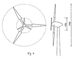
- Fig. 2 shows an embodiment that used to be often built in Denmark.
- Fig. 3 shows such a profile, which in the inner region of the rotor blade has been used.
- Even the cut-off profiles lead to large wind turbines (Rotor diameter over 70 m) but to blade depths of up to 6 m, which makes the transport of such rotor blades extremely difficult and their production extremely makes complicated.
- the object of the invention is to eliminate the aforementioned problems and the Manufacture of a wind turbine and to simplify their operation.
- the invention solves the problem with the features of a wind turbine Claim 1.
- Advantageous developments are described in the subclaims.
- the inventive concept of the wind turbine provides, the wind turbine equipped with two rotors, of which the first, the small rotor in front the second, the larger rotor, is arranged.
- the interior of the rotor of a wind turbine from Completely separate outside area.
- Such a wind turbine will be exemplified by the following figures described.
- As a description model here is a large wind turbine with a diameter of about 113 m and an installed generator power of about 5 MW.
- the rotor for the inner region has a diameter of about 40 m.
- the advantage of the wind turbine according to the invention lies in the fact that is suitable for the Inside of the rotor only a very small attack surface at high Setting wind speeds. This results in much lower extreme loads the entire wind turbine.
- the rotor blade for outdoor use (the second rotor) as a unit having a length of about 36.5 m can.
- Such a unit can be placed on a rotor blade stump, which aerodynamically no relevant amount to drive the rotor more guaranteed.
- the transport of the rotor blades is readily possible.
- Another advantage is also that the rotor blade adjustment of the second rotor does not need to be designed so large, since the rotor blade adjustment can be placed (stored) on the rotor blade stump and Therefore, about 20 m (radius of the small rotor) away from the hub.
- Each rotor drives its own generator during operation of the wind energy plant.
- the generator of the first rotor is located between the first and the second rotor and is preferably driven directly by this.
- Both rotors and both generators are from taken a single journal and are rotatably mounted on this.
- both rotors rotate in the same direction (clockwise), it is but also possible, the rotors with appropriate design of the rotor blades to turn in opposite directions.
- the tower of the wind turbine according to the invention has a height of more than 100 m, for example, the hub height is in the range of 120 to 160 m.
- the smaller rotor ensures that no aerodynamic hole is formed in the interior of the second rotor can.
Abstract
Description
Die Erfindung betrifft eine Windenergieantage, insbesondere eine Großwindenergieanlage mit einer Leistung von mehr als zwei MW, vorzugsweise von etwa fünf MW oder mehr.The invention relates to a Windenergieantage, in particular a large wind turbine with a power of more than two MW, preferably of about five MW or more.
Für eine solche Großwindenergieanlage wird erfindungsgemäß ein Rotorkonzept sowie die Ausbildung entsprechender Rotorblätter vorgeschlagen, damit der sichere Betrieb einer solchen Windenergieanlage möglich ist.For such a large wind turbine according to the invention a rotor concept as well as the training of appropriate rotor blades suggested, so that the safe Operation of such a wind turbine is possible.
Hierzu sei darauf hingewiesen, dass es bereits Stand der Technik ist DE-C-746 340 oder (Erich Hau, "Windkraftanlagen", 1996, 2. Auflage, Seite 113 ff) ein Rotorblatt, welches auf einen maximalen Wirkungsgrad optmiert wird, im Innenbereich mit sehr großen Blatttiefen auszustatten. Solche Rotorblätter sind beispielsweise von der Firma Enercon bei den Windenergieanlage vom Typ E-40 (Leistungsbereich liegt bei 500 bis 600 KW) im Einsatz. Der Innenbereich eines Rotorblattes ist dabei derjenige Teil, welcher nahe an der Nabe (Rotorblattwurzel) liegt und mithin über einen kleinen Radius verfügt.It should be noted that it is already prior art DE-C-746 340 or (Erich Hau, "Wind turbines", 1996, 2nd edition, page 113 ff) a rotor blade, which on maximum efficiency is optimized, indoors with very large To equip blade depths. Such rotor blades are for example from the company Enercon at the wind energy plant type E-40 (power range is 500 up to 600 KW) in use. The interior of a rotor blade is that part, which is close to the hub (rotor blade root) and therefore has a small Radius has.
Während ein solches auf maximalen Wirkungsgrad optimiertes Rotorblatt für kleinere Anlagen gut zu fertigen ist und auch problemlos transportiert werden kann, hat eine solches Rotorblattkonzept zwei Nachteile. Erstens erzeugt die sehr große Fläche des Rotorblattes an der Rotorblattwurzel bei hohen Windgeschwindigkeiten sehr hohe Lasten. Regelmäßig ist dann bereits die Windenergieanlage abgeschaltet. Für diese sehr hohen Lasten muss aber die gesamte Windenergieanlage ausgelegt (dimensioniert) werden. Der zweite Nachteil besteht in der Fertigung eines Rotorblatts mit sehr großer Blatttiefe. Während dieser Nachteil bei Rotorblättern mit einem kleineren Radius noch kaum ins Gewicht fällt, ist die Fertigung und der anschließende Transport eines solchen Rotorblattes, welches über eine sehr große Länge verfügt (z.B. mehr als 50 m), sehr kompliziert und teilweise unmöglich und die sehr große Blatttiefe bringt einen extrem großen Material- und Arbeitsmehraufwand mit sich.While such optimized for maximum efficiency rotor blade for smaller equipment is easy to manufacture and can also be easily transported, has such a rotor blade concept two disadvantages. First, the very large one generates Surface of the rotor blade at the rotor blade root at high wind speeds very high loads. Regularly then the wind turbine is already switched off. But for these very high loads, the entire wind turbine must be designed be (dimensioned). The second disadvantage is the production of a Rotor blade with very large blade depth. While this disadvantage with rotor blades with a smaller radius is still negligible, is the production and the subsequent transport of such a rotor blade, which has a very large Length has (for example, more than 50 m), very complicated and partly impossible and the very large blade depth brings an extremely large material and labor cost with himself.
Aus diesen Gründen wurde vorgeschlagen, die großen Blatttiefen zu umgehen. Fig. 2 zeigt eine Ausführung, die früher häufig in Dänemark gebaut wurde.For these reasons, it has been suggested to avoid the large blade depths. Fig. 2 shows an embodiment that used to be often built in Denmark.
Bei diesem Ausführungsbeispiel eines Rotorblattes wurde komplett auf den Innenbereich verzichtet. Da die Erntefläche der überstrichenen Rotorfläche entspricht, wurde angenommen, man könne auf diese sehr kleine Fläche (Innenbereichsfläche), die nur ca. 5 % der gesamten Fläche entspricht, verzichten oder den Rotordurchmesser geringfügig vergrößern, um somit den Flächenfluß auszugleichen.In this embodiment of a rotor blade was completely on the Interior omitted. As the harvested area of the swept rotor surface it was assumed that it would be possible to access this very small area (inner area), which corresponds to only about 5% of the total area, dispense or the Increase rotor diameter slightly to compensate for surface flow.
Hierbei wurde jedoch übersehen bzw. nicht darauf geachtet, dass damit im Nahbereich der Windenergieanlage mit Rotorblättern nach Fig. 2 ein aerodynamisches Loch entsteht. Der Wind kann im Nahbereich ungehindert durch dieses Loch hindurchströmen, ohne einen Widerstand zu erfahren. Das führt dazu, dass sich im Innenbereich (ersten Bereich des Rotors der Windenergieantage) des beginnenden Profils am Rotorblatt keine laminare Strömung aufbaut. Damit kann auch der erste Bereich des Rotorblattes mit (aktiver) Rotorprofilierung nicht zum Energieertrag beitragen.However, this was overlooked or not paid attention to the fact that in the Close range of the wind turbine with rotor blades according to Fig. 2 an aerodynamic Hole is created. The wind can move unhindered through this hole at close range flow through without experiencing resistance. That leads to being in the Indoor area (first area of the rotor of the wind energy plant) of the beginning Profils on the rotor blade no laminar flow builds up. So can the first Area of the rotor blade with (active) rotor profiling not for energy yield contribute.
Von der Firma Enercon wurde bereits sehr frühzeitig (ca. 1990) dicke, abgeschnittene Profile entwickelt, um die vorgenannten Probleme zu umgehen.From the company Enercon was already very early (about 1990) thick, cut off Profiles designed to circumvent the aforementioned problems.
Fig. 3 zeigt ein solches Profil, welches im inneren Bereich des Rotorblattes verwendet wurde. Selbst die abgeschnittenen Profile führen bei großen Windenergieanlagen (Rotordurchmesser über 70 m) jedoch zu Blatttiefen von bis zu 6 m, was den Transport solcher Rotorblätter extrem schwierig und ihre Fertigung äußerst aufwendig macht. Fig. 3 shows such a profile, which in the inner region of the rotor blade has been used. Even the cut-off profiles lead to large wind turbines (Rotor diameter over 70 m) but to blade depths of up to 6 m, which makes the transport of such rotor blades extremely difficult and their production extremely makes complicated.
Aufgabe der Erfindung ist es, die vorgenannten Probleme zu beseitigen und die Fertigung einer Windenergieanlage sowie deren Betrieb zu vereinfachen.The object of the invention is to eliminate the aforementioned problems and the Manufacture of a wind turbine and to simplify their operation.
Die Erfindung löst die Aufgabe mit den Merkmalen einer Windenergieanlage nach Anspruch 1. Vorteilhafte Weiterbildungen sind in den Unteransprüchen beschrieben.The invention solves the problem with the features of a wind turbine Claim 1. Advantageous developments are described in the subclaims.
Das erfindungsgemäße Konzept der Windenergieanlage sieht vor, die Windenergieanlage mit zwei Rotoren auszustatten, von denen der erste, der kleine Rotor vor dem zweiten, dem größeren Rotor, angeordnet ist. Mithin wird erfindungsgemäß vorgeschlagen, den Innenbereich des Rotors einer Windenergieanlage vom Außenbereich völlig zu trennen.The inventive concept of the wind turbine provides, the wind turbine equipped with two rotors, of which the first, the small rotor in front the second, the larger rotor, is arranged. Thus, according to the invention proposed, the interior of the rotor of a wind turbine from Completely separate outside area.
Eine solche Windenergieanlage wird anhand der nachfolgenden Figuren beispielhaft beschrieben. Als Beschreibungsmodell dient hierbei eine Großwindenergieanlage mit einem Durchmesser von etwa 113 m und einer installierten Generatorleistung von etwa 5 MW. Der Rotor für den inneren Bereich hat dabei einen Durchmesser von etwa 40 m.Such a wind turbine will be exemplified by the following figures described. As a description model here is a large wind turbine with a diameter of about 113 m and an installed generator power of about 5 MW. The rotor for the inner region has a diameter of about 40 m.
Damit verbleiben für den zweiten Rotor, den größeren Rotor, noch eine aktive Rotorblattlänge von etwa 36,5 m. Der erste, kleine Rotor dreht mit einen Nenndrehzahl von etwa 38 U/min. Der zweite, große Rotor dreht mit einer Nenndrehzahl von 11 U/min. Damit sind die Umfangsgeschwindigkeiten der Rotorblattspitzen beider Rotoren nahezu gleich.This leaves an active one for the second rotor, the larger rotor Rotor blade length of about 36.5 m. The first, small rotor rotates with one Rated speed of about 38 U / min. The second, big rotor turns with one Rated speed of 11 rpm. Thus, the peripheral speeds of the Rotor blade tips of both rotors almost the same.
Der Vorteil der erfindunsgemäßen Windenergieanlage liegt darin, dass sich für den Innenbereich des Rotors nur noch eine sehr kleine Angriffsfläche bei hohen Windgeschwindigkeiten einstellt. Damit ergeben sich sehr viel geringere Extremlasten der gesamten Windenergieanlage.The advantage of the wind turbine according to the invention lies in the fact that is suitable for the Inside of the rotor only a very small attack surface at high Setting wind speeds. This results in much lower extreme loads the entire wind turbine.
Ein weiterer Vorteil besteht darin, dass das Rotorblatt für den Außenbereich (der zweite Rotor) als eine Einheit mit einer Länge von etwa 36,5 m gefertigt werden kann. Eine solche Einheit kann auf einen Rotorblattstumpf aufgesetzt werden, welcher aerodynamisch keinen relevanten Betrag zum Antrieb des Rotors mehr leistet. Damit ist der Transport der Rotorblätter ohne weiteres möglich. Another advantage is that the rotor blade for outdoor use (the second rotor) as a unit having a length of about 36.5 m can. Such a unit can be placed on a rotor blade stump, which aerodynamically no relevant amount to drive the rotor more guaranteed. Thus, the transport of the rotor blades is readily possible.
Ein weiterer Vorteil besteht auch darin, dass die Rotorblattverstellvorrichtung des zweiten Rotors nicht mehr so groß ausgelegt werden muss, da die Rotorblattverstellvorrichtung auf den Rotorblattstumpf aufgesetzt (gelagert) werden kann und mithin etwa 20 m(Radius des kleinen Rotors) von der Nabe entfernt liegt.Another advantage is also that the rotor blade adjustment of the second rotor does not need to be designed so large, since the rotor blade adjustment can be placed (stored) on the rotor blade stump and Therefore, about 20 m (radius of the small rotor) away from the hub.
Jeder Rotor treibt im Betrieb der Windenergieanlage einen eigenen Generator an. Der Generator des ersten Rotors liegt zwischen dem ersten und dem zweiten Rotor und wird vorzugsweise direkt von diesem angetrieben. Für die Konstruktion der erfindungsgemäßen Windenergieanlage bedeutet dieses, dass vor den zweiten Rotor eine Rotor-Generator-Anordnung kleineren Typs, z.B. vom Typ E-40 der Firma Enercon, gesetzt wird. Beide Rotoren sowie beide Generatoren werden dabei von einem einzigen Achszapfen aufgenommen und sind drehbar auf diesem gelagert.Each rotor drives its own generator during operation of the wind energy plant. The generator of the first rotor is located between the first and the second rotor and is preferably driven directly by this. For the construction of the Wind turbine according to the invention this means that in front of the second rotor a rotor-generator arrangement of smaller type, e.g. Type E-40 of the company Enercon, is set. Both rotors and both generators are from taken a single journal and are rotatably mounted on this.
Vorzugsweise drehen beide Rotoren in die gleiche Richtung (rechtsdrehend), es ist aber auch möglich, die Rotoren bei entsprechender Auslegung der Rotorblätter gegensinnig drehen zu lassen.Preferably, both rotors rotate in the same direction (clockwise), it is but also possible, the rotors with appropriate design of the rotor blades to turn in opposite directions.
Der Turm der erfindungsgemäßen Windenergieanlage hat eine Höhe von mehr als 100 m, beispielsweise liegt die Nabenhöhe im Bereich von 120 bis 160 m.The tower of the wind turbine according to the invention has a height of more than 100 m, for example, the hub height is in the range of 120 to 160 m.
Im Betrieb der Windenergieanlage sorgt der kleinere Rotor (der erste Rotor) dafür, dass sich im Innenbereich des zweiten Rotors kein aerodynamisches Loch ausbilden kann.During operation of the wind turbine, the smaller rotor (the first rotor) ensures that no aerodynamic hole is formed in the interior of the second rotor can.
Claims (15)
- A wind power installation having at least two rotors arranged one behind the other, of which the first rotor, which is arranged in front of the second rotor, has a smaller diameter than the second rotor, characterised in that the rated speed of rotation of the first rotor is significantly higher than the rated speed of rotation of the second rotor and the peripheral speed of the rotor blade tips of both rotors is approximately the same in operation at normal rating.
- A wind power installation according to Claim 1, characterised in that the first rotor rotates at a higher speed than the second rotor.
- A wind power installation according to Claim 1 and 2, characterised in that the rated speed of rotation of the first rotor is approximately in the range between 25 and 45 rpm.
- A wind power installation according to Claim 1 and 2, characterised in that the rated speed of rotation of the second rotor is approximately in the range between 5 and 19 rpm.
- A wind power installation according to one of the preceding claims, characterised in that the peripheral speed of the rotor blade tips of both rotors is approximately the same in operation at normal rating.
- A wind power installation according to one of the preceding claims, characterised in that a respective generator is associated with each rotor.
- A wind power installation according to one of the preceding claims, characterised in that the first rotor has a diameter of approximately 35 to 55 m and the second rotor has a diameter of approximately 100 to 150 m, preferably approximately 113 m.
- A wind power installation having a first and a second rotor, the second rotor having a significantly larger diameter than the first rotor and being arranged behind the first rotor, and the second rotor having rotor blades whereof the active blade faces begin only in the region of the rotor blade tips of the first rotor.
- A wind power installation according to one of the preceding claims, characterised in that the second rotor has rotor blades comprising two parts, the second, outer part of the rotor blades forming the active rotor blade and the first part of the rotor blade being of an aerodynamic construction such that it makes no relevant contribution to driving the rotor.
- A wind power installation according to Claim 9, characterised in that a rotor blade servo device is constructed for a rotor blade of the second rotor and is constructed between the first and the second rotor blade parts.
- A wind power installation according to Claim 9 and 10, characterised in that the first rotor blade portion of the second rotor is rigidly secured to the hub of the second rotor.
- A wind power installation having a rotor arrangement which has a rotor inner region and a rotor outer region, the inner region of the rotor being separated from the outer region of the rotor.
- A wind power installation according to one of the preceding claims, characterised in that a first generator is arranged between the first rotor and the second rotor and the armature thereof is connected to the first rotor and driven thereby.
- A wind power installation according to one of the preceding claims, characterised in that the first rotor is arranged so closely in front of the second rotor that it is not possible for an aerodynamic gap to be formed in the region of the second rotor.
- A wind power installation according to one of the preceding claims, characterised in that both rotors turn in the same direction (clockwise).
Applications Claiming Priority (3)
| Application Number | Priority Date | Filing Date | Title |
|---|---|---|---|
| DE10003385A DE10003385A1 (en) | 2000-01-26 | 2000-01-26 | Wind turbine |
| DE10003385 | 2000-01-26 | ||
| PCT/EP2000/011218 WO2001055590A1 (en) | 2000-01-26 | 2000-11-14 | Wind power installation with two rotors in tandem |
Publications (2)
| Publication Number | Publication Date |
|---|---|
| EP1255931A1 EP1255931A1 (en) | 2002-11-13 |
| EP1255931B1 true EP1255931B1 (en) | 2005-06-29 |
Family
ID=7628824
Family Applications (1)
| Application Number | Title | Priority Date | Filing Date |
|---|---|---|---|
| EP00974529A Expired - Lifetime EP1255931B1 (en) | 2000-01-26 | 2000-11-14 | Wind power installation with two rotors in tandem |
Country Status (13)
| Country | Link |
|---|---|
| US (1) | US7074011B1 (en) |
| EP (1) | EP1255931B1 (en) |
| JP (2) | JP2003526757A (en) |
| KR (2) | KR20020067935A (en) |
| AT (1) | ATE298840T1 (en) |
| AU (1) | AU758742B2 (en) |
| BR (1) | BR0017014B1 (en) |
| CA (1) | CA2395612C (en) |
| DE (2) | DE10003385A1 (en) |
| DK (1) | DK1255931T3 (en) |
| ES (1) | ES2242647T3 (en) |
| PT (1) | PT1255931E (en) |
| WO (1) | WO2001055590A1 (en) |
Cited By (1)
| Publication number | Priority date | Publication date | Assignee | Title |
|---|---|---|---|---|
| DE102019111123A1 (en) * | 2019-04-30 | 2020-11-05 | Wobben Properties Gmbh | Rotor for a wind turbine and wind turbine |
Families Citing this family (37)
| Publication number | Priority date | Publication date | Assignee | Title |
|---|---|---|---|---|
| AU2002316786A1 (en) * | 2002-05-17 | 2003-12-02 | Vestas Wind Systems A/S | Wind turbine rotor construction |
| KR20070063610A (en) | 2002-06-05 | 2007-06-19 | 알로이즈 우벤 | Rotor blade for a wind power plant |
| DE10319246A1 (en) | 2003-04-28 | 2004-12-16 | Aloys Wobben | Rotor blade of a wind turbine |
| CA2477595A1 (en) * | 2004-08-23 | 2006-02-23 | Alfred L. Mathieu | An auxiliary propeller rotor for horizontal wind turbine generators |
| GB2440464B (en) * | 2005-03-23 | 2010-08-11 | Gu Duck Hong | Windmill-type electric generation system |
| DE102005023120B3 (en) * | 2005-05-19 | 2006-11-16 | Möhring, Manfred, Dr.rer.nat. | Two stage wind power plant to produce electricity has second annular carrier element of second wind power unit of diameter not less than that of first one |
| GB0516149D0 (en) * | 2005-08-05 | 2005-09-14 | Univ Strathclyde | Turbine |
| DK176317B1 (en) | 2005-10-17 | 2007-07-30 | Lm Glasfiber As | Blade for a rotor on a wind turbine |
| US20070205603A1 (en) * | 2006-03-03 | 2007-09-06 | Karl Appa | Methods and devices for improving efficiency of wind turbines in low wind speed sites |
| EP2107235A1 (en) * | 2008-04-02 | 2009-10-07 | Lm Glasfiber A/S | A wind turbine blade with an auxiliary airfoil |
| CN101457736A (en) * | 2008-09-05 | 2009-06-17 | 张云龙 | Composite rotor system of wind motor |
| EA016290B1 (en) * | 2008-12-01 | 2012-03-30 | Омир Каримович БАЯЛИЕВ | Wind electric generating plant |
| WO2010087178A1 (en) * | 2009-01-30 | 2010-08-05 | 国立大学法人九州工業大学 | Wind turbine generator |
| EP2417351A2 (en) | 2009-04-06 | 2012-02-15 | Peter V. Bitar | Coaxial wind turbine |
| GB0908355D0 (en) * | 2009-05-15 | 2009-06-24 | Bailey Ralph Peter S | Wind turbine diffuser |
| US20110076145A1 (en) * | 2009-09-29 | 2011-03-31 | Hong Chen-Ming | High efficient compounded wind power system |
| KR100962774B1 (en) * | 2009-11-09 | 2010-06-10 | 강현문 | Wind power generator |
| US20110204648A1 (en) * | 2009-12-14 | 2011-08-25 | Wilson Roger D | Windmill with blades with passageways from hub to tip |
| KR101205329B1 (en) * | 2010-06-11 | 2012-11-28 | 신익 | Wind Power Generator Having Triple Rotors Integrated System |
| US8240995B2 (en) * | 2010-12-20 | 2012-08-14 | General Electric Company | Wind turbine, aerodynamic assembly for use in a wind turbine, and method for assembling thereof |
| US8678767B2 (en) | 2011-04-08 | 2014-03-25 | Peter Mok | Wind turbine |
| US8308437B2 (en) * | 2011-04-26 | 2012-11-13 | General Electric Company | Wind turbine with auxiliary fins |
| KR101388494B1 (en) * | 2012-10-24 | 2014-04-23 | 두산중공업 주식회사 | Mult type wind turbine |
| EP2780583B1 (en) | 2011-11-17 | 2016-09-07 | Doosan Heavy Industries & Construction Co., Ltd. | Wind turbine with multiple nacelles |
| US20130136601A1 (en) * | 2011-11-25 | 2013-05-30 | Robert Stephen Watral | Large Contra-Rotating Wind Turbine |
| US10030628B2 (en) | 2012-05-24 | 2018-07-24 | Thunderbird Power Corp | Horizontal axis wind machine with multiple rotors |
| JP5946812B2 (en) * | 2013-10-31 | 2016-07-06 | 三菱重工業株式会社 | Wind turbine rotor and wind power generator |
| GB2539237B (en) | 2015-06-10 | 2020-12-09 | Equinor Asa | Rotor blade shaped to enhance wake diffusion |
| WO2016203046A1 (en) * | 2015-06-18 | 2016-12-22 | New World Energy Enterprises Ltd | A wind turbine with rotating augmentor |
| US10066597B2 (en) * | 2016-12-14 | 2018-09-04 | Thunderbird Power Corp | Multiple-blade wind machine with shrouded rotors |
| DE102017124861A1 (en) | 2017-10-24 | 2019-04-25 | Wobben Properties Gmbh | Rotor blade of a wind turbine and method for its design |
| CN107882678B (en) * | 2017-11-13 | 2018-09-14 | 扬州大学 | A kind of improved level axis wind energy conversion system and its application method, design method |
| CA3110574A1 (en) * | 2018-09-04 | 2020-03-12 | Biomerenewables Inc. | Fluidic turbine structure |
| JP6677783B1 (en) * | 2018-10-23 | 2020-04-08 | 三菱電機エンジニアリング株式会社 | Propeller device |
| JP6805298B1 (en) * | 2019-07-23 | 2020-12-23 | 三菱電機エンジニアリング株式会社 | Small windmill device |
| CN113775470A (en) * | 2021-09-23 | 2021-12-10 | 中国华能集团清洁能源技术研究院有限公司 | Wind wheel wind turbine generator and fan blade thereof |
| CN114576082B (en) * | 2022-03-18 | 2023-05-02 | 中国华能集团清洁能源技术研究院有限公司 | Wind power generation device |
Family Cites Families (20)
| Publication number | Priority date | Publication date | Assignee | Title |
|---|---|---|---|---|
| US1498978A (en) * | 1921-11-10 | 1924-06-24 | Muntz William Edgar | Windmill and the like |
| FR627371A (en) | 1926-01-12 | 1927-10-03 | Inst Voor Aero En Hydro Dynami | Device to facilitate the start-up of flow-driven machines |
| US1804016A (en) | 1929-06-12 | 1931-05-05 | Koenig Remus | Propeller |
| US2177801A (en) * | 1937-02-04 | 1939-10-31 | Erren Rudolf Arnold | Electric generator |
| DE746340C (en) | 1937-03-07 | 1944-07-29 | Hermann Honnef | Large wind power plant with main wind turbines lying one behind the other on the same axis and an auxiliary wind turbine connected upstream |
| LU33506A1 (en) * | 1953-12-23 | 1900-01-01 | ||
| DE2547503A1 (en) | 1975-10-21 | 1977-04-28 | Brockmann Hans Joachim Prof Dr | Double impeller wind power unit - has higher speed small impeller geared to lower speed larger impeller to produce sum output |
| US4039848A (en) * | 1975-11-10 | 1977-08-02 | Winderl William R | Wind operated generator |
| US4065225A (en) | 1976-04-22 | 1977-12-27 | Allison William D | Multivane windmill |
| US4217501A (en) * | 1977-10-11 | 1980-08-12 | Allison William D | Mounting for windmills |
| US4345161A (en) * | 1979-02-23 | 1982-08-17 | George Crompton | Multi-wheel windmill electro-generator |
| DE2932293A1 (en) | 1979-08-09 | 1981-02-26 | Rudolf Arnold Erren | Wind powered plant with counter-rotating propellers - ensures constant rotational speed relationship, resulting in generator being driven at optimum value |
| US4299198A (en) * | 1979-09-17 | 1981-11-10 | Woodhull William M | Wind power conversion and control system |
| JPS56138465A (en) * | 1980-03-31 | 1981-10-29 | Matsushita Electric Works Ltd | Propeller windmill |
| DE3018802A1 (en) | 1980-05-16 | 1981-11-26 | Fritz-Helmut 3050 Wunstorf Namendorf | Garden reclining chair self-assembled from rectangular plastics units - each with stiffening flanges and corner legs and simple push on connectors |
| DE3117996A1 (en) | 1981-05-07 | 1982-11-25 | Ficht GmbH, 8011 Kirchseeon | Wind power plant |
| US4447738A (en) * | 1981-12-30 | 1984-05-08 | Allison Johnny H | Wind power electrical generator system |
| KR960007401B1 (en) | 1994-06-27 | 1996-05-31 | 신찬 | Multi-unit rotor blade system integrated wind turbine |
| DE4444757A1 (en) | 1994-12-15 | 1996-06-20 | Lehmann Klaus Dieter | Wind-powered generator/blower arrangement |
| JPH1162811A (en) * | 1997-08-11 | 1999-03-05 | Akiji Matoba | Wind-mill generating device using wind power repeatedly and strong-wind intercepting device |
-
2000
- 2000-01-26 DE DE10003385A patent/DE10003385A1/en not_active Withdrawn
- 2000-11-14 DK DK00974529T patent/DK1255931T3/en active
- 2000-11-14 EP EP00974529A patent/EP1255931B1/en not_active Expired - Lifetime
- 2000-11-14 KR KR1020027009390A patent/KR20020067935A/en active Application Filing
- 2000-11-14 KR KR1020057022864A patent/KR20050116909A/en not_active Application Discontinuation
- 2000-11-14 WO PCT/EP2000/011218 patent/WO2001055590A1/en active IP Right Grant
- 2000-11-14 CA CA002395612A patent/CA2395612C/en not_active Expired - Lifetime
- 2000-11-14 ES ES00974529T patent/ES2242647T3/en not_active Expired - Lifetime
- 2000-11-14 DE DE50010649T patent/DE50010649D1/en not_active Expired - Lifetime
- 2000-11-14 BR BRPI0017014-3A patent/BR0017014B1/en not_active IP Right Cessation
- 2000-11-14 AU AU12797/01A patent/AU758742B2/en not_active Ceased
- 2000-11-14 AT AT00974529T patent/ATE298840T1/en active
- 2000-11-14 PT PT00974529T patent/PT1255931E/en unknown
- 2000-11-14 JP JP2001555696A patent/JP2003526757A/en active Pending
- 2000-11-14 US US10/182,281 patent/US7074011B1/en not_active Expired - Lifetime
-
2006
- 2006-03-20 JP JP2006076551A patent/JP2006177370A/en active Pending
Cited By (2)
| Publication number | Priority date | Publication date | Assignee | Title |
|---|---|---|---|---|
| DE102019111123A1 (en) * | 2019-04-30 | 2020-11-05 | Wobben Properties Gmbh | Rotor for a wind turbine and wind turbine |
| WO2020221860A1 (en) | 2019-04-30 | 2020-11-05 | Wobben Properties Gmbh | Rotor for a wind turbine and wind turbine |
Also Published As
| Publication number | Publication date |
|---|---|
| DK1255931T3 (en) | 2005-10-17 |
| CA2395612C (en) | 2004-06-22 |
| KR20020067935A (en) | 2002-08-24 |
| JP2006177370A (en) | 2006-07-06 |
| DE50010649D1 (en) | 2005-08-04 |
| PT1255931E (en) | 2005-08-31 |
| AU1279701A (en) | 2001-08-07 |
| EP1255931A1 (en) | 2002-11-13 |
| BR0017014A (en) | 2002-10-22 |
| ATE298840T1 (en) | 2005-07-15 |
| WO2001055590A1 (en) | 2001-08-02 |
| BR0017014B1 (en) | 2009-01-13 |
| ES2242647T3 (en) | 2005-11-16 |
| AU758742B2 (en) | 2003-03-27 |
| KR20050116909A (en) | 2005-12-13 |
| US7074011B1 (en) | 2006-07-11 |
| CA2395612A1 (en) | 2001-08-02 |
| DE10003385A1 (en) | 2001-08-02 |
| JP2003526757A (en) | 2003-09-09 |
Similar Documents
| Publication | Publication Date | Title |
|---|---|---|
| EP1255931B1 (en) | Wind power installation with two rotors in tandem | |
| DE60010843T2 (en) | WIND TURBINE WITH COMMON ROTORS | |
| EP2655874B1 (en) | Wind-powered rotor and power generation method therewith | |
| DE102014002078B4 (en) | Vertical Wind Generator | |
| DE102008025719B4 (en) | Wind turbine | |
| EP3677771A1 (en) | Vertical wind turbine | |
| EP1387954B1 (en) | Wind turbine comprising a vertical axis | |
| WO2023001864A1 (en) | Flow power plant having pivoting blades | |
| EP2425124A2 (en) | Underwater power plant comprising a water turbine with bidirectional fluid flow and unidirectional rotation | |
| WO2013190117A1 (en) | Rotor for a vertical-axis wind turbine | |
| DE202012000907U1 (en) | Flow turbine | |
| EP2699797B1 (en) | Wind turbine | |
| DE102010016086A1 (en) | Rotor blade for H rotor | |
| EP2636892A2 (en) | Wind power plant and method for generating of rotary energy from wind | |
| DE102006050498B3 (en) | Wind power installation, has rotor head with three bladed propeller with upstream single-arm blade are built one behind other on assembly shaft, and hollow shafts that are provided with gear wheel | |
| DE3230072C2 (en) | Wind turbine | |
| DE102008051297B3 (en) | Rotor blade of a wind turbine | |
| DE202018003498U1 (en) | Length-variable H-Darrieus rotor | |
| WO2012156352A1 (en) | Wind turbine system | |
| DE102009008805A1 (en) | Wind turbine for use in generation of power, has vane whose surface is formed such that counter torque is less around vertical yaw axis by wind effect on vane and lesser than torque around yaw axis by wind effect on wind wheel | |
| DE102010008379A1 (en) | Device for use in wind power plant for converting kinetic energy of flowing gaseous or liquid medium into kinetic rotation energy, comprises axis of rotation, which is formed in form of individual or two rotating axes | |
| DE8228078U1 (en) | VERTICAL AXIS ROTOR | |
| DE10133456A1 (en) | Wind wheel for a wind power facility, has wind wheel rotor on mast with a rotor shaft and rotor blades running in an axial direction, forming an increased resistance rotor and interlinking via endless feeder surfaces. | |
| DE202022105938U1 (en) | wind turbine | |
| WO2023274946A1 (en) | Rotor for a wind turbine and method for operating a wind turbine |
Legal Events
| Date | Code | Title | Description |
|---|---|---|---|
| PUAI | Public reference made under article 153(3) epc to a published international application that has entered the european phase |
Free format text: ORIGINAL CODE: 0009012 |
|
| 17P | Request for examination filed |
Effective date: 20020826 |
|
| AK | Designated contracting states |
Kind code of ref document: A1 Designated state(s): AT BE CH CY DE DK ES FI FR GB GR IE IT LI LU MC NL PT SE TR |
|
| AX | Request for extension of the european patent |
Free format text: AL;LT;LV;MK;RO;SI |
|
| GRAP | Despatch of communication of intention to grant a patent |
Free format text: ORIGINAL CODE: EPIDOSNIGR1 |
|
| GRAS | Grant fee paid |
Free format text: ORIGINAL CODE: EPIDOSNIGR3 |
|
| GRAA | (expected) grant |
Free format text: ORIGINAL CODE: 0009210 |
|
| AK | Designated contracting states |
Kind code of ref document: B1 Designated state(s): AT BE CH CY DE DK ES FI FR GB GR IE IT LI LU MC NL PT SE TR |
|
| REG | Reference to a national code |
Ref country code: GB Ref legal event code: FG4D Free format text: NOT ENGLISH |
|
| REG | Reference to a national code |
Ref country code: CH Ref legal event code: EP |
|
| REF | Corresponds to: |
Ref document number: 50010649 Country of ref document: DE Date of ref document: 20050804 Kind code of ref document: P |
|
| REG | Reference to a national code |
Ref country code: IE Ref legal event code: FG4D Free format text: LANGUAGE OF EP DOCUMENT: GERMAN |
|
| REG | Reference to a national code |
Ref country code: PT Ref legal event code: SC4A Effective date: 20050707 Ref country code: CH Ref legal event code: NV Representative=s name: ZIMMERLI, WAGNER & PARTNER AG |
|
| REG | Reference to a national code |
Ref country code: GR Ref legal event code: EP Ref document number: 20050402393 Country of ref document: GR |
|
| REG | Reference to a national code |
Ref country code: DK Ref legal event code: T3 |
|
| REG | Reference to a national code |
Ref country code: SE Ref legal event code: TRGR |
|
| GBT | Gb: translation of ep patent filed (gb section 77(6)(a)/1977) |
Effective date: 20050928 |
|
| REG | Reference to a national code |
Ref country code: ES Ref legal event code: FG2A Ref document number: 2242647 Country of ref document: ES Kind code of ref document: T3 |
|
| PG25 | Lapsed in a contracting state [announced via postgrant information from national office to epo] |
Ref country code: MC Free format text: LAPSE BECAUSE OF NON-PAYMENT OF DUE FEES Effective date: 20051130 |
|
| ET | Fr: translation filed | ||
| PLBE | No opposition filed within time limit |
Free format text: ORIGINAL CODE: 0009261 |
|
| STAA | Information on the status of an ep patent application or granted ep patent |
Free format text: STATUS: NO OPPOSITION FILED WITHIN TIME LIMIT |
|
| 26N | No opposition filed |
Effective date: 20060330 |
|
| REG | Reference to a national code |
Ref country code: CH Ref legal event code: PFA Owner name: WOBBEN, ALOYS Free format text: WOBBEN, ALOYS#ARGESTRASSE 19#26607 AURICH (DE) -TRANSFER TO- WOBBEN, ALOYS#ARGESTRASSE 19#26607 AURICH (DE) |
|
| REG | Reference to a national code |
Ref country code: CH Ref legal event code: NV Representative=s name: WAGNER PATENT AG, CH |
|
| REG | Reference to a national code |
Ref country code: FR Ref legal event code: PLFP Year of fee payment: 16 |
|
| REG | Reference to a national code |
Ref country code: FR Ref legal event code: PLFP Year of fee payment: 17 |
|
| REG | Reference to a national code |
Ref country code: FR Ref legal event code: PLFP Year of fee payment: 18 |
|
| PGFP | Annual fee paid to national office [announced via postgrant information from national office to epo] |
Ref country code: LU Payment date: 20171122 Year of fee payment: 18 |
|
| PGFP | Annual fee paid to national office [announced via postgrant information from national office to epo] |
Ref country code: TR Payment date: 20171113 Year of fee payment: 18 Ref country code: FI Payment date: 20171117 Year of fee payment: 18 |
|
| PGFP | Annual fee paid to national office [announced via postgrant information from national office to epo] |
Ref country code: IT Payment date: 20171122 Year of fee payment: 18 Ref country code: CH Payment date: 20171124 Year of fee payment: 18 Ref country code: GR Payment date: 20171121 Year of fee payment: 18 Ref country code: IE Payment date: 20171123 Year of fee payment: 18 Ref country code: BE Payment date: 20171122 Year of fee payment: 18 |
|
| PGFP | Annual fee paid to national office [announced via postgrant information from national office to epo] |
Ref country code: CY Payment date: 20171109 Year of fee payment: 18 |
|
| REG | Reference to a national code |
Ref country code: CH Ref legal event code: PL |
|
| PG25 | Lapsed in a contracting state [announced via postgrant information from national office to epo] |
Ref country code: LU Free format text: LAPSE BECAUSE OF NON-PAYMENT OF DUE FEES Effective date: 20181114 Ref country code: CY Free format text: LAPSE BECAUSE OF NON-PAYMENT OF DUE FEES Effective date: 20181114 Ref country code: FI Free format text: LAPSE BECAUSE OF NON-PAYMENT OF DUE FEES Effective date: 20181114 |
|
| REG | Reference to a national code |
Ref country code: BE Ref legal event code: MM Effective date: 20181130 |
|
| REG | Reference to a national code |
Ref country code: IE Ref legal event code: MM4A |
|
| PG25 | Lapsed in a contracting state [announced via postgrant information from national office to epo] |
Ref country code: GR Free format text: LAPSE BECAUSE OF NON-PAYMENT OF DUE FEES Effective date: 20190605 Ref country code: LI Free format text: LAPSE BECAUSE OF NON-PAYMENT OF DUE FEES Effective date: 20181130 Ref country code: CH Free format text: LAPSE BECAUSE OF NON-PAYMENT OF DUE FEES Effective date: 20181130 |
|
| PG25 | Lapsed in a contracting state [announced via postgrant information from national office to epo] |
Ref country code: IT Free format text: LAPSE BECAUSE OF NON-PAYMENT OF DUE FEES Effective date: 20181114 Ref country code: IE Free format text: LAPSE BECAUSE OF NON-PAYMENT OF DUE FEES Effective date: 20181114 |
|
| PG25 | Lapsed in a contracting state [announced via postgrant information from national office to epo] |
Ref country code: BE Free format text: LAPSE BECAUSE OF NON-PAYMENT OF DUE FEES Effective date: 20181130 |
|
| PGFP | Annual fee paid to national office [announced via postgrant information from national office to epo] |
Ref country code: NL Payment date: 20191121 Year of fee payment: 20 Ref country code: DE Payment date: 20191206 Year of fee payment: 20 Ref country code: SE Payment date: 20191125 Year of fee payment: 20 Ref country code: PT Payment date: 20191112 Year of fee payment: 20 |
|
| PGFP | Annual fee paid to national office [announced via postgrant information from national office to epo] |
Ref country code: DK Payment date: 20191121 Year of fee payment: 20 Ref country code: ES Payment date: 20191216 Year of fee payment: 20 Ref country code: FR Payment date: 20191121 Year of fee payment: 20 |
|
| PGFP | Annual fee paid to national office [announced via postgrant information from national office to epo] |
Ref country code: AT Payment date: 20191119 Year of fee payment: 20 |
|
| PGFP | Annual fee paid to national office [announced via postgrant information from national office to epo] |
Ref country code: GB Payment date: 20191121 Year of fee payment: 20 |
|
| REG | Reference to a national code |
Ref country code: DE Ref legal event code: R071 Ref document number: 50010649 Country of ref document: DE |
|
| REG | Reference to a national code |
Ref country code: DK Ref legal event code: EUP Expiry date: 20201114 |
|
| REG | Reference to a national code |
Ref country code: NL Ref legal event code: MK Effective date: 20201113 |
|
| REG | Reference to a national code |
Ref country code: GB Ref legal event code: PE20 Expiry date: 20201113 |
|
| REG | Reference to a national code |
Ref country code: AT Ref legal event code: MK07 Ref document number: 298840 Country of ref document: AT Kind code of ref document: T Effective date: 20201114 |
|
| PG25 | Lapsed in a contracting state [announced via postgrant information from national office to epo] |
Ref country code: PT Free format text: LAPSE BECAUSE OF EXPIRATION OF PROTECTION Effective date: 20201125 Ref country code: GB Free format text: LAPSE BECAUSE OF EXPIRATION OF PROTECTION Effective date: 20201113 |
|
| REG | Reference to a national code |
Ref country code: ES Ref legal event code: FD2A Effective date: 20210226 |
|
| PG25 | Lapsed in a contracting state [announced via postgrant information from national office to epo] |
Ref country code: ES Free format text: LAPSE BECAUSE OF EXPIRATION OF PROTECTION Effective date: 20201115 |
|
| PG25 | Lapsed in a contracting state [announced via postgrant information from national office to epo] |
Ref country code: TR Free format text: LAPSE BECAUSE OF FAILURE TO SUBMIT A TRANSLATION OF THE DESCRIPTION OR TO PAY THE FEE WITHIN THE PRESCRIBED TIME-LIMIT Effective date: 20050629 |