EP1255931B1 - Windenergieanlage mit zwei hintereinander angeordneten rotoren - Google Patents
Windenergieanlage mit zwei hintereinander angeordneten rotoren Download PDFInfo
- Publication number
- EP1255931B1 EP1255931B1 EP00974529A EP00974529A EP1255931B1 EP 1255931 B1 EP1255931 B1 EP 1255931B1 EP 00974529 A EP00974529 A EP 00974529A EP 00974529 A EP00974529 A EP 00974529A EP 1255931 B1 EP1255931 B1 EP 1255931B1
- Authority
- EP
- European Patent Office
- Prior art keywords
- rotor
- wind power
- power installation
- installation according
- blade
- Prior art date
- Legal status (The legal status is an assumption and is not a legal conclusion. Google has not performed a legal analysis and makes no representation as to the accuracy of the status listed.)
- Expired - Lifetime
Links
- 238000009434 installation Methods 0.000 title claims abstract 17
- 230000002093 peripheral effect Effects 0.000 claims description 3
- 238000010276 construction Methods 0.000 claims description 2
- 238000004519 manufacturing process Methods 0.000 description 5
- 238000011161 development Methods 0.000 description 1
- 230000018109 developmental process Effects 0.000 description 1
Images

Classifications
-
- F—MECHANICAL ENGINEERING; LIGHTING; HEATING; WEAPONS; BLASTING
- F03—MACHINES OR ENGINES FOR LIQUIDS; WIND, SPRING, OR WEIGHT MOTORS; PRODUCING MECHANICAL POWER OR A REACTIVE PROPULSIVE THRUST, NOT OTHERWISE PROVIDED FOR
- F03D—WIND MOTORS
- F03D1/00—Wind motors with rotation axis substantially parallel to the air flow entering the rotor
- F03D1/02—Wind motors with rotation axis substantially parallel to the air flow entering the rotor having a plurality of rotors
- F03D1/025—Wind motors with rotation axis substantially parallel to the air flow entering the rotor having a plurality of rotors coaxially arranged
-
- F—MECHANICAL ENGINEERING; LIGHTING; HEATING; WEAPONS; BLASTING
- F03—MACHINES OR ENGINES FOR LIQUIDS; WIND, SPRING, OR WEIGHT MOTORS; PRODUCING MECHANICAL POWER OR A REACTIVE PROPULSIVE THRUST, NOT OTHERWISE PROVIDED FOR
- F03D—WIND MOTORS
- F03D1/00—Wind motors with rotation axis substantially parallel to the air flow entering the rotor
- F03D1/06—Rotors
- F03D1/0608—Rotors characterised by their aerodynamic shape
- F03D1/0633—Rotors characterised by their aerodynamic shape of the blades
-
- F—MECHANICAL ENGINEERING; LIGHTING; HEATING; WEAPONS; BLASTING
- F03—MACHINES OR ENGINES FOR LIQUIDS; WIND, SPRING, OR WEIGHT MOTORS; PRODUCING MECHANICAL POWER OR A REACTIVE PROPULSIVE THRUST, NOT OTHERWISE PROVIDED FOR
- F03D—WIND MOTORS
- F03D1/00—Wind motors with rotation axis substantially parallel to the air flow entering the rotor
- F03D1/06—Rotors
- F03D1/065—Rotors characterised by their construction elements
- F03D1/0675—Rotors characterised by their construction elements of the blades
-
- F—MECHANICAL ENGINEERING; LIGHTING; HEATING; WEAPONS; BLASTING
- F03—MACHINES OR ENGINES FOR LIQUIDS; WIND, SPRING, OR WEIGHT MOTORS; PRODUCING MECHANICAL POWER OR A REACTIVE PROPULSIVE THRUST, NOT OTHERWISE PROVIDED FOR
- F03D—WIND MOTORS
- F03D9/00—Adaptations of wind motors for special use; Combinations of wind motors with apparatus driven thereby; Wind motors specially adapted for installation in particular locations
- F03D9/20—Wind motors characterised by the driven apparatus
- F03D9/25—Wind motors characterised by the driven apparatus the apparatus being an electrical generator
-
- F—MECHANICAL ENGINEERING; LIGHTING; HEATING; WEAPONS; BLASTING
- F05—INDEXING SCHEMES RELATING TO ENGINES OR PUMPS IN VARIOUS SUBCLASSES OF CLASSES F01-F04
- F05B—INDEXING SCHEME RELATING TO WIND, SPRING, WEIGHT, INERTIA OR LIKE MOTORS, TO MACHINES OR ENGINES FOR LIQUIDS COVERED BY SUBCLASSES F03B, F03D AND F03G
- F05B2240/00—Components
- F05B2240/20—Rotors
- F05B2240/21—Rotors for wind turbines
- F05B2240/221—Rotors for wind turbines with horizontal axis
-
- Y—GENERAL TAGGING OF NEW TECHNOLOGICAL DEVELOPMENTS; GENERAL TAGGING OF CROSS-SECTIONAL TECHNOLOGIES SPANNING OVER SEVERAL SECTIONS OF THE IPC; TECHNICAL SUBJECTS COVERED BY FORMER USPC CROSS-REFERENCE ART COLLECTIONS [XRACs] AND DIGESTS
- Y02—TECHNOLOGIES OR APPLICATIONS FOR MITIGATION OR ADAPTATION AGAINST CLIMATE CHANGE
- Y02E—REDUCTION OF GREENHOUSE GAS [GHG] EMISSIONS, RELATED TO ENERGY GENERATION, TRANSMISSION OR DISTRIBUTION
- Y02E10/00—Energy generation through renewable energy sources
- Y02E10/70—Wind energy
- Y02E10/72—Wind turbines with rotation axis in wind direction
-
- Y—GENERAL TAGGING OF NEW TECHNOLOGICAL DEVELOPMENTS; GENERAL TAGGING OF CROSS-SECTIONAL TECHNOLOGIES SPANNING OVER SEVERAL SECTIONS OF THE IPC; TECHNICAL SUBJECTS COVERED BY FORMER USPC CROSS-REFERENCE ART COLLECTIONS [XRACs] AND DIGESTS
- Y02—TECHNOLOGIES OR APPLICATIONS FOR MITIGATION OR ADAPTATION AGAINST CLIMATE CHANGE
- Y02P—CLIMATE CHANGE MITIGATION TECHNOLOGIES IN THE PRODUCTION OR PROCESSING OF GOODS
- Y02P70/00—Climate change mitigation technologies in the production process for final industrial or consumer products
- Y02P70/50—Manufacturing or production processes characterised by the final manufactured product
Definitions
- the invention relates to a Windenergyantage, in particular a large wind turbine with a power of more than two MW, preferably of about five MW or more.
- Fig. 2 shows an embodiment that used to be often built in Denmark.
- Fig. 3 shows such a profile, which in the inner region of the rotor blade has been used.
- Even the cut-off profiles lead to large wind turbines (Rotor diameter over 70 m) but to blade depths of up to 6 m, which makes the transport of such rotor blades extremely difficult and their production extremely makes complicated.
- the object of the invention is to eliminate the aforementioned problems and the Manufacture of a wind turbine and to simplify their operation.
- the invention solves the problem with the features of a wind turbine Claim 1.
- Advantageous developments are described in the subclaims.
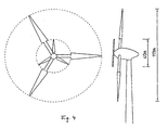
- the inventive concept of the wind turbine provides, the wind turbine equipped with two rotors, of which the first, the small rotor in front the second, the larger rotor, is arranged.
- the interior of the rotor of a wind turbine from Completely separate outside area.
- Such a wind turbine will be exemplified by the following figures described.
- As a description model here is a large wind turbine with a diameter of about 113 m and an installed generator power of about 5 MW.
- the rotor for the inner region has a diameter of about 40 m.
- the advantage of the wind turbine according to the invention lies in the fact that is suitable for the Inside of the rotor only a very small attack surface at high Setting wind speeds. This results in much lower extreme loads the entire wind turbine.
- the rotor blade for outdoor use (the second rotor) as a unit having a length of about 36.5 m can.
- Such a unit can be placed on a rotor blade stump, which aerodynamically no relevant amount to drive the rotor more guaranteed.
- the transport of the rotor blades is readily possible.
- Another advantage is also that the rotor blade adjustment of the second rotor does not need to be designed so large, since the rotor blade adjustment can be placed (stored) on the rotor blade stump and Therefore, about 20 m (radius of the small rotor) away from the hub.
- Each rotor drives its own generator during operation of the wind energy plant.
- the generator of the first rotor is located between the first and the second rotor and is preferably driven directly by this.
- Both rotors and both generators are from taken a single journal and are rotatably mounted on this.
- both rotors rotate in the same direction (clockwise), it is but also possible, the rotors with appropriate design of the rotor blades to turn in opposite directions.
- the tower of the wind turbine according to the invention has a height of more than 100 m, for example, the hub height is in the range of 120 to 160 m.
- the smaller rotor ensures that no aerodynamic hole is formed in the interior of the second rotor can.
Description
Claims (15)
- Windenergieanlangen mit wenigstens zwei hintereinander angeordneten Rotoren, von den der erste Rotor, der vor dem zweiten Rotor angeordnet ist, einen kleineren Durchmesser aufweist als der zweite Rotor
dadurch gekennzeichnet, dass die Nenndrehzahl des ersten Rotors deutlich höher ist als die Nenndrehzahl des zweiten Rotors und die Umfangsgeschwindigkeit der Rotorblattspitzen beider Rotoren im Nennbetrieb nahezu gleich ist. - Windenergieanlage nach Anspruch 1,
dadurch gekennzeichnet, dass der erste Rotor mit einer höheren Drehzahl rotiert, als der zweite Rotor. - Windenergieanlage nach Anspruch 1 und 2,
dadurch gekennzeichnet, dass die Nenndrehzahl des ersten Rotors etwa im Bereich von 25 bis 45 U/min. liegt. - Windenergieantage nach Anspruch 1 und 2,
dadurch gekennzeichnet, dass die Nenndrehzahl des zweiten Rotors etwa im Bereich von 5 bis 19 U/min. liegt. - Windenergieanlage nach einem der vorhergehenden Ansprüche,
dadurch gekennzeichnet, dass die Umfangsgeschwindigkeit der Rotorblattspitzen beider Rotoren im Nennbetrieb nahezu gleich, ist. - Windenergieanlage nach einem der vorhergehenden Ansprüche,
dadurch gekennzeichnet, dass jedem Rotor jeweils ein Generator zugeordnet ist. - Windenergieantage nach einem der vorhergehenden Ansprüche,
dadurch gekennzeichnet, dass der erste Rotor einen Durchmesser von etwa 35 bis 55 m und der zweite Rotor einen Durchmesser von etwa 100 bis 150 m, vorzugsweise etwa 113 m, aufweist. - Windenergieanlage mit einem ersten und einem zweiten Rotor, wobei der zweite Rotor über einen deutlich größeren Durchmesser verfügt, wie der erste Rotor und hinter dem ersten Rotor angeordnet ist und der zweite Rotor Rotorblätter aufweist, deren aktive Blattflächen erst im Bereich der Rotorblattspitzen des ersten Rotors beginnen.
- Windenergieanlage nach einem der vorhergehenden Ansprüche,
dadurch gekennzeichnet, dass der zweite Rotor Rotorblätter aufweist, die aus zwei Teilen bestehen, wobei der zweite, äußere Teil der Rotorblätter das aktive Rotorblatt bildet und der erste Teil des Rotorblattes aerodynamisch so ausgebildet ist, dass er keinen relevanten Beitrag zum Antrieb des Rotors erzeugt. - Windenergieantage nach Anspruch 9,
dadurch gekennzeichnet, dass für ein Rotorblatt des zweiten Rotors eine Rotorblattstellvorrichtung ausgebildet ist, die zwischen dem ersten und zweiten Rotorblattteil ausgebildet ist. - Windenergieanlage nach Anspruch 9 und 10,
dadurch gekennzeichnet, dass der erste Rotorblattabschnitt des zweiten Rotors starr an der Nabe des zweiten Rotors befestigt ist. - Windenergieanlage mit einer Rotoranordnung, die einen Rotorinnenbereich und einen Rotoraußenbereich aufweist, wobei der Innenbereich des Rotors vom Außenbereich des Rotors getrennt ist.
- Windenergieantage nach einem der vorhergehenden Ansprüche,
dadurch gekennzeichnet, dass zwischen dem ersten Rotor und dem zweiten Rotor ein erster Generator angeordnet ist, dessen Läufer mit dem ersten Rotor verbunden ist und von diesem angetrieben wird. - Windenergieanlage nach einem der vorhergehenden Ansprüche,
dadurch gekennzeichnet, dass der erste Rotor so nahe vor dem zweiten Rotor angeordnet ist, dass sich in dem Bereich des zweiten Rotors kein aerodynamisches Loch ausbilden kann. - Windenergieantage nach einem der vorhergehenden Ansprüche,
dadurch gekennzeichnet, dass beide Rotoren in der gleichen Richtung drehen (rechtsdrehend).
Applications Claiming Priority (3)
| Application Number | Priority Date | Filing Date | Title |
|---|---|---|---|
| DE10003385 | 2000-01-26 | ||
| DE10003385A DE10003385A1 (de) | 2000-01-26 | 2000-01-26 | Windenergieanlage |
| PCT/EP2000/011218 WO2001055590A1 (de) | 2000-01-26 | 2000-11-14 | Windenergieanlage mit zwei hintereinander rotoren |
Publications (2)
| Publication Number | Publication Date |
|---|---|
| EP1255931A1 EP1255931A1 (de) | 2002-11-13 |
| EP1255931B1 true EP1255931B1 (de) | 2005-06-29 |
Family
ID=7628824
Family Applications (1)
| Application Number | Title | Priority Date | Filing Date |
|---|---|---|---|
| EP00974529A Expired - Lifetime EP1255931B1 (de) | 2000-01-26 | 2000-11-14 | Windenergieanlage mit zwei hintereinander angeordneten rotoren |
Country Status (13)
| Country | Link |
|---|---|
| US (1) | US7074011B1 (de) |
| EP (1) | EP1255931B1 (de) |
| JP (2) | JP2003526757A (de) |
| KR (2) | KR20050116909A (de) |
| AT (1) | ATE298840T1 (de) |
| AU (1) | AU758742B2 (de) |
| BR (1) | BR0017014B1 (de) |
| CA (1) | CA2395612C (de) |
| DE (2) | DE10003385A1 (de) |
| DK (1) | DK1255931T3 (de) |
| ES (1) | ES2242647T3 (de) |
| PT (1) | PT1255931E (de) |
| WO (1) | WO2001055590A1 (de) |
Cited By (1)
| Publication number | Priority date | Publication date | Assignee | Title |
|---|---|---|---|---|
| WO2020221860A1 (de) | 2019-04-30 | 2020-11-05 | Wobben Properties Gmbh | Rotor für eine windenergieanlage und windenergieanlage |
Families Citing this family (37)
| Publication number | Priority date | Publication date | Assignee | Title |
|---|---|---|---|---|
| AU2002316786A1 (en) * | 2002-05-17 | 2003-12-02 | Vestas Wind Systems A/S | Wind turbine rotor construction |
| KR20070063610A (ko) | 2002-06-05 | 2007-06-19 | 알로이즈 우벤 | 풍력 발전 장치용 로터 블레이드 |
| DE10319246A1 (de) | 2003-04-28 | 2004-12-16 | Aloys Wobben | Rotorblatt einer Windenergieanlage |
| CA2477595A1 (en) * | 2004-08-23 | 2006-02-23 | Alfred L. Mathieu | An auxiliary propeller rotor for horizontal wind turbine generators |
| GB2440464B (en) * | 2005-03-23 | 2010-08-11 | Gu Duck Hong | Windmill-type electric generation system |
| DE102005023120B3 (de) * | 2005-05-19 | 2006-11-16 | Möhring, Manfred, Dr.rer.nat. | Zweistufige Windkraftanlage |
| GB0516149D0 (en) * | 2005-08-05 | 2005-09-14 | Univ Strathclyde | Turbine |
| DK176317B1 (da) * | 2005-10-17 | 2007-07-30 | Lm Glasfiber As | Vinge til en rotor på et vindenergianlæg |
| US20070205603A1 (en) * | 2006-03-03 | 2007-09-06 | Karl Appa | Methods and devices for improving efficiency of wind turbines in low wind speed sites |
| EP2107235A1 (de) * | 2008-04-02 | 2009-10-07 | Lm Glasfiber A/S | Windturbinenschaufel mit Hilfsrotorblatt |
| CN101457736A (zh) * | 2008-09-05 | 2009-06-17 | 张云龙 | 一种风力发动机的复合转子系统 |
| EA016290B1 (ru) * | 2008-12-01 | 2012-03-30 | Омир Каримович БАЯЛИЕВ | Ветростанция |
| DK2402592T3 (en) * | 2009-01-30 | 2015-04-27 | Kyushu Inst Technology | Wind Turbine Generator |
| EP2417351A2 (de) * | 2009-04-06 | 2012-02-15 | Peter V. Bitar | Koaxialwindturbine |
| GB0908355D0 (en) * | 2009-05-15 | 2009-06-24 | Bailey Ralph Peter S | Wind turbine diffuser |
| US20110076145A1 (en) * | 2009-09-29 | 2011-03-31 | Hong Chen-Ming | High efficient compounded wind power system |
| KR100962774B1 (ko) * | 2009-11-09 | 2010-06-10 | 강현문 | 풍력발전장치 |
| US20110204648A1 (en) * | 2009-12-14 | 2011-08-25 | Wilson Roger D | Windmill with blades with passageways from hub to tip |
| KR101205329B1 (ko) * | 2010-06-11 | 2012-11-28 | 신익 | 삼중 로터 통합 구동 풍력 발전기 장치 |
| US8240995B2 (en) * | 2010-12-20 | 2012-08-14 | General Electric Company | Wind turbine, aerodynamic assembly for use in a wind turbine, and method for assembling thereof |
| US8678767B2 (en) | 2011-04-08 | 2014-03-25 | Peter Mok | Wind turbine |
| US8308437B2 (en) * | 2011-04-26 | 2012-11-13 | General Electric Company | Wind turbine with auxiliary fins |
| EP2780583B1 (de) | 2011-11-17 | 2016-09-07 | Doosan Heavy Industries & Construction Co., Ltd. | Windturbine mit vielfache gondeln |
| KR101388494B1 (ko) * | 2012-10-24 | 2014-04-23 | 두산중공업 주식회사 | 멀티형 풍력 발전 장치 |
| US20130136601A1 (en) * | 2011-11-25 | 2013-05-30 | Robert Stephen Watral | Large Contra-Rotating Wind Turbine |
| US10030628B2 (en) * | 2012-05-24 | 2018-07-24 | Thunderbird Power Corp | Horizontal axis wind machine with multiple rotors |
| JP5946812B2 (ja) * | 2013-10-31 | 2016-07-06 | 三菱重工業株式会社 | 風車ロータ及び風力発電装置 |
| GB2539237B (en) * | 2015-06-10 | 2020-12-09 | Equinor Asa | Rotor blade shaped to enhance wake diffusion |
| GB2541507A (en) * | 2015-06-18 | 2017-02-22 | New World Energy Entpr Ltd | A wind turbine with rotating augmentor |
| US10066597B2 (en) * | 2016-12-14 | 2018-09-04 | Thunderbird Power Corp | Multiple-blade wind machine with shrouded rotors |
| DE102017124861A1 (de) | 2017-10-24 | 2019-04-25 | Wobben Properties Gmbh | Rotorblatt einer Windenergieanlage und Verfahren zu dessen Auslegung |
| CN107882678B (zh) * | 2017-11-13 | 2018-09-14 | 扬州大学 | 一种改进型水平轴风力机及其使用方法、设计方法 |
| CN113348300A (zh) * | 2018-09-04 | 2021-09-03 | 拜欧姆可再生能源股份有限公司 | 流体涡轮机结构 |
| JP6677783B1 (ja) * | 2018-10-23 | 2020-04-08 | 三菱電機エンジニアリング株式会社 | プロペラ装置 |
| JP6805298B1 (ja) * | 2019-07-23 | 2020-12-23 | 三菱電機エンジニアリング株式会社 | 小型風車装置 |
| CN113775470A (zh) * | 2021-09-23 | 2021-12-10 | 中国华能集团清洁能源技术研究院有限公司 | 一种风轮风电机组及其风叶 |
| CN114576082B (zh) * | 2022-03-18 | 2023-05-02 | 中国华能集团清洁能源技术研究院有限公司 | 风力发电装置 |
Family Cites Families (20)
| Publication number | Priority date | Publication date | Assignee | Title |
|---|---|---|---|---|
| US1498978A (en) * | 1921-11-10 | 1924-06-24 | Muntz William Edgar | Windmill and the like |
| FR627371A (fr) * | 1926-01-12 | 1927-10-03 | Inst Voor Aero En Hydro Dynami | Dispositif pour faciliter le démarrage de machines motrices à écoulement |
| US1804016A (en) * | 1929-06-12 | 1931-05-05 | Koenig Remus | Propeller |
| US2177801A (en) * | 1937-02-04 | 1939-10-31 | Erren Rudolf Arnold | Electric generator |
| DE746340C (de) * | 1937-03-07 | 1944-07-29 | Hermann Honnef | Grosswindkraftwerk mit gleichachsig hintereinanderliegenden Hauptwindraedern und diesen vorgeschaltetem Hilfswindrad |
| LU33506A1 (de) | 1953-12-23 | 1900-01-01 | ||
| DE2547503A1 (de) | 1975-10-21 | 1977-04-28 | Brockmann Hans Joachim Prof Dr | Windkraftanlage zur besseren ausnutzung des luftstromes |
| US4039848A (en) | 1975-11-10 | 1977-08-02 | Winderl William R | Wind operated generator |
| US4065225A (en) * | 1976-04-22 | 1977-12-27 | Allison William D | Multivane windmill |
| US4217501A (en) * | 1977-10-11 | 1980-08-12 | Allison William D | Mounting for windmills |
| US4345161A (en) * | 1979-02-23 | 1982-08-17 | George Crompton | Multi-wheel windmill electro-generator |
| DE2932293A1 (de) | 1979-08-09 | 1981-02-26 | Rudolf Arnold Erren | Windkraftanlage |
| US4299198A (en) * | 1979-09-17 | 1981-11-10 | Woodhull William M | Wind power conversion and control system |
| JPS56138465A (en) * | 1980-03-31 | 1981-10-29 | Matsushita Electric Works Ltd | Propeller windmill |
| DE3018802A1 (de) | 1980-05-16 | 1981-11-26 | Fritz-Helmut 3050 Wunstorf Namendorf | Liege |
| DE3117996A1 (de) * | 1981-05-07 | 1982-11-25 | Ficht GmbH, 8011 Kirchseeon | Windkraftanlage |
| US4447738A (en) * | 1981-12-30 | 1984-05-08 | Allison Johnny H | Wind power electrical generator system |
| KR960007401B1 (ko) | 1994-06-27 | 1996-05-31 | 신찬 | 복합 입력형 풍력장치(The Multi-unit Rotor Blade system Integrated wind Turbine) |
| DE4444757A1 (de) | 1994-12-15 | 1996-06-20 | Lehmann Klaus Dieter | Gebläse bzw. Windgenerator |
| JPH1162811A (ja) * | 1997-08-11 | 1999-03-05 | Akiji Matoba | 風力を繰返し利用する風車発電装置及び強風遮断装置 |
-
2000
- 2000-01-26 DE DE10003385A patent/DE10003385A1/de not_active Withdrawn
- 2000-11-14 CA CA002395612A patent/CA2395612C/en not_active Expired - Lifetime
- 2000-11-14 EP EP00974529A patent/EP1255931B1/de not_active Expired - Lifetime
- 2000-11-14 AT AT00974529T patent/ATE298840T1/de active
- 2000-11-14 BR BRPI0017014-3A patent/BR0017014B1/pt not_active IP Right Cessation
- 2000-11-14 WO PCT/EP2000/011218 patent/WO2001055590A1/de active IP Right Grant
- 2000-11-14 JP JP2001555696A patent/JP2003526757A/ja active Pending
- 2000-11-14 ES ES00974529T patent/ES2242647T3/es not_active Expired - Lifetime
- 2000-11-14 US US10/182,281 patent/US7074011B1/en not_active Expired - Lifetime
- 2000-11-14 PT PT00974529T patent/PT1255931E/pt unknown
- 2000-11-14 DK DK00974529T patent/DK1255931T3/da active
- 2000-11-14 KR KR1020057022864A patent/KR20050116909A/ko not_active Application Discontinuation
- 2000-11-14 KR KR1020027009390A patent/KR20020067935A/ko active Application Filing
- 2000-11-14 DE DE50010649T patent/DE50010649D1/de not_active Expired - Lifetime
- 2000-11-14 AU AU12797/01A patent/AU758742B2/en not_active Ceased
-
2006
- 2006-03-20 JP JP2006076551A patent/JP2006177370A/ja active Pending
Cited By (2)
| Publication number | Priority date | Publication date | Assignee | Title |
|---|---|---|---|---|
| WO2020221860A1 (de) | 2019-04-30 | 2020-11-05 | Wobben Properties Gmbh | Rotor für eine windenergieanlage und windenergieanlage |
| DE102019111123A1 (de) * | 2019-04-30 | 2020-11-05 | Wobben Properties Gmbh | Rotor für eine Windenergieanlage und Windenergieanlage |
Also Published As
| Publication number | Publication date |
|---|---|
| EP1255931A1 (de) | 2002-11-13 |
| PT1255931E (pt) | 2005-08-31 |
| CA2395612C (en) | 2004-06-22 |
| DK1255931T3 (da) | 2005-10-17 |
| WO2001055590A1 (de) | 2001-08-02 |
| KR20020067935A (ko) | 2002-08-24 |
| AU1279701A (en) | 2001-08-07 |
| DE10003385A1 (de) | 2001-08-02 |
| ATE298840T1 (de) | 2005-07-15 |
| US7074011B1 (en) | 2006-07-11 |
| AU758742B2 (en) | 2003-03-27 |
| BR0017014B1 (pt) | 2009-01-13 |
| ES2242647T3 (es) | 2005-11-16 |
| JP2003526757A (ja) | 2003-09-09 |
| JP2006177370A (ja) | 2006-07-06 |
| KR20050116909A (ko) | 2005-12-13 |
| BR0017014A (pt) | 2002-10-22 |
| CA2395612A1 (en) | 2001-08-02 |
| DE50010649D1 (de) | 2005-08-04 |
Similar Documents
| Publication | Publication Date | Title |
|---|---|---|
| EP1255931B1 (de) | Windenergieanlage mit zwei hintereinander angeordneten rotoren | |
| DE60010843T2 (de) | Windturbine mit gegenläufigen rotoren | |
| EP2655874B1 (de) | Windkraft-rotor und verfahren zur energieerzeugung damit | |
| DE102014002078B4 (de) | Vertikal-Windgenerator | |
| DE102008025719B4 (de) | Windkraftanlage | |
| EP3677771A1 (de) | Vertikale windenergieanlage | |
| EP1387954B1 (de) | Vertikalachs-windturbine | |
| WO2023001864A1 (de) | Strömungskraftanlage mit schwenkflügeln | |
| EP2425124A2 (de) | Unterwasserkraftwerk mit einer bidirektional anströmbaren, gleichsinnig umlaufenden wasserturbine | |
| WO2013190117A1 (de) | Rotor einer vertikalachsigen windkraftanlage | |
| DE202012000907U1 (de) | Strömungskraftanlage | |
| EP2699797B1 (de) | Windkraftanlage | |
| DE102010016086A1 (de) | Rotorblatt für H-Rotor | |
| EP2636892A2 (de) | Windkraftanlage und Verfahren zum Erzeugen von rotatorischer Energie durch Wind | |
| DE102006050498B3 (de) | Windkraftanlage: Einarm-Flügel mit 3flg.-Propeller Rotor-Doppelkopf-Anlage | |
| DE3230072C2 (de) | Windkraftanlage | |
| DE102008051297B3 (de) | Rotorblatt einer Windkraftanlage | |
| DE202018003498U1 (de) | Längenvariabler H-Darrieus-Rotor | |
| WO2012156352A1 (de) | Windkraftanlage | |
| DE102009008805A1 (de) | Windkraftanlage | |
| DE102010008379A1 (de) | Strömungs-Kraftanlage | |
| DE8228078U1 (de) | Vertikalachsenrotor | |
| DE10133456A1 (de) | Windrad | |
| DE202022105938U1 (de) | Windkraftanlage | |
| WO2023274946A1 (de) | Rotor für eine windkraftanlage und verfahren zum betreiben einer windkraftanlage |
Legal Events
| Date | Code | Title | Description |
|---|---|---|---|
| PUAI | Public reference made under article 153(3) epc to a published international application that has entered the european phase |
Free format text: ORIGINAL CODE: 0009012 |
|
| 17P | Request for examination filed |
Effective date: 20020826 |
|
| AK | Designated contracting states |
Kind code of ref document: A1 Designated state(s): AT BE CH CY DE DK ES FI FR GB GR IE IT LI LU MC NL PT SE TR |
|
| AX | Request for extension of the european patent |
Free format text: AL;LT;LV;MK;RO;SI |
|
| GRAP | Despatch of communication of intention to grant a patent |
Free format text: ORIGINAL CODE: EPIDOSNIGR1 |
|
| GRAS | Grant fee paid |
Free format text: ORIGINAL CODE: EPIDOSNIGR3 |
|
| GRAA | (expected) grant |
Free format text: ORIGINAL CODE: 0009210 |
|
| AK | Designated contracting states |
Kind code of ref document: B1 Designated state(s): AT BE CH CY DE DK ES FI FR GB GR IE IT LI LU MC NL PT SE TR |
|
| REG | Reference to a national code |
Ref country code: GB Ref legal event code: FG4D Free format text: NOT ENGLISH |
|
| REG | Reference to a national code |
Ref country code: CH Ref legal event code: EP |
|
| REF | Corresponds to: |
Ref document number: 50010649 Country of ref document: DE Date of ref document: 20050804 Kind code of ref document: P |
|
| REG | Reference to a national code |
Ref country code: IE Ref legal event code: FG4D Free format text: LANGUAGE OF EP DOCUMENT: GERMAN |
|
| REG | Reference to a national code |
Ref country code: PT Ref legal event code: SC4A Effective date: 20050707 Ref country code: CH Ref legal event code: NV Representative=s name: ZIMMERLI, WAGNER & PARTNER AG |
|
| REG | Reference to a national code |
Ref country code: GR Ref legal event code: EP Ref document number: 20050402393 Country of ref document: GR |
|
| REG | Reference to a national code |
Ref country code: DK Ref legal event code: T3 |
|
| REG | Reference to a national code |
Ref country code: SE Ref legal event code: TRGR |
|
| GBT | Gb: translation of ep patent filed (gb section 77(6)(a)/1977) |
Effective date: 20050928 |
|
| REG | Reference to a national code |
Ref country code: ES Ref legal event code: FG2A Ref document number: 2242647 Country of ref document: ES Kind code of ref document: T3 |
|
| PG25 | Lapsed in a contracting state [announced via postgrant information from national office to epo] |
Ref country code: MC Free format text: LAPSE BECAUSE OF NON-PAYMENT OF DUE FEES Effective date: 20051130 |
|
| ET | Fr: translation filed | ||
| PLBE | No opposition filed within time limit |
Free format text: ORIGINAL CODE: 0009261 |
|
| STAA | Information on the status of an ep patent application or granted ep patent |
Free format text: STATUS: NO OPPOSITION FILED WITHIN TIME LIMIT |
|
| 26N | No opposition filed |
Effective date: 20060330 |
|
| REG | Reference to a national code |
Ref country code: CH Ref legal event code: PFA Owner name: WOBBEN, ALOYS Free format text: WOBBEN, ALOYS#ARGESTRASSE 19#26607 AURICH (DE) -TRANSFER TO- WOBBEN, ALOYS#ARGESTRASSE 19#26607 AURICH (DE) |
|
| REG | Reference to a national code |
Ref country code: CH Ref legal event code: NV Representative=s name: WAGNER PATENT AG, CH |
|
| REG | Reference to a national code |
Ref country code: FR Ref legal event code: PLFP Year of fee payment: 16 |
|
| REG | Reference to a national code |
Ref country code: FR Ref legal event code: PLFP Year of fee payment: 17 |
|
| REG | Reference to a national code |
Ref country code: FR Ref legal event code: PLFP Year of fee payment: 18 |
|
| PGFP | Annual fee paid to national office [announced via postgrant information from national office to epo] |
Ref country code: LU Payment date: 20171122 Year of fee payment: 18 |
|
| PGFP | Annual fee paid to national office [announced via postgrant information from national office to epo] |
Ref country code: TR Payment date: 20171113 Year of fee payment: 18 Ref country code: FI Payment date: 20171117 Year of fee payment: 18 |
|
| PGFP | Annual fee paid to national office [announced via postgrant information from national office to epo] |
Ref country code: IT Payment date: 20171122 Year of fee payment: 18 Ref country code: CH Payment date: 20171124 Year of fee payment: 18 Ref country code: GR Payment date: 20171121 Year of fee payment: 18 Ref country code: IE Payment date: 20171123 Year of fee payment: 18 Ref country code: BE Payment date: 20171122 Year of fee payment: 18 |
|
| PGFP | Annual fee paid to national office [announced via postgrant information from national office to epo] |
Ref country code: CY Payment date: 20171109 Year of fee payment: 18 |
|
| REG | Reference to a national code |
Ref country code: CH Ref legal event code: PL |
|
| PG25 | Lapsed in a contracting state [announced via postgrant information from national office to epo] |
Ref country code: LU Free format text: LAPSE BECAUSE OF NON-PAYMENT OF DUE FEES Effective date: 20181114 Ref country code: CY Free format text: LAPSE BECAUSE OF NON-PAYMENT OF DUE FEES Effective date: 20181114 Ref country code: FI Free format text: LAPSE BECAUSE OF NON-PAYMENT OF DUE FEES Effective date: 20181114 |
|
| REG | Reference to a national code |
Ref country code: BE Ref legal event code: MM Effective date: 20181130 |
|
| REG | Reference to a national code |
Ref country code: IE Ref legal event code: MM4A |
|
| PG25 | Lapsed in a contracting state [announced via postgrant information from national office to epo] |
Ref country code: GR Free format text: LAPSE BECAUSE OF NON-PAYMENT OF DUE FEES Effective date: 20190605 Ref country code: LI Free format text: LAPSE BECAUSE OF NON-PAYMENT OF DUE FEES Effective date: 20181130 Ref country code: CH Free format text: LAPSE BECAUSE OF NON-PAYMENT OF DUE FEES Effective date: 20181130 |
|
| PG25 | Lapsed in a contracting state [announced via postgrant information from national office to epo] |
Ref country code: IT Free format text: LAPSE BECAUSE OF NON-PAYMENT OF DUE FEES Effective date: 20181114 Ref country code: IE Free format text: LAPSE BECAUSE OF NON-PAYMENT OF DUE FEES Effective date: 20181114 |
|
| PG25 | Lapsed in a contracting state [announced via postgrant information from national office to epo] |
Ref country code: BE Free format text: LAPSE BECAUSE OF NON-PAYMENT OF DUE FEES Effective date: 20181130 |
|
| PGFP | Annual fee paid to national office [announced via postgrant information from national office to epo] |
Ref country code: NL Payment date: 20191121 Year of fee payment: 20 Ref country code: DE Payment date: 20191206 Year of fee payment: 20 Ref country code: SE Payment date: 20191125 Year of fee payment: 20 Ref country code: PT Payment date: 20191112 Year of fee payment: 20 |
|
| PGFP | Annual fee paid to national office [announced via postgrant information from national office to epo] |
Ref country code: DK Payment date: 20191121 Year of fee payment: 20 Ref country code: ES Payment date: 20191216 Year of fee payment: 20 Ref country code: FR Payment date: 20191121 Year of fee payment: 20 |
|
| PGFP | Annual fee paid to national office [announced via postgrant information from national office to epo] |
Ref country code: AT Payment date: 20191119 Year of fee payment: 20 |
|
| PGFP | Annual fee paid to national office [announced via postgrant information from national office to epo] |
Ref country code: GB Payment date: 20191121 Year of fee payment: 20 |
|
| REG | Reference to a national code |
Ref country code: DE Ref legal event code: R071 Ref document number: 50010649 Country of ref document: DE |
|
| REG | Reference to a national code |
Ref country code: DK Ref legal event code: EUP Expiry date: 20201114 |
|
| REG | Reference to a national code |
Ref country code: NL Ref legal event code: MK Effective date: 20201113 |
|
| REG | Reference to a national code |
Ref country code: GB Ref legal event code: PE20 Expiry date: 20201113 |
|
| REG | Reference to a national code |
Ref country code: AT Ref legal event code: MK07 Ref document number: 298840 Country of ref document: AT Kind code of ref document: T Effective date: 20201114 |
|
| PG25 | Lapsed in a contracting state [announced via postgrant information from national office to epo] |
Ref country code: PT Free format text: LAPSE BECAUSE OF EXPIRATION OF PROTECTION Effective date: 20201125 Ref country code: GB Free format text: LAPSE BECAUSE OF EXPIRATION OF PROTECTION Effective date: 20201113 |
|
| REG | Reference to a national code |
Ref country code: ES Ref legal event code: FD2A Effective date: 20210226 |
|
| PG25 | Lapsed in a contracting state [announced via postgrant information from national office to epo] |
Ref country code: ES Free format text: LAPSE BECAUSE OF EXPIRATION OF PROTECTION Effective date: 20201115 |
|
| PG25 | Lapsed in a contracting state [announced via postgrant information from national office to epo] |
Ref country code: TR Free format text: LAPSE BECAUSE OF FAILURE TO SUBMIT A TRANSLATION OF THE DESCRIPTION OR TO PAY THE FEE WITHIN THE PRESCRIBED TIME-LIMIT Effective date: 20050629 |