EP1188902A1 - Impingement cooled wall - Google Patents
Impingement cooled wall Download PDFInfo
- Publication number
- EP1188902A1 EP1188902A1 EP00120031A EP00120031A EP1188902A1 EP 1188902 A1 EP1188902 A1 EP 1188902A1 EP 00120031 A EP00120031 A EP 00120031A EP 00120031 A EP00120031 A EP 00120031A EP 1188902 A1 EP1188902 A1 EP 1188902A1
- Authority
- EP
- European Patent Office
- Prior art keywords
- wall
- cooling
- component
- cross flow
- cold side
- Prior art date
- Legal status (The legal status is an assumption and is not a legal conclusion. Google has not performed a legal analysis and makes no representation as to the accuracy of the status listed.)
- Withdrawn
Links
Images

Classifications
-
- F—MECHANICAL ENGINEERING; LIGHTING; HEATING; WEAPONS; BLASTING
- F01—MACHINES OR ENGINES IN GENERAL; ENGINE PLANTS IN GENERAL; STEAM ENGINES
- F01D—NON-POSITIVE DISPLACEMENT MACHINES OR ENGINES, e.g. STEAM TURBINES
- F01D5/00—Blades; Blade-carrying members; Heating, heat-insulating, cooling or antivibration means on the blades or the members
- F01D5/12—Blades
- F01D5/14—Form or construction
- F01D5/18—Hollow blades, i.e. blades with cooling or heating channels or cavities; Heating, heat-insulating or cooling means on blades
- F01D5/187—Convection cooling
- F01D5/188—Convection cooling with an insert in the blade cavity to guide the cooling fluid, e.g. forming a separation wall
- F01D5/189—Convection cooling with an insert in the blade cavity to guide the cooling fluid, e.g. forming a separation wall the insert having a tubular cross-section, e.g. airfoil shape
-
- F—MECHANICAL ENGINEERING; LIGHTING; HEATING; WEAPONS; BLASTING
- F01—MACHINES OR ENGINES IN GENERAL; ENGINE PLANTS IN GENERAL; STEAM ENGINES
- F01D—NON-POSITIVE DISPLACEMENT MACHINES OR ENGINES, e.g. STEAM TURBINES
- F01D25/00—Component parts, details, or accessories, not provided for in, or of interest apart from, other groups
- F01D25/08—Cooling; Heating; Heat-insulation
- F01D25/12—Cooling
-
- F—MECHANICAL ENGINEERING; LIGHTING; HEATING; WEAPONS; BLASTING
- F05—INDEXING SCHEMES RELATING TO ENGINES OR PUMPS IN VARIOUS SUBCLASSES OF CLASSES F01-F04
- F05D—INDEXING SCHEME FOR ASPECTS RELATING TO NON-POSITIVE-DISPLACEMENT MACHINES OR ENGINES, GAS-TURBINES OR JET-PROPULSION PLANTS
- F05D2240/00—Components
- F05D2240/10—Stators
- F05D2240/12—Fluid guiding means, e.g. vanes
- F05D2240/126—Baffles or ribs
-
- F—MECHANICAL ENGINEERING; LIGHTING; HEATING; WEAPONS; BLASTING
- F05—INDEXING SCHEMES RELATING TO ENGINES OR PUMPS IN VARIOUS SUBCLASSES OF CLASSES F01-F04
- F05D—INDEXING SCHEME FOR ASPECTS RELATING TO NON-POSITIVE-DISPLACEMENT MACHINES OR ENGINES, GAS-TURBINES OR JET-PROPULSION PLANTS
- F05D2260/00—Function
- F05D2260/20—Heat transfer, e.g. cooling
- F05D2260/201—Heat transfer, e.g. cooling by impingement of a fluid
-
- F—MECHANICAL ENGINEERING; LIGHTING; HEATING; WEAPONS; BLASTING
- F05—INDEXING SCHEMES RELATING TO ENGINES OR PUMPS IN VARIOUS SUBCLASSES OF CLASSES F01-F04
- F05D—INDEXING SCHEME FOR ASPECTS RELATING TO NON-POSITIVE-DISPLACEMENT MACHINES OR ENGINES, GAS-TURBINES OR JET-PROPULSION PLANTS
- F05D2260/00—Function
- F05D2260/20—Heat transfer, e.g. cooling
- F05D2260/221—Improvement of heat transfer
- F05D2260/2214—Improvement of heat transfer by increasing the heat transfer surface
- F05D2260/22141—Improvement of heat transfer by increasing the heat transfer surface using fins or ribs
Definitions
- the invention relates to a component with a hot gas Wall that has a hot gas side and one of the Has hot gas side opposite cold side, the Wall on the one hand through along the cold side as a cross flow cooling fluid flowing in a cross flow direction and simultaneously by perpendicular to the cold side as impact cooling jets impacting cooling fluid is coolable.
- US 5,328,331 discloses a coolable gas turbine blade.
- the gas turbine blade has an integrally formed double wall structure in their airfoil area.
- the double wall is of an outer blade wall and an inner one Blade wall formed.
- the outer airfoil wall and the inner airfoil wall are separated from each other by one Bucket wall cavity separated.
- the inner blade wall is interspersed with holes. Encloses the inner wall of the bucket an inner vane cavity into which cooling air is introduced becomes. This occurs over the holes in the inner wall of the blade Cooling air into the vane wall cavity as vertical Impact cooling jets directed at the outer wall of the blade. This results in effective impingement cooling of the outer wall of the blade reached.
- WO 98/25009 discloses a turbine blade.
- the turbine blade has an outer wall around which a hot gas can flow on.
- the turbine blade also has an inner wall on so that between the outer wall and the inner wall Cooling area formed for the flow of a cooling fluid is. In the cooling area are along a main flow direction of the cooling fluid flow around heat transfer elements arranged one behind the other, the thermally with the External wall are connected. Through a flow through the cooling area with cooling fluid, convective cooling of the External wall reached by heat flow from the heat transfer elements is amplified on the cooling fluid.
- a gas turbine vane with a guide from Cooling gas for cooling it is described in US Pat. No. 5,419,039.
- the guide vane is designed as a casting or composed of two castings. She points inside a supply of cooling air from the compressor to the assigned Gas turbine plant on. In their the hot gas flow exposed to the gas turbine, enclosing the air supply Wall structures are cast-in open on one side Cooling bags provided.
- the cooler bags are on the outside the wall structure both in the flow direction of the hot gas as well as perpendicular to the direction of flow of the hot gas arranged along the main direction of expansion of the guide vane.
- the cooling air supply flows into each cooler bag cooling air through a plurality of holes in the wall structure in the cooler bag. This is in the flow direction of the Hot gas flows through the cooling air and already occurs in one formed by casting the guide vanes gap across the entire width of the cooler bag the flow of hot gas.
- the object of the invention is to provide a component with a hot gas-exposed wall, which is particularly efficient is coolable.
- this object is achieved by specifying a Component with a hot gas-pressurized wall, the one Hot gas side and one opposite the hot gas side Cold side, the wall on the one hand along the cold side as a cross flow in a cross flow direction flowing cooling fluid and at the same time by perpendicular to the Cooling fluid that can be cooled as impact cooling jets, can be cooled is, the impingement cooling jets against the cross flow each by a projection arranged on the cold side are shielded.
- the invention is based on the finding that cooling the hot gas wall, both by convection cooling by means of a flowing along the cold side Cooling fluids as well as by means of vertically hitting the cold side Impingement cooling jets are two very effective cooling mechanisms connects with each other, but in the usual Technology to reduce the efficiency of impingement cooling leads.
- the impact cooling jets by means of a projection arranged on the cold side shield against the cross flow so that a Interference with the vertical impingement of the impingement cooling jets the cold side is at least largely reduced by the cross flow becomes.
- the lead can also be considered a Heat transfer element serve which the effective surface the cold side enlarged and thus a reinforced Cooling caused by the cross flow.
- the protrusions Preferably at least some of the protrusions have on them with respect to the cross flow direction downstream side a bulge on that in the cross flow a slipstream area generates in which slipstream area an impact cooling jet strikes the cold side.
- the lead is specifically designed by the bulge so that a pronounced slipstream area on the downstream side of the lead. In this slipstream area the impact cooling jet is almost unaffected by the cross flow hit vertically on the cold side and thereby effective baffle cooling.
- At least some of the projections have on them with respect to the cross-flow direction side one Contour with a low flow resistance for the cross flow on.
- a contour can e.g. an approximately oval Be shape with a tip of the oval opposite the cross flow direction is directed. Due to the low flow resistance for the cross flow this is in its flow velocity only slightly affected by the protrusions, which in turn provides high convective cooling for the Cold side.
- there is a contour a comparatively low flow resistance large surface of the tab. This is a heat transfer further reinforced from the wall to the cooling fluid.
- a baffle cooling wall is preferably spaced from the cold side arranged at least over some of the protrusions is connected to the wall. There are openings in the baffle cooling wall provided, from which the impact cooling jets emerge.
- the connection of the baffle cooling wall via the projections with the On the one hand, wall allows easy attachment of the Baffle cooling wall and on the other hand a further improved heat transfer by conduction from the protrusions the baffle cooling wall.
- the component is preferably designed as a gas turbine blade, the wall being an outer blade wall.
- a Gas turbine blade is particularly high thermal loads exposed, usually only through effective Cooling can be caught. Any improvement in the Cooling efficiency in a gas turbine blade leads to one lower cooling air consumption and this in turn leads to a improved efficiency of a gas turbine in which the Gas turbine blade is installed.
- the baffle cooling wall is preferably an airfoil inner wall.
- the airfoil inner wall can be both integral with the Blade outer wall can be shaped as well as an impact cooling insert be carried out in the interior of the airfoil.
- one thus designed gas turbine blade is cooling air into Airfoil interior fed. Over the airfoil inner wall this cooling air passes over impingement cooling openings as impinging cooling jets and hits the cold side of the outer blade wall.
- the cooling fluid is preferably cooling air.
- the wall with the projections is further preferably in one piece cast.
- the component is preferably designed as a gas turbine guide vane.
- Figure 1 shows a gas turbine blade 1.
- the gas turbine blade 1 has an airfoil area 3, a platform area 5 and a fastening area 7.
- the airfoil area 3 has an outer blade wall 9.
- the outer airfoil 9 encloses an inner cavity 11.
- In the inner cavity 11 is the same as Blade outer wall 9 a blade inner wall 13 so arranged that between the outer blade wall 9 and of the airfoil inner wall 13 a wall cavity 14 is formed is.
- the airfoil inner wall 11 is with the airfoil outer wall 9 connected via cylindrical projections 15, that on the inside cold side 16 of the blade outer wall 9 are arranged.
- the blade outer wall 9 Opposite the cold side 16 the blade outer wall 9 has a hot gas side 18, that in the operation of a gas turbine into which the gas turbine blade 1 is installed, flows around the blade outer wall 9. at Such a flow around with hot gas becomes the gas turbine blade 1 exposed to temperatures so high that cooling by means of cooling air 25 is necessary, which in one of the Blade cavity inner wall 13 encloses blade cavity 17 is initiated.
- the cooling air emerges from the blade cavity 17 25 through holes 19 in the inner blade wall 13 in the Wall cavity 14 in the form of impact cooling jets 29.
- the Impingement cooling jets 29 strike the cold side 16 of the outer blade wall 9.
- the impacted cooling air 25 then forms a transverse flow 27 towards a trailing edge of the airfoil 23.
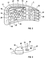
- FIG. 2 shows a section of a gas turbine blade 1, which largely corresponds to the embodiment from FIG. 1.
- a decisive improvement in cooling efficiency will, however by the arrangement of the projections 15 and the impingement cooling openings 19 scored.
- the projections 15 shield the impingement cooling jets 29, which emerge from the impingement cooling openings 19 opposite the cross flow 27. As a result, the impact cooling jets 29 not disturbed and hit almost ideally vertically to the cold side 16.
- a particularly efficient shielding is achieved by the special shape of the projections 15, what is explained in more detail with reference to Figure 3.
- FIG 3 shows in detail a part of the cooling structure of the gas turbine blade 1 from Figure 2.
- the projections 15 are with an oval contour so that on the one hand the cross flow 27 by one in the cross flow direction behind each Projection 15 lying baffle cooling opening 19 is passed around.
- the oval shape also leads to a low flow resistance for the cross flow 27.
- each projection 15 a bulge 43 on its based on the Cross flow direction on the downstream side. Through this Bulge 43 becomes a slipstream area particularly effectively 45 generated, which the influence of the cross flow 27 on the Impingement cooling jets 29 reduced particularly efficiently.
- the related on the upstream side 41 the projection 15 is still comparatively due to the oval contour large area, so that an improved Heat transfer from the origin 15 to the cooling air 25 results.
Abstract
Description
Die Erfindung betrifft ein Bauteil mit einer heißgas-beaufschlagbaren Wand, die eine Heißgasseite und eine der Heißgasseite gegenüberliegende Kaltseite aufweist, wobei die Wand einerseits durch entlang der Kaltseite als Querströmung in einer Querströmungsrichtung strömendes Kühlfluid und gleichzeitig durch senkrecht auf die Kaltseite als Prallkühlstrahlen aufprallendes Kühlfluid kühlbar ist.The invention relates to a component with a hot gas Wall that has a hot gas side and one of the Has hot gas side opposite cold side, the Wall on the one hand through along the cold side as a cross flow cooling fluid flowing in a cross flow direction and simultaneously by perpendicular to the cold side as impact cooling jets impacting cooling fluid is coolable.
Die US 5,328,331 offenbart eine kühlbare Gasturbinenschaufel. Die Gasturbinenschaufel weist eine integral gebildete Doppelwandstruktur in ihrem Schaufelblattbereich auf. Die Doppelwand ist von einer äußeren Schaufelblattwand und einer inneren Schaufelblattwand gebildet. Die äußere Schaufelblattwand und die innere Schaufelblattwand sind voneinander durch einen Schaufelwandhohlraum getrennt. Durch den Schaufelwandhohlraum führen die Schaufelaußenwand und die Schaufelinnenwand verbindend integral mit der Schaufelaußenwand und der Schaufelinnenwand ausgeführte Vorsprünge. Die Schaufelinnenwand ist mit Bohrungen durchsetzt. Die Schaufelinnenwand umschließt einen inneren Schaufelhohlraum, in den Kühlluft eingeleitet wird. Über die Bohrungen der Schaufelinnenwand tritt die Kühlluft in den Schaufelwandhohlraum ein, und zwar als senkrecht auf die Schaufelaußenwand gerichtete Prallkühlstrahlen. Hierdurch wird eine effektive Prallkühlung der Schaufelaußenwand erreicht.US 5,328,331 discloses a coolable gas turbine blade. The gas turbine blade has an integrally formed double wall structure in their airfoil area. The double wall is of an outer blade wall and an inner one Blade wall formed. The outer airfoil wall and the inner airfoil wall are separated from each other by one Bucket wall cavity separated. Through the vane wall cavity guide the blade outer wall and the blade inner wall connecting integral with the blade outer wall and the blade inner wall executed protrusions. The inner blade wall is interspersed with holes. Encloses the inner wall of the bucket an inner vane cavity into which cooling air is introduced becomes. This occurs over the holes in the inner wall of the blade Cooling air into the vane wall cavity as vertical Impact cooling jets directed at the outer wall of the blade. This results in effective impingement cooling of the outer wall of the blade reached.
Die WO 98/25009 offenbart eine Turbinenschaufel. Die Turbinenschaufel weist eine von einem Heißgas umströmbare Außenwand auf. Die Turbinenschaufel weist weiterhin eine Innenwand auf, so dass zwischen der Außenwand und der Innenwand ein Kühlbereich zur Durchströmung mit einem Kühlfluid gebildet ist. In den Kühlbereich sind entlang einer Hauptströmungsrichtung des Kühlfluides umströmbare Wärmeübertragungselemente hintereinander angeordnet, die wärmetechnisch mit der Außenwand verbunden sind. Durch eine Durchströmung des Kühlbereichs mit Kühlfluid wird eine konvektive Kühlung der Außenwand erreicht, die durch einen Wärmefluss von den Wärmeübertragungselementen auf das Kühlfluid verstärkt wird.WO 98/25009 discloses a turbine blade. The turbine blade has an outer wall around which a hot gas can flow on. The turbine blade also has an inner wall on so that between the outer wall and the inner wall Cooling area formed for the flow of a cooling fluid is. In the cooling area are along a main flow direction of the cooling fluid flow around heat transfer elements arranged one behind the other, the thermally with the External wall are connected. Through a flow through the cooling area with cooling fluid, convective cooling of the External wall reached by heat flow from the heat transfer elements is amplified on the cooling fluid.
Eine Leitschaufel einer Gasturbine mit einer Führung von Kühlgas zu deren Kühlung ist in der US 5,419 039 A beschrieben. Die Leitschaufel ist als ein Gussstück ausgeführt bzw. aus zwei Gussstücken zusammengesetzt. Sie weist in ihrem Inneren eine Zuführung von Kühlluft aus dem Verdichter der zugeordneten Gasturbinenanlage auf. In ihrer der Heißgasströmung der Gasturbine ausgesetzten, die Luftzuführung umschließenden Wandstruktur sind eingegossene einseitig offene Kühltaschen vorgesehen. Die Kühltaschen sind an der Außenseite der Wandstruktur sowohl in Strömungsrichtung des Heißgases als auch senkrecht zur Strömungsrichtung des Heißgases entlang der Hauptausdehnungsrichtung der Leitschaufel angeordnet. In jede Kühltasche strömt von der Kühlluftzuführung über eine Mehrzahl von Löchern in der Wandstruktur Kühlluft in die Kühltasche ein. Diese wird in Strömungsrichtung des Heißgases von der Kühlluft durchströmt und tritt in einem bereits durch das Gießen der Leitschaufeln gebildeten, sich über die gesamte Breite der Kühltasche erstreckenden Spalt in die Strömung des Heißgases aus.A gas turbine vane with a guide from Cooling gas for cooling it is described in US Pat. No. 5,419,039. The guide vane is designed as a casting or composed of two castings. She points inside a supply of cooling air from the compressor to the assigned Gas turbine plant on. In their the hot gas flow exposed to the gas turbine, enclosing the air supply Wall structures are cast-in open on one side Cooling bags provided. The cooler bags are on the outside the wall structure both in the flow direction of the hot gas as well as perpendicular to the direction of flow of the hot gas arranged along the main direction of expansion of the guide vane. The cooling air supply flows into each cooler bag cooling air through a plurality of holes in the wall structure in the cooler bag. This is in the flow direction of the Hot gas flows through the cooling air and already occurs in one formed by casting the guide vanes gap across the entire width of the cooler bag the flow of hot gas.
Aufgabe der Erfindung ist die Angabe eines Bauteils mit einer heißgas-beaufschlagbaren Wand, welches besonders effizient kühlbar ist.The object of the invention is to provide a component with a hot gas-exposed wall, which is particularly efficient is coolable.
Erfindungsgemäß wird diese Aufgabe gelöst durch Angabe eines Bauteils mit einer heißgas-beaufschlagbaren Wand, die eine Heißgasseite und eine der Heißgasseite gegenüberliegende Kaltseite aufweist, wobei die Wand einerseits durch entlang der Kaltseite als Querströmung in einer Querströmungsrichtung strömendes Kühlfluid und gleichzeitig durch senkrecht auf die Kaltseite als Prallkühlstrahlen aufprallendes Kühlfluid kühlbar ist, wobei die Prallkühlstrahlen gegenüber der Querströmung jeweils durch einen auf der Kaltseite angeordneten Vorsprung abgeschirmt sind.According to the invention, this object is achieved by specifying a Component with a hot gas-pressurized wall, the one Hot gas side and one opposite the hot gas side Cold side, the wall on the one hand along the cold side as a cross flow in a cross flow direction flowing cooling fluid and at the same time by perpendicular to the Cooling fluid that can be cooled as impact cooling jets, can be cooled is, the impingement cooling jets against the cross flow each by a projection arranged on the cold side are shielded.
Die Erfindung geht von der Erkenntnis aus, dass eine Kühlung der heißgasbeaufschlagbaren Wand sowohl durch eine Konvektionskühlung mittels eines entlang der Kaltseite strömenden Kühlfluides als auch mittels senkrecht auf die Kaltseite auftreffender Prallkühlstrahlen zwar zwei sehr effektive Kühlmechanismen miteinander verbindet, dies aber in gewöhnlicher Technologie zu einer Verringerung der Effizienz der Prallkühlung führt. Um die kühlende Querströmung einerseits beizubehalten, andererseits aber die Prallkühlung nicht zu beeinträchtigen, wird nun erstmals vorgeschlagen, die Prallkühlstrahlen mittels eines auf der Kaltseite angeordneten Vorsprungs so gegenüber der Querströmung abzuschirmen, dass eine Störung des senkrechten Auftreffens der Prallkühlstrahlen auf die Kaltseite durch die Querströmung zumindest weitgehend reduziert wird. Der Vorsprung kann dabei gleichzeitig als ein Wärmeübertragungselement dienen, welches die effektive Oberfläche der Kaltseite vergrößert und damit eine verstärkte Kühlung durch die Querströmung bewirkt. Somit werden erstmals die konvektive Kühlung mittels der Querströmung und die Prallkühlung mittels Prallkühlstrahlen so miteinander kombiniert, dass keine gegenseitige Beeinträchtigung erfolgt.The invention is based on the finding that cooling the hot gas wall, both by convection cooling by means of a flowing along the cold side Cooling fluids as well as by means of vertically hitting the cold side Impingement cooling jets are two very effective cooling mechanisms connects with each other, but in the usual Technology to reduce the efficiency of impingement cooling leads. To maintain the cooling cross-flow on the one hand, on the other hand not to affect the impingement cooling, is now proposed for the first time, the impact cooling jets by means of a projection arranged on the cold side shield against the cross flow so that a Interference with the vertical impingement of the impingement cooling jets the cold side is at least largely reduced by the cross flow becomes. The lead can also be considered a Heat transfer element serve which the effective surface the cold side enlarged and thus a reinforced Cooling caused by the cross flow. Thus, for the first time the convective cooling by means of the cross flow and the Impingement cooling combined with impingement cooling jets that there is no mutual interference.
Vorzugsweise weisen zumindest einige der Vorsprünge auf ihrer bezüglich der Querströmungsrichtung abströmseitigen Seite eine Ausbuchtung auf, die in der Querströmung ein Windschattengebiet erzeugt, in welchem Windschattengebiet ein Prallkühlstrahl auf die Kaltseite auftrifft. Der Vorsprung ist also durch die Ausbuchtung gezielt so gestaltet, dass ein ausgeprägtes Windschattengebiet auf der abströmseitigen Seite des Vorsprungs entsteht. In diesem Windschattengebiet kann der Prallkühlstrahl nahezu unbeeinträchtigt von der Querströmung senkrecht auf die Kaltseite auftreffen und hierdurch eine effektive Prallkühlung bewirken. Preferably at least some of the protrusions have on them with respect to the cross flow direction downstream side a bulge on that in the cross flow a slipstream area generates in which slipstream area an impact cooling jet strikes the cold side. The lead is specifically designed by the bulge so that a pronounced slipstream area on the downstream side of the lead. In this slipstream area the impact cooling jet is almost unaffected by the cross flow hit vertically on the cold side and thereby effective baffle cooling.
Bevorzugt weisen zumindest einige der Vorsprünge auf ihrer bezüglich der Querströmungsrichtung anströmigen Seite eine Kontur mit einem niedrigen Strömungswiderstand für die Querströmung auf. Eine solche Kontur kann z.B. eine etwa ovale Form sein, wobei eine Spitze des Ovals entgegen der Querströmungsrichtung gerichtet ist. Durch den niedrigen Strömungswiderstand für die Querströmung wird diese in ihrer Strömungsgeschwindigkeit nur geringfügig durch die Vorsprünge beeinträchtigt, was wiederum eine hohe konvektive Kühlung für die Kaltseite zur Folge hat. Zudem ergibt sich bei einer Kontur mit einem niedrigen Strömungswiderstand eine vergleichsweise große Oberfläche des Vorsprungs. Hierdurch wird ein Wärmeübertrag von der Wand auf das Kühlfluid weiter verstärkt.Preferably, at least some of the projections have on them with respect to the cross-flow direction side one Contour with a low flow resistance for the cross flow on. Such a contour can e.g. an approximately oval Be shape with a tip of the oval opposite the cross flow direction is directed. Due to the low flow resistance for the cross flow this is in its flow velocity only slightly affected by the protrusions, which in turn provides high convective cooling for the Cold side. In addition, there is a contour a comparatively low flow resistance large surface of the tab. This is a heat transfer further reinforced from the wall to the cooling fluid.
Vorzugsweise ist beabstandet von der Kaltseite eine Prallkühlwand angeordnet, die zumindest über einige der Vorsprünge mit der Wand verbunden ist. In der Prallkühlwand sind Öffnungen vorgesehen, aus denen die Prallkühlstrahlen austreten. Die Verbindung der Prallkühlwand über die Vorsprünge mit der Wand ermöglicht einerseits eine einfache Befestigung der Prallkühlwand und andererseits eine weiter verbesserte Wärmeübertragung durch Wärmeleitung aus den Vorsprüngen heraus in die Prallkühlwand.A baffle cooling wall is preferably spaced from the cold side arranged at least over some of the protrusions is connected to the wall. There are openings in the baffle cooling wall provided, from which the impact cooling jets emerge. The connection of the baffle cooling wall via the projections with the On the one hand, wall allows easy attachment of the Baffle cooling wall and on the other hand a further improved heat transfer by conduction from the protrusions the baffle cooling wall.
Vorzugsweise ist das Bauteil als Gasturbinenschaufel ausgeführt, wobei die Wand eine Schaufelblattaußenwand ist. Eine Gasturbinenschaufel ist besonders hohen thermischen Belastungen ausgesetzt, die in der Regel nur durch eine effektive Kühlung aufgefangen werden können. Jede Verbesserung in der Kühleffizienz bei einer Gasturbinenschaufel führt zu einem niedrigeren Kühlluftverbrauch und dies führt wiederum zu einem verbesserten Wirkungsgrad einer Gasturbine, in der die Gasturbinenschaufel eingebaut ist.The component is preferably designed as a gas turbine blade, the wall being an outer blade wall. A Gas turbine blade is particularly high thermal loads exposed, usually only through effective Cooling can be caught. Any improvement in the Cooling efficiency in a gas turbine blade leads to one lower cooling air consumption and this in turn leads to a improved efficiency of a gas turbine in which the Gas turbine blade is installed.
Bevorzugt ist die Prallkühlwand eine Schaufelblattinnenwand. Die Schaufelblattinnenwand kann sowohl integral mit der Schaufelblattaußenwand geformt sein, als auch als ein Prallkühleinsatz im Schaufelblatt-Inneren ausgeführt sein. Einer so ausgestalteten Gasturbinenschaufel wird Kühlluft ins Schaufelblatt-Innere zugeführt. Über die Schaufelblatt-Innenwand tritt diese Kühlluft über Prallkühlöffnungen als-Prallkühlstrahlen aus und trifft auf die Kaltseite der Schaufelblatt-Außenwand.The baffle cooling wall is preferably an airfoil inner wall. The airfoil inner wall can be both integral with the Blade outer wall can be shaped as well as an impact cooling insert be carried out in the interior of the airfoil. one thus designed gas turbine blade is cooling air into Airfoil interior fed. Over the airfoil inner wall this cooling air passes over impingement cooling openings as impinging cooling jets and hits the cold side of the outer blade wall.
Bevorzugtermaßen ist das Kühlfluid Kühlluft.The cooling fluid is preferably cooling air.
Weiter bevorzugt ist die Wand mit den Vorsprüngen einstückig gegossen.The wall with the projections is further preferably in one piece cast.
Vorzugsweise ist das Bauteil als Gasturbinenleitschaufel ausgeführt.The component is preferably designed as a gas turbine guide vane.
Die Erfindung wird anhand der Zeichnung beispielhaft näher erläutert. Es zeigen teilweise schematisch und nicht maßstäblich:
- FIG 1
- eine Gasturbinenschaufel nach dem Stand der Technik,
- FIG 2
- einen Ausschnitt einer Gasturbinenschaufel mit verbesserter Kühlung, und
- FIG 3
- eine Detailansicht der Kühlstruktur aus Figur 2.
- FIG. 1
- a gas turbine blade according to the prior art,
- FIG 2
- a section of a gas turbine blade with improved cooling, and
- FIG 3
- a detailed view of the cooling structure of Figure 2.
Gleiche Bezugszeichen haben in den verschiedenen Figuren die gleiche Bedeutung.The same reference numerals have in the different figures same meaning.
Figur 1 zeigt eine Gasturbinenschaufel 1. Die Gasturbinenschaufel
1 weist einen Schaufelblattbereich 3, einen Plattformbereich
5 und einen Befestigungsbereich 7 auf. Der Schaufelblattbereich
3 weist eine Schaufelblattaußenwand 9 auf.
Die Schaufelblattaußenwand 9 umschließt einen inneren Hohlraum
11. In dem inneren Hohlraum 11 ist gleich verlaufend zur
Schaufelblattaußenwand 9 eine Schaufelblattinnenwand 13 so
angeordnet, dass zwischen der Schaufelblattaußenwand 9 und
der Schaufelblattinnenwand 13 ein Wandhohlraum 14 gebildet
ist. Die Schaufelblattinnenwand 11 ist mit der Schaufelblattaußenwand
9 über zylindrisch ausgeführte Vorsprünge 15 verbunden,
die an der innenliegenden Kaltseite 16 der Schaufelaußenwand
9 angeordnet sind. Der Kaltseite 16 gegenüberliegend
weist die Schaufelaußenwand 9 eine Heißgasseite 18 auf,
die im Betrieb einer Gasturbine, in die die Gasturbinenschaufel
1 eingebaut ist, die Schaufelaußenwand 9 umströmt. Bei
einer solchen Umströmung mit Heißgas wird die Gasturbinenschaufel
1 so hohen Temperaturen ausgesetzt, dass eine Kühlung
mittels Kühlluft 25 nötig ist, die in einen von der
Schaufelblattinnenwand 13 umschlossenen Schaufelhohlraum 17
eingeleitet wird. Vom Schaufelhohlraum 17 tritt die Kühlluft
25 über Bohrungen 19 in der Schaufelblattinnenwand 13 in den
Wandhohlraum 14 in Form von Prallkühlstrahlen 29 aus. Die
Prallkühlstrahlen 29 treffen auf die Kaltseite 16 der Schaufelblattaußenwand
9. Die aufgeprallte Kühlluft 25 bildet sodann
eine Querströmung 27 in Richtung auf eine Schaufelblatthinterkante
23. Im Bereich der Schaufelblatthinterkante 23
tritt die Kühlluft 25 über Kanäle 21 aus. Die Vielzahl von
Prallkühlstrahlen 29 führt zu einer sich immer weiter in
Richtung auf die Schaufelhinterkante 23 verstärkenden Querströmung
27. Diese Querströmung 27 stört die Prallkühlstrahlen
29, da diese nicht mehr ideal senkrecht auf die Kaltseite
16 auftreffen. Die Effektivität der Prallkühlung wird somit
durch die Querströmung 27 verringert. Dieser Nachteil wird
durch ein neues Kühlkonzept vermieden, welches näher anhand
der Figuren 2 und 3 erläutert wird.Figure 1 shows a
Figur 2 zeigt einen Ausschnitt einer Gasturbinenschaufel 1,
der in weiten Teilen der Ausführung aus Figur 1 entspricht.
Eine entscheidende Verbesserung der Kühleffizienz wird aber
durch die Anordnung der Vorsprünge 15 und der Prallkühlöffnungen
19 erzielt. Die Vorsprünge 15 schirmen die Prallkühlstrahlen
29, die aus den Prallkühlöffnungen 19 austreten, gegenüber
der Querströmung 27 ab. Hierdurch werden die Prallkühlstrahlen
29 nicht gestört und treffen nahezu ideal senkrecht
auf die Kaltseite 16. Eine besonders effiziente Abschirmung
wird durch die besondere Form der Vorsprünge 15 erzielt,
was näher anhand von Figur 3 erläutert wird.FIG. 2 shows a section of a
Figur 3 zeigt im Detail einen Teil der Kühlstruktur der Gasturbinenschaufel
1 aus Figur 2. Die Vorsprünge 15 sind mit
einer ovalen Kontur so ausgebildet, dass einerseits die Querströmung
27 um eine in Querströmungsrichtung hinter jedem
Vorsprung 15 liegende Prallkühlöffnung 19 herumgeleitet wird.
Die ovale Form führt zudem zu einem niedrigen Strömungswiderstand
für die Querströmung 27. Weiterhin weist jeder Vorsprung
15 eine Ausbuchtung 43 auf seiner bezogen auf die
Querströmungsrichtung abströmseitigen Seite auf. Durch diese
Ausbuchtung 43 wird besonders effektiv ein Windschattengebiet
45 erzeugt, welches den Einfluß der Querströmung 27 auf die
Prallkühlstrahlen 29 besonders effizient verringert. Die bezogen
auf die Querströmungsrichtung anströmseitige Seite 41
des Vorsprungs 15 ist durch die ovale Kontur weiterhin vergleichsweise
großflächig ausgebildet, so dass sich ein verbesserter
Wärmeübertrag aus dem Ursprung 15 auf die Kühlluft
25 ergibt.Figure 3 shows in detail a part of the cooling structure of the
Claims (8)
Priority Applications (1)
| Application Number | Priority Date | Filing Date | Title |
|---|---|---|---|
| EP00120031A EP1188902A1 (en) | 2000-09-14 | 2000-09-14 | Impingement cooled wall |
Applications Claiming Priority (1)
| Application Number | Priority Date | Filing Date | Title |
|---|---|---|---|
| EP00120031A EP1188902A1 (en) | 2000-09-14 | 2000-09-14 | Impingement cooled wall |
Publications (1)
| Publication Number | Publication Date |
|---|---|
| EP1188902A1 true EP1188902A1 (en) | 2002-03-20 |
Family
ID=8169833
Family Applications (1)
| Application Number | Title | Priority Date | Filing Date |
|---|---|---|---|
| EP00120031A Withdrawn EP1188902A1 (en) | 2000-09-14 | 2000-09-14 | Impingement cooled wall |
Country Status (1)
| Country | Link |
|---|---|
| EP (1) | EP1188902A1 (en) |
Cited By (24)
| Publication number | Priority date | Publication date | Assignee | Title |
|---|---|---|---|---|
| EP1574669A2 (en) * | 2004-03-10 | 2005-09-14 | Rolls-Royce Plc | Impingement cooling arrangement witin turbine blades |
| EP1544412A3 (en) * | 2003-12-19 | 2008-11-26 | United Technologies Corporation | Cooled rotor blade with vibration damping device |
| EP2031244A1 (en) * | 2007-08-31 | 2009-03-04 | Lm Glasfiber A/S | Means to maintain flow of a flowing medium attached to the exterior of a flow control member by use of crossing sub-channels |
| EP2159376A2 (en) | 2008-08-28 | 2010-03-03 | United Technologies Corporation | Airfoil insert and method for cooling an airfoil |
| EP2233694A1 (en) * | 2009-03-26 | 2010-09-29 | United Technologies Corporation | Metering standoffs for airfoil baffle |
| WO2011020485A1 (en) * | 2009-08-20 | 2011-02-24 | Siemens Aktiengesellschaft | Cross-flow blockers in a gas turbine impingement cooling gap |
| EP2412925A1 (en) * | 2009-03-26 | 2012-02-01 | Mitsubishi Heavy Industries, Ltd. | Turbine blade and gas turbine |
| CN102839991A (en) * | 2011-06-20 | 2012-12-26 | 通用电气公司 | Hot gas path component |
| CN103975129A (en) * | 2011-12-15 | 2014-08-06 | 株式会社Ihi | Impingement cooling mechanism, turbine blade and combustor |
| CN103994468A (en) * | 2013-02-20 | 2014-08-20 | 株式会社日立制作所 | Gas turbine combustor equipped with heat-transfer device |
| WO2014150681A1 (en) * | 2013-03-15 | 2014-09-25 | United Technologies Corporation | Gas turbine engine component having shaped pedestals |
| EP1760265B1 (en) | 2005-08-31 | 2015-07-15 | United Technologies Corporation | Turbine engine component with a cooling microcircuit and corresponding manufacturing method |
| EP2902589A1 (en) * | 2014-01-29 | 2015-08-05 | Siemens Aktiengesellschaft | Impact cooled component for a gas turbine |
| WO2015157780A1 (en) * | 2014-04-09 | 2015-10-15 | Siemens Aktiengesellschaft | Internal cooling system with insert forming nearwall cooling channels in an aft cooling cavity of a gas turbine airfoil including heat dissipating ribs |
| EP2955443A1 (en) * | 2014-06-11 | 2015-12-16 | Alstom Technology Ltd | Impingement cooled wall arrangement |
| WO2016036366A1 (en) * | 2014-09-04 | 2016-03-10 | Siemens Aktiengesellschaft | Internal cooling system with insert forming nearwall cooling channels in an aft cooling cavity of a gas turbine airfoil |
| WO2016036367A1 (en) * | 2014-09-04 | 2016-03-10 | Siemens Aktiengesellschaft | Internal cooling system with insert forming nearwall cooling channels in midchord cooling cavities of a gas turbine airfoil |
| US20170067365A1 (en) * | 2015-09-09 | 2017-03-09 | General Electric Company | Exhaust frame strut with cooling fins |
| EP2610436A3 (en) * | 2011-12-30 | 2017-06-21 | General Electric Company | Turbine rotor blade platform cooling |
| US9863255B2 (en) | 2012-02-15 | 2018-01-09 | Siemens Aktiengesellschaft | Impingement cooling of turbine blades or vanes |
| CN108119238A (en) * | 2016-11-30 | 2018-06-05 | 通用电气公司 | The impingement insert of gas-turbine unit |
| US20180163545A1 (en) * | 2016-12-08 | 2018-06-14 | Doosan Heavy Industries & Construction Co., Ltd | Cooling structure for vane |
| US20180328224A1 (en) * | 2017-05-09 | 2018-11-15 | General Electric Company | Impingement insert |
| CN110700893A (en) * | 2019-10-14 | 2020-01-17 | 哈尔滨工程大学 | Gas turbine blade comprising V-rib-pit composite cooling structure |
Citations (4)
| Publication number | Priority date | Publication date | Assignee | Title |
|---|---|---|---|---|
| DE2657405A1 (en) * | 1975-12-20 | 1977-07-07 | Rolls Royce 1971 Ltd | SURFACE COOLING DEVICE, IN PARTICULAR FOR GAS TURBINE ENGINES |
| US5328331A (en) | 1993-06-28 | 1994-07-12 | General Electric Company | Turbine airfoil with double shell outer wall |
| US5419039A (en) | 1990-07-09 | 1995-05-30 | United Technologies Corporation | Method of making an air cooled vane with film cooling pocket construction |
| WO1998025009A1 (en) | 1996-12-02 | 1998-06-11 | Siemens Aktiengesellschaft | Turbine blade and its use in a gas turbine system |
-
2000
- 2000-09-14 EP EP00120031A patent/EP1188902A1/en not_active Withdrawn
Patent Citations (4)
| Publication number | Priority date | Publication date | Assignee | Title |
|---|---|---|---|---|
| DE2657405A1 (en) * | 1975-12-20 | 1977-07-07 | Rolls Royce 1971 Ltd | SURFACE COOLING DEVICE, IN PARTICULAR FOR GAS TURBINE ENGINES |
| US5419039A (en) | 1990-07-09 | 1995-05-30 | United Technologies Corporation | Method of making an air cooled vane with film cooling pocket construction |
| US5328331A (en) | 1993-06-28 | 1994-07-12 | General Electric Company | Turbine airfoil with double shell outer wall |
| WO1998025009A1 (en) | 1996-12-02 | 1998-06-11 | Siemens Aktiengesellschaft | Turbine blade and its use in a gas turbine system |
Cited By (53)
| Publication number | Priority date | Publication date | Assignee | Title |
|---|---|---|---|---|
| EP1544412A3 (en) * | 2003-12-19 | 2008-11-26 | United Technologies Corporation | Cooled rotor blade with vibration damping device |
| EP1574669A2 (en) * | 2004-03-10 | 2005-09-14 | Rolls-Royce Plc | Impingement cooling arrangement witin turbine blades |
| EP1574669A3 (en) * | 2004-03-10 | 2012-07-18 | Rolls-Royce Plc | Impingement cooling arrangement witin turbine blades |
| EP1760265B1 (en) | 2005-08-31 | 2015-07-15 | United Technologies Corporation | Turbine engine component with a cooling microcircuit and corresponding manufacturing method |
| EP2031244A1 (en) * | 2007-08-31 | 2009-03-04 | Lm Glasfiber A/S | Means to maintain flow of a flowing medium attached to the exterior of a flow control member by use of crossing sub-channels |
| US8550787B2 (en) | 2007-08-31 | 2013-10-08 | Lm Glasfiber A/S | Wind turbine blade with submerged boundary layer control means comprising crossing sub-channels |
| EP2159376A3 (en) * | 2008-08-28 | 2012-03-21 | United Technologies Corporation | Airfoil insert and method for cooling an airfoil |
| EP2159376A2 (en) | 2008-08-28 | 2010-03-03 | United Technologies Corporation | Airfoil insert and method for cooling an airfoil |
| EP2233695A1 (en) | 2009-03-26 | 2010-09-29 | United Technologies Corporation | Recessed standoffs for airfoil baffle |
| EP2233694A1 (en) * | 2009-03-26 | 2010-09-29 | United Technologies Corporation | Metering standoffs for airfoil baffle |
| EP2412925A1 (en) * | 2009-03-26 | 2012-02-01 | Mitsubishi Heavy Industries, Ltd. | Turbine blade and gas turbine |
| US8109724B2 (en) | 2009-03-26 | 2012-02-07 | United Technologies Corporation | Recessed metering standoffs for airfoil baffle |
| EP2412925A4 (en) * | 2009-03-26 | 2013-05-08 | Mitsubishi Heavy Ind Ltd | Turbine blade and gas turbine |
| US8480366B2 (en) | 2009-03-26 | 2013-07-09 | United Technologies Corporation | Recessed metering standoffs for airfoil baffle |
| WO2011020485A1 (en) * | 2009-08-20 | 2011-02-24 | Siemens Aktiengesellschaft | Cross-flow blockers in a gas turbine impingement cooling gap |
| CN102839991A (en) * | 2011-06-20 | 2012-12-26 | 通用电气公司 | Hot gas path component |
| EP2538025B1 (en) * | 2011-06-20 | 2018-08-08 | General Electric Company | Hot gas path component and corresponding method of forming a component |
| CN102839991B (en) * | 2011-06-20 | 2015-08-19 | 通用电气公司 | Hot gas path component |
| CN103975129A (en) * | 2011-12-15 | 2014-08-06 | 株式会社Ihi | Impingement cooling mechanism, turbine blade and combustor |
| US9771809B2 (en) | 2011-12-15 | 2017-09-26 | Ihi Corporation | Impingement cooling mechanism, turbine blade and combustor |
| CN103975129B (en) * | 2011-12-15 | 2016-06-29 | 株式会社Ihi | Impinging cooling mechanism, the turbine wing and burner |
| EP2610436A3 (en) * | 2011-12-30 | 2017-06-21 | General Electric Company | Turbine rotor blade platform cooling |
| US9863255B2 (en) | 2012-02-15 | 2018-01-09 | Siemens Aktiengesellschaft | Impingement cooling of turbine blades or vanes |
| CN103994468A (en) * | 2013-02-20 | 2014-08-20 | 株式会社日立制作所 | Gas turbine combustor equipped with heat-transfer device |
| US9435536B2 (en) | 2013-02-20 | 2016-09-06 | Mitsubishi Hitachi Power Systems, Ltd. | Gas turbine combustor equipped with heat-transfer device |
| CN103994468B (en) * | 2013-02-20 | 2017-01-04 | 三菱日立电力系统株式会社 | Possesses the gas turbine burner of heat transfer unit (HTU) |
| EP2770258A3 (en) * | 2013-02-20 | 2015-07-15 | Mitsubishi Hitachi Power Systems, Ltd. | Gas turbine combustor equipped with heat-transfer device |
| US10358978B2 (en) | 2013-03-15 | 2019-07-23 | United Technologies Corporation | Gas turbine engine component having shaped pedestals |
| WO2014150681A1 (en) * | 2013-03-15 | 2014-09-25 | United Technologies Corporation | Gas turbine engine component having shaped pedestals |
| EP2902589A1 (en) * | 2014-01-29 | 2015-08-05 | Siemens Aktiengesellschaft | Impact cooled component for a gas turbine |
| WO2015157780A1 (en) * | 2014-04-09 | 2015-10-15 | Siemens Aktiengesellschaft | Internal cooling system with insert forming nearwall cooling channels in an aft cooling cavity of a gas turbine airfoil including heat dissipating ribs |
| EP2955442A1 (en) * | 2014-06-11 | 2015-12-16 | Alstom Technology Ltd | Impingement cooled wall arrangement |
| EP2955443A1 (en) * | 2014-06-11 | 2015-12-16 | Alstom Technology Ltd | Impingement cooled wall arrangement |
| RU2696830C2 (en) * | 2014-06-11 | 2019-08-06 | Ансалдо Энерджиа Свитзерлэнд Аг | Device for wall cooling injection |
| US10060352B2 (en) | 2014-06-11 | 2018-08-28 | Ansaldo Energia Switzerland AG | Impingement cooled wall arrangement |
| WO2016036366A1 (en) * | 2014-09-04 | 2016-03-10 | Siemens Aktiengesellschaft | Internal cooling system with insert forming nearwall cooling channels in an aft cooling cavity of a gas turbine airfoil |
| CN106795771B (en) * | 2014-09-04 | 2018-11-30 | 西门子公司 | Inner cooling system with the insertion piece for forming nearly wall cooling duct in cooling chamber in the middle part of the wing chord of gas turbine aerofoil profile |
| CN107075955A (en) * | 2014-09-04 | 2017-08-18 | 西门子公司 | Include the inner cooling system of cooling fin with the insert that nearly wall cooling duct is formed in the rear portion cooling chamber of combustion gas turbine airfoil |
| US9863256B2 (en) | 2014-09-04 | 2018-01-09 | Siemens Aktiengesellschaft | Internal cooling system with insert forming nearwall cooling channels in an aft cooling cavity of an airfoil usable in a gas turbine engine |
| WO2016036367A1 (en) * | 2014-09-04 | 2016-03-10 | Siemens Aktiengesellschaft | Internal cooling system with insert forming nearwall cooling channels in midchord cooling cavities of a gas turbine airfoil |
| US9840930B2 (en) | 2014-09-04 | 2017-12-12 | Siemens Aktiengesellschaft | Internal cooling system with insert forming nearwall cooling channels in midchord cooling cavities of a gas turbine airfoil |
| CN106661945A (en) * | 2014-09-04 | 2017-05-10 | 西门子公司 | Internal Cooling System With Insert Forming Nearwall Cooling Channels In An Aft Cooling Cavity Of A Gas Turbine Airfoil |
| CN106795771A (en) * | 2014-09-04 | 2017-05-31 | 西门子公司 | Inner cooling system with the insert that nearly wall cooling duct is formed in cooling chamber in the middle part of the wing chord of gas turbine aerofoil profile |
| US20170067365A1 (en) * | 2015-09-09 | 2017-03-09 | General Electric Company | Exhaust frame strut with cooling fins |
| EP3330486A1 (en) * | 2016-11-30 | 2018-06-06 | General Electric Company | Impingement insert for a gas turbine engine |
| CN108119238A (en) * | 2016-11-30 | 2018-06-05 | 通用电气公司 | The impingement insert of gas-turbine unit |
| US11519281B2 (en) | 2016-11-30 | 2022-12-06 | General Electric Company | Impingement insert for a gas turbine engine |
| CN108119238B (en) * | 2016-11-30 | 2022-10-14 | 通用电气公司 | Impingement insert for a gas turbine engine |
| US20180163545A1 (en) * | 2016-12-08 | 2018-06-14 | Doosan Heavy Industries & Construction Co., Ltd | Cooling structure for vane |
| US10968755B2 (en) * | 2016-12-08 | 2021-04-06 | DOOSAN Heavy Industries Construction Co., LTD | Cooling structure for vane |
| US20180328224A1 (en) * | 2017-05-09 | 2018-11-15 | General Electric Company | Impingement insert |
| US10494948B2 (en) * | 2017-05-09 | 2019-12-03 | General Electric Company | Impingement insert |
| CN110700893A (en) * | 2019-10-14 | 2020-01-17 | 哈尔滨工程大学 | Gas turbine blade comprising V-rib-pit composite cooling structure |
Similar Documents
| Publication | Publication Date | Title |
|---|---|---|
| EP1188902A1 (en) | Impingement cooled wall | |
| EP1320661B1 (en) | Gas turbine blade | |
| DE69822100T2 (en) | turbine blade | |
| DE69714960T3 (en) | Whirl element construction for cooling channels of a gas turbine rotor blade | |
| EP1112439B1 (en) | Turbine bucket | |
| EP0798448B1 (en) | System and device to cool a wall which is heated on one side by hot gas | |
| DE4441507C3 (en) | Cooled turbine blade | |
| DE1946535C3 (en) | Component for a gas turbine engine | |
| DE10001109B4 (en) | Cooled shovel for a gas turbine | |
| DE60015233T2 (en) | Turbine blade with internal cooling | |
| DE3248161C2 (en) | ||
| DE2703815C3 (en) | Cooled turbine blade | |
| DE2657405A1 (en) | SURFACE COOLING DEVICE, IN PARTICULAR FOR GAS TURBINE ENGINES | |
| DE102006004437A1 (en) | Blade of a gas turbine blade, method of making a blade, gasket plate and gas turbine | |
| DE2042947A1 (en) | Blade arrangement with cooling device | |
| DE102005044183A1 (en) | Apparatus and method for cooling turbine blade platforms | |
| DE102005019652A1 (en) | Turbulator on the underside of a turbine blade tip deflection bend and associated method | |
| EP1112440B1 (en) | Turbine guide blade | |
| EP0892149B1 (en) | Cooling system for the leading edge of a hollow blade for a gas turbine engine | |
| EP0825332A1 (en) | Coolable blade | |
| DE10344843A1 (en) | Integrated rotary knife edge injection arrangement | |
| WO2003054356A1 (en) | Thermally loaded component | |
| EP0954680B1 (en) | Turbine blade and its use in a gas turbine system | |
| DE102005024696A1 (en) | Component part of especially turbo-engine has protective shroud installed around sleeve element to protect section of sleeve element protruding from cooling passage against effects of surrounding flow | |
| EP0892150B1 (en) | System for cooling the trailing edge of a hollow gasturbine blade |
Legal Events
| Date | Code | Title | Description |
|---|---|---|---|
| PUAI | Public reference made under article 153(3) epc to a published international application that has entered the european phase |
Free format text: ORIGINAL CODE: 0009012 |
|
| AK | Designated contracting states |
Kind code of ref document: A1 Designated state(s): AT BE CH CY DE DK ES FI FR GB GR IE IT LI LU MC NL PT SE |
|
| AX | Request for extension of the european patent |
Free format text: AL;LT;LV;MK;RO;SI |
|
| AKX | Designation fees paid | ||
| REG | Reference to a national code |
Ref country code: DE Ref legal event code: 8566 |
|
| STAA | Information on the status of an ep patent application or granted ep patent |
Free format text: STATUS: THE APPLICATION IS DEEMED TO BE WITHDRAWN |
|
| 18D | Application deemed to be withdrawn |
Effective date: 20020921 |