EP1184566A1 - Aerogenerator blade - Google Patents
Aerogenerator blade Download PDFInfo
- Publication number
- EP1184566A1 EP1184566A1 EP00929568A EP00929568A EP1184566A1 EP 1184566 A1 EP1184566 A1 EP 1184566A1 EP 00929568 A EP00929568 A EP 00929568A EP 00929568 A EP00929568 A EP 00929568A EP 1184566 A1 EP1184566 A1 EP 1184566A1
- Authority
- EP
- European Patent Office
- Prior art keywords
- blade
- tube
- tracts
- ribs
- frames
- Prior art date
- Legal status (The legal status is an assumption and is not a legal conclusion. Google has not performed a legal analysis and makes no representation as to the accuracy of the status listed.)
- Withdrawn
Links
- OKTJSMMVPCPJKN-UHFFFAOYSA-N Carbon Chemical compound [C] OKTJSMMVPCPJKN-UHFFFAOYSA-N 0.000 claims description 11
- 229910052799 carbon Inorganic materials 0.000 claims description 11
- 239000000835 fiber Substances 0.000 claims description 11
- 239000000203 mixture Substances 0.000 claims description 11
- 239000003365 glass fiber Substances 0.000 claims description 10
- 229910000831 Steel Inorganic materials 0.000 claims description 3
- 230000005484 gravity Effects 0.000 claims description 3
- 239000010959 steel Substances 0.000 claims description 3
- 238000005452 bending Methods 0.000 claims description 2
- 230000005611 electricity Effects 0.000 claims description 2
- 230000003068 static effect Effects 0.000 claims description 2
- 230000002093 peripheral effect Effects 0.000 claims 1
- 238000004026 adhesive bonding Methods 0.000 abstract description 2
- 229920000049 Carbon (fiber) Polymers 0.000 abstract 3
- 239000004917 carbon fiber Substances 0.000 abstract 3
- VNWKTOKETHGBQD-UHFFFAOYSA-N methane Chemical compound C VNWKTOKETHGBQD-UHFFFAOYSA-N 0.000 abstract 3
- 239000011152 fibreglass Chemical class 0.000 abstract 2
- 238000010276 construction Methods 0.000 description 5
- 239000000463 material Substances 0.000 description 5
- 239000002184 metal Substances 0.000 description 4
- 230000003750 conditioning effect Effects 0.000 description 2
- 238000010408 sweeping Methods 0.000 description 2
- 230000004888 barrier function Effects 0.000 description 1
- 230000000694 effects Effects 0.000 description 1
- 238000010348 incorporation Methods 0.000 description 1
- 230000005476 size effect Effects 0.000 description 1
Images


Classifications
-
- F—MECHANICAL ENGINEERING; LIGHTING; HEATING; WEAPONS; BLASTING
- F03—MACHINES OR ENGINES FOR LIQUIDS; WIND, SPRING, OR WEIGHT MOTORS; PRODUCING MECHANICAL POWER OR A REACTIVE PROPULSIVE THRUST, NOT OTHERWISE PROVIDED FOR
- F03D—WIND MOTORS
- F03D1/00—Wind motors with rotation axis substantially parallel to the air flow entering the rotor
- F03D1/06—Rotors
- F03D1/065—Rotors characterised by their construction elements
-
- F—MECHANICAL ENGINEERING; LIGHTING; HEATING; WEAPONS; BLASTING
- F03—MACHINES OR ENGINES FOR LIQUIDS; WIND, SPRING, OR WEIGHT MOTORS; PRODUCING MECHANICAL POWER OR A REACTIVE PROPULSIVE THRUST, NOT OTHERWISE PROVIDED FOR
- F03D—WIND MOTORS
- F03D80/00—Details, components or accessories not provided for in groups F03D1/00 - F03D17/00
- F03D80/30—Lightning protection
-
- F—MECHANICAL ENGINEERING; LIGHTING; HEATING; WEAPONS; BLASTING
- F05—INDEXING SCHEMES RELATING TO ENGINES OR PUMPS IN VARIOUS SUBCLASSES OF CLASSES F01-F04
- F05B—INDEXING SCHEME RELATING TO WIND, SPRING, WEIGHT, INERTIA OR LIKE MOTORS, TO MACHINES OR ENGINES FOR LIQUIDS COVERED BY SUBCLASSES F03B, F03D AND F03G
- F05B2230/00—Manufacture
- F05B2230/20—Manufacture essentially without removing material
- F05B2230/23—Manufacture essentially without removing material by permanently joining parts together
-
- F—MECHANICAL ENGINEERING; LIGHTING; HEATING; WEAPONS; BLASTING
- F05—INDEXING SCHEMES RELATING TO ENGINES OR PUMPS IN VARIOUS SUBCLASSES OF CLASSES F01-F04
- F05B—INDEXING SCHEME RELATING TO WIND, SPRING, WEIGHT, INERTIA OR LIKE MOTORS, TO MACHINES OR ENGINES FOR LIQUIDS COVERED BY SUBCLASSES F03B, F03D AND F03G
- F05B2240/00—Components
- F05B2240/20—Rotors
- F05B2240/30—Characteristics of rotor blades, i.e. of any element transforming dynamic fluid energy to or from rotational energy and being attached to a rotor
- F05B2240/302—Segmented or sectional blades
-
- F—MECHANICAL ENGINEERING; LIGHTING; HEATING; WEAPONS; BLASTING
- F05—INDEXING SCHEMES RELATING TO ENGINES OR PUMPS IN VARIOUS SUBCLASSES OF CLASSES F01-F04
- F05B—INDEXING SCHEME RELATING TO WIND, SPRING, WEIGHT, INERTIA OR LIKE MOTORS, TO MACHINES OR ENGINES FOR LIQUIDS COVERED BY SUBCLASSES F03B, F03D AND F03G
- F05B2280/00—Materials; Properties thereof
- F05B2280/20—Inorganic materials, e.g. non-metallic materials
- F05B2280/2006—Carbon, e.g. graphite
-
- F—MECHANICAL ENGINEERING; LIGHTING; HEATING; WEAPONS; BLASTING
- F05—INDEXING SCHEMES RELATING TO ENGINES OR PUMPS IN VARIOUS SUBCLASSES OF CLASSES F01-F04
- F05B—INDEXING SCHEME RELATING TO WIND, SPRING, WEIGHT, INERTIA OR LIKE MOTORS, TO MACHINES OR ENGINES FOR LIQUIDS COVERED BY SUBCLASSES F03B, F03D AND F03G
- F05B2280/00—Materials; Properties thereof
- F05B2280/60—Properties or characteristics given to material by treatment or manufacturing
- F05B2280/6003—Composites; e.g. fibre-reinforced
-
- F—MECHANICAL ENGINEERING; LIGHTING; HEATING; WEAPONS; BLASTING
- F05—INDEXING SCHEMES RELATING TO ENGINES OR PUMPS IN VARIOUS SUBCLASSES OF CLASSES F01-F04
- F05B—INDEXING SCHEME RELATING TO WIND, SPRING, WEIGHT, INERTIA OR LIKE MOTORS, TO MACHINES OR ENGINES FOR LIQUIDS COVERED BY SUBCLASSES F03B, F03D AND F03G
- F05B2280/00—Materials; Properties thereof
- F05B2280/60—Properties or characteristics given to material by treatment or manufacturing
- F05B2280/6013—Fibres
-
- F—MECHANICAL ENGINEERING; LIGHTING; HEATING; WEAPONS; BLASTING
- F05—INDEXING SCHEMES RELATING TO ENGINES OR PUMPS IN VARIOUS SUBCLASSES OF CLASSES F01-F04
- F05C—INDEXING SCHEME RELATING TO MATERIALS, MATERIAL PROPERTIES OR MATERIAL CHARACTERISTICS FOR MACHINES, ENGINES OR PUMPS OTHER THAN NON-POSITIVE-DISPLACEMENT MACHINES OR ENGINES
- F05C2203/00—Non-metallic inorganic materials
- F05C2203/08—Ceramics; Oxides
- F05C2203/0865—Oxide ceramics
- F05C2203/0882—Carbon, e.g. graphite
-
- F—MECHANICAL ENGINEERING; LIGHTING; HEATING; WEAPONS; BLASTING
- F05—INDEXING SCHEMES RELATING TO ENGINES OR PUMPS IN VARIOUS SUBCLASSES OF CLASSES F01-F04
- F05C—INDEXING SCHEME RELATING TO MATERIALS, MATERIAL PROPERTIES OR MATERIAL CHARACTERISTICS FOR MACHINES, ENGINES OR PUMPS OTHER THAN NON-POSITIVE-DISPLACEMENT MACHINES OR ENGINES
- F05C2253/00—Other material characteristics; Treatment of material
- F05C2253/04—Composite, e.g. fibre-reinforced
-
- F—MECHANICAL ENGINEERING; LIGHTING; HEATING; WEAPONS; BLASTING
- F05—INDEXING SCHEMES RELATING TO ENGINES OR PUMPS IN VARIOUS SUBCLASSES OF CLASSES F01-F04
- F05C—INDEXING SCHEME RELATING TO MATERIALS, MATERIAL PROPERTIES OR MATERIAL CHARACTERISTICS FOR MACHINES, ENGINES OR PUMPS OTHER THAN NON-POSITIVE-DISPLACEMENT MACHINES OR ENGINES
- F05C2253/00—Other material characteristics; Treatment of material
- F05C2253/16—Fibres
-
- H—ELECTRICITY
- H02—GENERATION; CONVERSION OR DISTRIBUTION OF ELECTRIC POWER
- H02G—INSTALLATION OF ELECTRIC CABLES OR LINES, OR OF COMBINED OPTICAL AND ELECTRIC CABLES OR LINES
- H02G13/00—Installations of lightning conductors; Fastening thereof to supporting structure
-
- Y—GENERAL TAGGING OF NEW TECHNOLOGICAL DEVELOPMENTS; GENERAL TAGGING OF CROSS-SECTIONAL TECHNOLOGIES SPANNING OVER SEVERAL SECTIONS OF THE IPC; TECHNICAL SUBJECTS COVERED BY FORMER USPC CROSS-REFERENCE ART COLLECTIONS [XRACs] AND DIGESTS
- Y02—TECHNOLOGIES OR APPLICATIONS FOR MITIGATION OR ADAPTATION AGAINST CLIMATE CHANGE
- Y02E—REDUCTION OF GREENHOUSE GAS [GHG] EMISSIONS, RELATED TO ENERGY GENERATION, TRANSMISSION OR DISTRIBUTION
- Y02E10/00—Energy generation through renewable energy sources
- Y02E10/70—Wind energy
- Y02E10/72—Wind turbines with rotation axis in wind direction
-
- Y—GENERAL TAGGING OF NEW TECHNOLOGICAL DEVELOPMENTS; GENERAL TAGGING OF CROSS-SECTIONAL TECHNOLOGIES SPANNING OVER SEVERAL SECTIONS OF THE IPC; TECHNICAL SUBJECTS COVERED BY FORMER USPC CROSS-REFERENCE ART COLLECTIONS [XRACs] AND DIGESTS
- Y02—TECHNOLOGIES OR APPLICATIONS FOR MITIGATION OR ADAPTATION AGAINST CLIMATE CHANGE
- Y02P—CLIMATE CHANGE MITIGATION TECHNOLOGIES IN THE PRODUCTION OR PROCESSING OF GOODS
- Y02P70/00—Climate change mitigation technologies in the production process for final industrial or consumer products
- Y02P70/50—Manufacturing or production processes characterised by the final manufactured product
Definitions
- the energy that is obtained is a function of the rotor blade sweeping surface that receives the action from the wind, in such a way that up to now the biggest aerogenerators carried out are from 800 to 1000 kilowatt, which is obtained with some blades of about 30 meters length, i.e. with a sweeping surface in front of the wind of a diameter of about 60 meters.
- a blade for aerogenerators is proposed whose constructive realization solves in a satisfactory way the mentioned problems, allowing the construction of blades with a great length with an appropriate resistance to the efforts they have to support and moreover with a composition that allows the division in parts for the normal road transport.
- This blade is formed by a set of adaptable longitudinal tracts, each of which includes a core formed by a carbon fibre tube with steel bushings inserted at the ends for the connections, incorporating in a solidary way on the mentioned pipe a series of traverse ribs of carbon fibre or glass fibre, while on the set some covers of glass fibre or carbon fibre are incorporated, which are glued to one another on the ribs and on the tube, forming a unitary structural set.
- the composition is in turn foreseen at the extreme area adjacent to the base of an independent lateral tract that can be disconnected from the rest for the transport.
- the shape of the ribs is according to the aerodynamic profile that corresponds to the traverse section of the blades, establishing the union of these ribs with the longitudinal pipe at a point that corresponds to 25 % of their length, i.e. at the point that coincides with the centre of gravity of the aerodynamic profile of the mentioned ribs, so that these do not create torsion on the pipe when the blades are operating.
- this blade, object of the invention certainly has some very advantageous features that confer it an own life and preferable character regarding the conventional blades used up to now in aerogenerators.
- the object of the invention refers to a blade for aerogenerators which is formed by one, two or more successively connectable tracts (1).
- Each of the mentioned tract (1) components is structured with a core formed by a longitudinal tube (2) carried out in carbon fibre, with inclusion of some steel bushings (3) and (3.1) solidarily inserted inside and outside into the joining ends, to establish through the interior bushings (3) the fastening between the mentioned tracts (1), while at the end that corresponds to the blade base, the respective tube (2) includes other bushings (4) and (4.1) for the fastening on the respective support in the aerogenerator by means of the external bushing (4.1).
- the mentioned ribs (5) are situated with regard to the tube (2) in such a way that the latter goes through a point that corresponds to 25 % of the length of the same, with which those ribs (5) remain mounted precisely by fixing through the point that coincides with the centre of gravity of the aerodynamic profile they form.
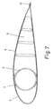
- a cover is situated, formed by frames (6) carried out in glass fibre or carbon fibre, which are glued to each other, being in turn glued to the ribs (5) and to the tube (2), as it can be observed in figure 7.
- the frames (6) that correspond to the sides determine a conformation (7) in a way corresponding to the contour bending of the tube (2), remaining defined in this conformation (7) some grooves (8) in accordance with the position and the thickness of the ribs (5), so that in the assembly the mentioned lateral frames (6) fit in, remaining embedded to the tube (2) and leaning at the same time on the ribs (5).
- each tract (1) is according to a unitary structural set.
- the tracts formed this way are joined for the blade composition, by means of fastenings (9) between the bushings (3) included in the tube tracts (2), establishing in turn the union of the respective frames (6) by means of some corresponding fastenings (10) regarding a metallic rib (11) that is included in the connection screwing between the bushings (3) according to what is observed in figures 5 and 6.
- the blade set is provided with a core with great rigidity, formed by the tube (2) in carbon fibre and with an elastic cover, made up of the glass fibre frames (6), whose constructive realization is also foreseen by means of taping at ⁇ 45° with which a maximum stretching capacity of the formed material is obtained.
- the composition in tracts (1) also allows the dimensional division of the blade into appropriate parts for the normal road transport, so that, for example, for lengths between 35 and 50 meters the composition is carried out in two tracts (1), as the realization of figures 1 to 6, while for lengths between 50 and 65 meters, the composition is carried out at least in three tracts (1), as the realization of figures 8 and 9.
- this wider part is in turn foreseen to be made up of an independent lateral tract (12), according to figures 10 and 11, so that for the transport this tract (12) can equally be disconnected, so that all the parts are inside the measures for transport under normal conditions.
- the blade is finished off at its end with a metal tip (13), to which a conductive cable (14) is included at the inside of the tube (2), so that the metallic tip (13) has the function of a lightning rod, being discharged through the cable (14) to the discharge collector to the earth.
- the lateral frames (6) are joined by means of being captured with a metal profile (15), which remains joined at the metal tip (13), so that this profile (15) serves to discharge the static electricity, being at the same time a lightning rod to discharge it through the metal tip (13) and the cable (14) towards the discharge collector to the earth.
Abstract
Aerogenerator blade which is formed by
assembling one, two or more longitudinal sections, each
of which comprises a core formed by a longitudinal
carbon-fiber tube (2) on which a series of carbon fiber
or fiberglass cross ribs (5) are mounted. A cover is
placed on said assembly, which is formed by fiberglass
or carbon-fiber housings (6) that are joined by gluing
and in relation to the ribs (5) and the tube (2).
Description
- In an aerogenerator, the energy that is obtained is a function of the rotor blade sweeping surface that receives the action from the wind, in such a way that up to now the biggest aerogenerators carried out are from 800 to 1000 kilowatt, which is obtained with some blades of about 30 meters length, i.e. with a sweeping surface in front of the wind of a diameter of about 60 meters.
- It is at least very problematic to surpass those measures with the construction of the blades used up to now for the following reasons:
- 1. - The conventional blades have a construction with an only shell which implies serious difficulties for the transport, since any length bigger than 30 meters forces to the use of special road transport on lorries.
- 2. - The aerogenerators are generally installed in mountain areas where the difficulty to access increases even more the transport problem.
- 3. - The conventional blades are being made in glass fibre material, which has a restricted resistance to fatigue and rigidity, conditioning the possibilities of their application to certain limitations.
-
- Everything gives rise to a conditioning that can be denominated "SIZE EFFECT", due to which the glass fibre monoshell blades cannot reach dimensions bigger than those already existing ones, which determines a practically unsurpassable barrier to reach with that shape constructive realizations of aerogenerators with more power than the existing ones.
- In a trial to make the use of aerogenerators of up to 5 megawatt feasible, German scientists are studying the possibility to install the needed big aerogenerators in the sea, which eliminates the problem of the road transport, provided the construction is carried out in places which are directly accessible to the sea; but the inconvenience of the dimensional limitations of the blades persists in function of their constructive shape and of the material used.
- In accordance with the present invention a blade for aerogenerators is proposed whose constructive realization solves in a satisfactory way the mentioned problems, allowing the construction of blades with a great length with an appropriate resistance to the efforts they have to support and moreover with a composition that allows the division in parts for the normal road transport.
- This blade, object of the invention, is formed by a set of adaptable longitudinal tracts, each of which includes a core formed by a carbon fibre tube with steel bushings inserted at the ends for the connections, incorporating in a solidary way on the mentioned pipe a series of traverse ribs of carbon fibre or glass fibre, while on the set some covers of glass fibre or carbon fibre are incorporated, which are glued to one another on the ribs and on the tube, forming a unitary structural set.
- This way a multi-shell blade is obtained, formed by tracts of a length that does not require overdimensioned facilities for the construction, being this length moreover appropriate to the effects of the normal transport possibility by lorry, while by means of the corresponding composition, blades can be formed of any longitudinal dimension.
- When the blade dimension determines a width at the base that is bigger than the acceptable measures for the normal road transport, the composition is in turn foreseen at the extreme area adjacent to the base of an independent lateral tract that can be disconnected from the rest for the transport.
- The shape of the ribs is according to the aerodynamic profile that corresponds to the traverse section of the blades, establishing the union of these ribs with the longitudinal pipe at a point that corresponds to 25 % of their length, i.e. at the point that coincides with the centre of gravity of the aerodynamic profile of the mentioned ribs, so that these do not create torsion on the pipe when the blades are operating.
- As there is no torsion, the constructive disposition of the set with the external covers embedded to the longitudinal tube, makes that this longitudinal tube, made of carbon fibre, and therefore very rigid, assumes all the responsibility of the load efforts; while the glass fibre covers, which are very elastic, only assume the effort of the aerodynamic function, having the blades consequently a great resistance to the efforts that have to be supported in their application. The elasticity of the covers is reached in its biggest degree by means of their constructive taping at ± 45° , with which the stretching capacity of the built material is maximum.
- In view of all this, this blade, object of the invention, certainly has some very advantageous features that confer it an own life and preferable character regarding the conventional blades used up to now in aerogenerators.
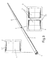
- Figure 1 represents an aerogenerator blade according to the object of the invention in perspective.
- Figure 2 is an exploded perspective of the same previously mentioned blade.
- Figure 3 is a perspective of the longitudinal tube of the blade structure with both details enlarged in section, corresponding to the base end and to the connectable ends of the component tracts.
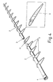
- Figure 4 is a perspective of the mentioned longitudinal blade tube with the traverse ribs incorporated, having extracted in enlarged detail the rib configuration.
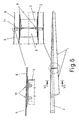
- Figure 5 is a lateral view of a blade with two tracts according to the object of the invention, having extracted an enlarged detail in section of the connection area of the tracts.
- Figure 6 is a lateral view of the same previously mentioned blade with the tracts joined, having extracted an enlarged detail in section of the area of the tract union and in turn a more enlarged detail of the part of correlative union of the covers.
- Figure 7 is a view in enlarged representation of the traverse section of the blade according to section VII-VII indicated in the previous figure.
- Figure 8 shows a perspective of a blade with three tracts according to the object of the invention.
- Figure 9 is a perspective of the same blade of the previous figure, with the component tracts separated.
- Figure 10 shows a perspective of a blade with three longitudinal tracts and a fourth lateral tract at the part that corresponds to the extreme area having a greater width.
- Figure 11 is a perspective of the same blade of the previous figure, with the component tract separated.
-
- The object of the invention refers to a blade for aerogenerators which is formed by one, two or more successively connectable tracts (1).
- Each of the mentioned tract (1) components is structured with a core formed by a longitudinal tube (2) carried out in carbon fibre, with inclusion of some steel bushings (3) and (3.1) solidarily inserted inside and outside into the joining ends, to establish through the interior bushings (3) the fastening between the mentioned tracts (1), while at the end that corresponds to the blade base, the respective tube (2) includes other bushings (4) and (4.1) for the fastening on the respective support in the aerogenerator by means of the external bushing (4.1).
- In solidary incorporation on the tube (2) some traverse ribs (5) are also installed, carried out in carbon fibre or glass fibre, these ribs are correlative to the aerodynamic profile of the blade.
- The mentioned ribs (5) are situated with regard to the tube (2) in such a way that the latter goes through a point that corresponds to 25 % of the length of the same, with which those ribs (5) remain mounted precisely by fixing through the point that coincides with the centre of gravity of the aerodynamic profile they form.
- This way the mentioned ribs (5) do not create torsion on the tube (2) by the effort of the blade originated by its operation, contrary to what happens with the blade used up to now, in which torsion efforts that affect the structure of the blade take place.
- On the set of the tube (2), and the ribs (5) a cover is situated, formed by frames (6) carried out in glass fibre or carbon fibre, which are glued to each other, being in turn glued to the ribs (5) and to the tube (2), as it can be observed in figure 7.
- As represented on figure 2, the frames (6) that correspond to the sides determine a conformation (7) in a way corresponding to the contour bending of the tube (2), remaining defined in this conformation (7) some grooves (8) in accordance with the position and the thickness of the ribs (5), so that in the assembly the mentioned lateral frames (6) fit in, remaining embedded to the tube (2) and leaning at the same time on the ribs (5).
- This disposition and the union gluing of all the parts makes that each tract (1) is according to a unitary structural set. The tracts formed this way are joined for the blade composition, by means of fastenings (9) between the bushings (3) included in the tube tracts (2), establishing in turn the union of the respective frames (6) by means of some corresponding fastenings (10) regarding a metallic rib (11) that is included in the connection screwing between the bushings (3) according to what is observed in figures 5 and 6.
- This way the blade set is provided with a core with great rigidity, formed by the tube (2) in carbon fibre and with an elastic cover, made up of the glass fibre frames (6), whose constructive realization is also foreseen by means of taping at ± 45° with which a maximum stretching capacity of the formed material is obtained.
- The mentioned features of the materials, together with the disposition of the frames (6) leaned on the ribs (5) and embedded to the tube (2) as well as the disposition of the ribs (5) in the assembly, in such a way that no torsion is provoked on the tube (2), make that the blade set behaves in its operating function assuming the tube (2) all the loading effort responsibility, while the frames (6) of the cover are only subjected to the effort of the aerodynamic function, having in consequence the blade a great resistance to the efforts that it has to bear during its application, with possibility of lengths that surpass the possibilities of the conventional blades.
- The composition in tracts (1) also allows the dimensional division of the blade into appropriate parts for the normal road transport, so that, for example, for lengths between 35 and 50 meters the composition is carried out in two tracts (1), as the realization of figures 1 to 6, while for lengths between 50 and 65 meters, the composition is carried out at least in three tracts (1), as the realization of figures 8 and 9.
- When for the constructive dimension the width of the blade at the extreme area of the base is of a dimension that surpasses the acceptable measures for the normal road transport, this wider part is in turn foreseen to be made up of an independent lateral tract (12), according to figures 10 and 11, so that for the transport this tract (12) can equally be disconnected, so that all the parts are inside the measures for transport under normal conditions.
- The blade is finished off at its end with a metal tip (13), to which a conductive cable (14) is included at the inside of the tube (2), so that the metallic tip (13) has the function of a lightning rod, being discharged through the cable (14) to the discharge collector to the earth.
- At the narrow blade edge the lateral frames (6) are joined by means of being captured with a metal profile (15), which remains joined at the metal tip (13), so that this profile (15) serves to discharge the static electricity, being at the same time a lightning rod to discharge it through the metal tip (13) and the cable (14) towards the discharge collector to the earth.
Claims (7)
- Aerogenerator blade, of the kind comprising a composition of longitudinal tracts successively connectable, characterized in that it is formed by a composition of at least two longitudinal tracts (1) each of which includes a core formed by a tube (2) of carbon fibre, on which solidarity a series of traverse ribs (5) of carbon fibre or glass fibre are incorporated, while an external cover formed by frames (6) of glass fibre or carbon fibre is situated over the whole thing being these frames glued to each other and with regard to the ribs (5) and the tube (2).
- Aerogenerator blade, according to the first claim, characterized in that the ribs (5) are situated in the assembly remaining crossed by the tube (2) at a point that corresponds to 25 % of the length of the mentioned ribs (5), coinciding with the centre of gravity of the aerodynamic profile of the same.
- Aerogenerator blade, according to the first claim, characterized in that the frames (6) which form the external cover determine a conformation (7) in correspondence with the peripheral bending of the tube (2), remaining defined in this conformation (7) some grooves (8) in correspondence with the position and the thickness of the ribs (5), so that in the assembly of the mentioned frames (6) they remain inserted and embedded to the tube (2).
- Aerogenerator blade, according to the first claim, characterized in that the tracts of the tube (2) include some steel bushings (3) solidarily inserted, the latter serve as means to establish the fastening between the tracts of the composition of the blade (1) during the assembly union.
- Aerogenerator blade, according to the first claim, characterized in that between the component tracts (1) which form the composition of the blade, a metallic rib (11) is included, on which the fastening of the respective frames (6) of the tracts (1) are situated in the corresponding assembly union.
- Aerogenerator blade, according to the first up to the fifth claims, characterized in that when the widest part of the blade surpasses a certain dimension, the mentioned part is formed including an independent lateral tract (12) that can be disconnected for the transport.
- Aerogenerator blade, according to the first up to the sixth claims, characterized in that at the narrow edge of the aerodynamic profile of the blade the frames (6) are joined by means of being captured with a metallic profile (15), which serves at the same time for the discharge of the static electricity and as a lightning rod.
Applications Claiming Priority (3)
| Application Number | Priority Date | Filing Date | Title |
|---|---|---|---|
| ES9901177 | 1999-05-31 | ||
| ES009901177A ES2178903B1 (en) | 1999-05-31 | 1999-05-31 | SHOVEL FOR AEROGENERATOR. |
| PCT/ES2000/000187 WO2000073651A1 (en) | 1999-05-31 | 2000-05-26 | Aerogenerator blade |
Publications (1)
| Publication Number | Publication Date |
|---|---|
| EP1184566A1 true EP1184566A1 (en) | 2002-03-06 |
Family
ID=8308628
Family Applications (1)
| Application Number | Title | Priority Date | Filing Date |
|---|---|---|---|
| EP00929568A Withdrawn EP1184566A1 (en) | 1999-05-31 | 2000-05-26 | Aerogenerator blade |
Country Status (3)
| Country | Link |
|---|---|
| EP (1) | EP1184566A1 (en) |
| ES (1) | ES2178903B1 (en) |
| WO (1) | WO2000073651A1 (en) |
Cited By (56)
| Publication number | Priority date | Publication date | Assignee | Title |
|---|---|---|---|---|
| WO2003104646A1 (en) * | 2002-06-05 | 2003-12-18 | Aloys Wobben | Rotor blade for a wind power plant |
| DE10235496A1 (en) * | 2002-08-02 | 2004-02-12 | Ge Wind Energy Gmbh | Method for making wind turbine blade comprises fitting connectors over joint between two sections of blade, gap between inner surfaces of connector and blade sections then being filled with resin |
| WO2004097215A1 (en) * | 2003-04-28 | 2004-11-11 | Aloys Wobben | Rotor blade of a wind energy facility |
| JP2005147086A (en) * | 2003-11-19 | 2005-06-09 | Fuji Heavy Ind Ltd | Blade of horizontal axis wind mill |
| FR2863319A1 (en) * | 2003-12-09 | 2005-06-10 | Ocea Sa | Wind generator`s blade for producing electricity, has ribs coupled to mast using sticking lip, and layer coupled to ribs by sticking lip, where sticking lip is constituted of bi-component polyurethane adhesive |
| EP1561947A2 (en) | 2004-02-05 | 2005-08-10 | Fuji Jukogyo Kabushiki Kaisha | Wind turbine blade transportable in sections |
| EP1584817A1 (en) * | 2004-04-07 | 2005-10-12 | Gamesa Eolica, S.A. (Sociedad Unipersonal) | Wind turbine blade |
| WO2006002621A1 (en) * | 2004-06-30 | 2006-01-12 | Vestas Wind Systems A/S | Wind turbine blades made of two separate sections, and method of assembly |
| WO2006005944A1 (en) * | 2004-07-12 | 2006-01-19 | Steven Peace | Modular construction for wind turbine blade |
| WO2006039953A1 (en) * | 2004-10-08 | 2006-04-20 | Eew Maschinenbau Gmbh | Rotor blade for a wind power system |
| WO2006103307A2 (en) | 2005-03-31 | 2006-10-05 | Gamesa Innovation And Technology, S.L. | Blade for wind-power generators |
| EP1760310A1 (en) * | 2002-06-05 | 2007-03-07 | Aloys Wobben | Rotor blade for a wind power plant |
| WO2007131937A1 (en) * | 2006-05-11 | 2007-11-22 | Wobben, Aloys | Rotor blade for a wind energy installation |
| WO2008086805A2 (en) * | 2007-01-16 | 2008-07-24 | Danmarks Tekniske Universitet | Reinforced blade for wind turbine |
| EP1965074A2 (en) | 2007-02-28 | 2008-09-03 | Gamesa Innovation And Technology, S.L. | A wind turbine multi-panel blade |
| EP2134963A1 (en) * | 2007-03-20 | 2009-12-23 | Myles L. Baker | Lightweight composite truss wind turbine blade |
| WO2010026903A1 (en) * | 2008-09-04 | 2010-03-11 | 三菱重工業株式会社 | Wind wheel blade |
| WO2009156064A3 (en) * | 2008-06-27 | 2010-05-14 | Repower Systems Ag | Method and production of a rotor blade for wind energy plant |
| US20100122442A1 (en) * | 2008-11-14 | 2010-05-20 | General Electric Company | Turbine blade fabrication |
| EP2199604A2 (en) * | 2008-12-18 | 2010-06-23 | General Electric Company | A blade module, a modular rotor blade and a method for assembling a modular rotor blade |
| WO2009130467A3 (en) * | 2008-04-24 | 2010-09-23 | Blade Dynamics Limited | A wind turbine blade |
| WO2010013024A3 (en) * | 2008-08-01 | 2010-11-04 | Vestas Wind Systems A/S | Rotor blade extension portion having a skin located over a framework |
| CN101943106A (en) * | 2009-07-05 | 2011-01-12 | 宿迁雅臣工程尼龙有限公司 | High-molecular composite blade for 500KW-below three-blade wind turbine |
| WO2011006800A1 (en) * | 2009-07-16 | 2011-01-20 | Astrium Sas | Device for assembling sections of wind-turbine blades and method for linking sections of wind-turbine blades |
| US20110123343A1 (en) * | 2009-11-24 | 2011-05-26 | Ronner David E | Wind turbine blade and methods, apparatus and materials for fabrication in the field |
| CN102094748A (en) * | 2009-12-14 | 2011-06-15 | 通用电气公司 | A fluid turbine blade and method of providing the same |
| WO2011094912A1 (en) * | 2010-02-08 | 2011-08-11 | 国能风力发电有限公司 | Wind-wheel blade for vertical axis wind power generator axis |
| WO2011098506A1 (en) * | 2010-02-10 | 2011-08-18 | Vestas Wind Systems A/S | A sectional blade |
| WO2011149990A2 (en) | 2010-05-24 | 2011-12-01 | Arendt Cory P | Segmented wind turbine blades with truss connection regions, and associated systems and methods |
| WO2012031976A1 (en) * | 2010-09-10 | 2012-03-15 | Wobben, Aloys | Removable rotor blade tip |
| CN102483032A (en) * | 2009-04-13 | 2012-05-30 | 极流制造股份有限公司 | Wind turbine blade and method of constructing same |
| CN102606420A (en) * | 2012-04-16 | 2012-07-25 | 国电联合动力技术有限公司 | Large wind driven power generator and sectional type blade thereof |
| EP2492497A2 (en) | 2011-02-24 | 2012-08-29 | Gamesa Innovation & Technology, S.L. | An improved wind turbine multi-panel blade |
| CN1755102B (en) * | 2004-09-30 | 2012-11-14 | 通用电气公司 | Multi-piece wind turbine rotor blades and wind turbines incorporating same |
| EP2525081A1 (en) * | 2010-01-11 | 2012-11-21 | Sinovel Wind Group Co., Ltd | Segmented wind wheel blade for wind generating set and assemblying method thereof |
| EP2527128A2 (en) | 2011-05-24 | 2012-11-28 | Gamesa Innovation & Technology, S.L. | A bonding method for a wind turbine multi-panel blade |
| CN101828030B (en) * | 2007-09-11 | 2012-12-26 | 刀具动力学有限公司 | Wind turbine blade |
| US8454318B2 (en) | 2006-12-15 | 2013-06-04 | Bladena Aps | Reinforced aerodynamic profile |
| EP2617992A3 (en) * | 2003-06-09 | 2013-08-28 | Sinfonia Technology Co., Ltd. | Vertical axis type wind power station |
| EP2341238A3 (en) * | 2009-12-31 | 2014-01-15 | General Electric Company | Rotor blade for use with a wind turbine |
| US8632312B2 (en) | 2007-01-25 | 2014-01-21 | Bladena Aps | Reinforced blade for wind turbine |
| US8807953B2 (en) | 2008-06-24 | 2014-08-19 | Bladena Aps | Reinforced wind turbine blade |
| EP2770197A3 (en) * | 2003-09-29 | 2014-09-17 | Vestas Wind Systems A/S | Wind turbine blade, wind turbine, method of providing lightning receptor means to a wind turbine blade and use hereof |
| WO2014202689A1 (en) * | 2013-06-20 | 2014-12-24 | Lm Wp Patent Holding A/S | A tribrid wind turbine blade |
| US20150003991A1 (en) * | 2013-06-28 | 2015-01-01 | General Electric Company | Modular extensions for wind turbine rotor blades |
| DK178479B1 (en) * | 2007-09-17 | 2016-04-11 | Gen Electric | SYSTEM AND PROCEDURE FOR COLLECTING WINDOW EXPERIENCES |
| DK178485B1 (en) * | 2011-05-25 | 2016-04-11 | Gen Electric | Rotor blade section and method for assembling a rotor blade for a wind turbine |
| US9416768B2 (en) | 2009-12-02 | 2016-08-16 | Bladena Aps | Reinforced airfoil shaped body |
| US9470205B2 (en) | 2013-03-13 | 2016-10-18 | Vestas Wind Systems A/S | Wind turbine blades with layered, multi-component spars, and associated systems and methods |
| US9500179B2 (en) | 2010-05-24 | 2016-11-22 | Vestas Wind Systems A/S | Segmented wind turbine blades with truss connection regions, and associated systems and methods |
| US9518558B2 (en) | 2008-12-05 | 2016-12-13 | Vestas Wind Systems A/S | Efficient wind turbine blades, wind turbine blade structures, and associated systems and methods of manufacture, assembly and use |
| WO2018007403A1 (en) * | 2016-07-05 | 2018-01-11 | Peter Lutz | Rotor blade and rotor for megawatt wind turbines |
| WO2018015098A1 (en) * | 2016-07-22 | 2018-01-25 | Wobben Properties Gmbh | Wind turbine rotor blade and wind turbine rotor blade tip |
| EP1815137B1 (en) | 2004-11-24 | 2018-09-05 | Siemens Aktiengesellschaft | Windmill blade |
| US11313346B2 (en) * | 2018-06-08 | 2022-04-26 | Siemens Gamesa Renewable Energy A/S | Method of manufacturing wind turbine rotor blades |
| CN115163555A (en) * | 2022-07-18 | 2022-10-11 | 江苏航宇航空装备制造有限公司 | Carbon fiber blade used at low temperature |
Families Citing this family (8)
| Publication number | Priority date | Publication date | Assignee | Title |
|---|---|---|---|---|
| US7637721B2 (en) * | 2005-07-29 | 2009-12-29 | General Electric Company | Methods and apparatus for producing wind energy with reduced wind turbine noise |
| ES2319599B1 (en) * | 2007-01-08 | 2010-01-26 | Guillermo Petri Larrea | REVERSIBLE SECTIONING SYSTEM IN VARIOUS PARTS OF AEROGENERATING BLADES. |
| ES2333499B1 (en) * | 2007-09-11 | 2010-10-15 | Manuel Torres Martinez | SHOVEL FOR AEROGENERATOR. |
| ES2342998B1 (en) * | 2009-01-19 | 2011-06-27 | Manuel Torres Martinez | AIRLINER SHOVEL. |
| ES2392523B2 (en) | 2011-05-13 | 2013-05-16 | Investigaciones Y Desarrollos Eólicos, S.L. | SYSTEM OF UNION OF COMPONENT SECTIONS OF AEROGENERATOR SHOES. |
| CN102797645B (en) * | 2012-09-04 | 2015-04-01 | 河海大学常州校区 | Wind-driven generator blade with keel structure |
| CN106270077A (en) * | 2016-08-31 | 2017-01-04 | 三重型能源装备有限公司 | Eyelid covering and the manufacture method of fan blade, fan blade |
| DE102017124861A1 (en) | 2017-10-24 | 2019-04-25 | Wobben Properties Gmbh | Rotor blade of a wind turbine and method for its design |
Family Cites Families (9)
| Publication number | Priority date | Publication date | Assignee | Title |
|---|---|---|---|---|
| GB707620A (en) * | 1952-02-06 | 1954-04-21 | Ernst Einar Forsman | Improvements in or relating to wings for wind motors |
| US3400904A (en) * | 1966-12-19 | 1968-09-10 | James R. Bede | Airfoil construction |
| DE3037677A1 (en) * | 1980-10-04 | 1982-05-19 | M.A.N. Maschinenfabrik Augsburg-Nürnberg AG, 8000 München | Wind-driven machine rotor wing - has spar formed by axial mast, to which are secured profiled strips via triangular gusset plates |
| FR2588822B1 (en) * | 1985-10-22 | 1988-08-26 | Courthieu Sa Georges | WING FOR LIGHT AIRCRAFT |
| NL8602097A (en) * | 1986-08-18 | 1988-03-16 | Strijense Kunststof Technieken | WIND TURBINE ROTOR WITH TWO ROTOR BLADES. |
| US4739954A (en) * | 1986-12-29 | 1988-04-26 | Hamilton Terry W | Over-lap rib joint |
| US4976587A (en) * | 1988-07-20 | 1990-12-11 | Dwr Wind Technologies Inc. | Composite wind turbine rotor blade and method for making same |
| DK9400343U4 (en) * | 1994-09-07 | 1995-10-13 | Bonus Energy As | Lightning protection of wind turbine wings |
| ES2144336B1 (en) * | 1996-11-15 | 2000-12-01 | Torres Martinez M | BLADE FOR WIND TURBINE. |
-
1999
- 1999-05-31 ES ES009901177A patent/ES2178903B1/en not_active Expired - Lifetime
-
2000
- 2000-05-26 EP EP00929568A patent/EP1184566A1/en not_active Withdrawn
- 2000-05-26 WO PCT/ES2000/000187 patent/WO2000073651A1/en not_active Application Discontinuation
Non-Patent Citations (1)
| Title |
|---|
| See references of WO0073651A1 * |
Cited By (113)
| Publication number | Priority date | Publication date | Assignee | Title |
|---|---|---|---|---|
| EP1760310A1 (en) * | 2002-06-05 | 2007-03-07 | Aloys Wobben | Rotor blade for a wind power plant |
| US8100663B2 (en) | 2002-06-05 | 2012-01-24 | Aloys Wobben | Rotor blade for a wind power plant |
| EP2280164A3 (en) * | 2002-06-05 | 2012-01-04 | Aloys Wobben | Wind power plant |
| EP2280163A3 (en) * | 2002-06-05 | 2012-01-04 | Aloys Wobben | Wind power plant and rotor blade for a wind power plant |
| EP2284389A3 (en) * | 2002-06-05 | 2012-01-04 | Aloys Wobben | Rotor blade for a wind power plant |
| EP2280165A3 (en) * | 2002-06-05 | 2012-01-04 | Aloys Wobben | Wind power plant |
| US7914261B2 (en) | 2002-06-05 | 2011-03-29 | Aloys Wobben | Rotor blade for a wind power plant |
| WO2003104646A1 (en) * | 2002-06-05 | 2003-12-18 | Aloys Wobben | Rotor blade for a wind power plant |
| US7708530B2 (en) | 2002-06-05 | 2010-05-04 | Aloys Wobben | Rotor blade for a wind power plant |
| US7357624B2 (en) | 2002-06-05 | 2008-04-15 | Aloys Wobben | Rotor blade for a wind power plant |
| DE10235496B4 (en) * | 2002-08-02 | 2015-07-30 | General Electric Co. | Method for producing a rotor blade, rotor blade and wind energy plant |
| DE10235496A1 (en) * | 2002-08-02 | 2004-02-12 | Ge Wind Energy Gmbh | Method for making wind turbine blade comprises fitting connectors over joint between two sections of blade, gap between inner surfaces of connector and blade sections then being filled with resin |
| WO2004097215A1 (en) * | 2003-04-28 | 2004-11-11 | Aloys Wobben | Rotor blade of a wind energy facility |
| JP2010043650A (en) * | 2003-04-28 | 2010-02-25 | Aloys Wobben | Rotor blade for wind power facility |
| EP2617992A3 (en) * | 2003-06-09 | 2013-08-28 | Sinfonia Technology Co., Ltd. | Vertical axis type wind power station |
| EP2770197A3 (en) * | 2003-09-29 | 2014-09-17 | Vestas Wind Systems A/S | Wind turbine blade, wind turbine, method of providing lightning receptor means to a wind turbine blade and use hereof |
| JP2005147086A (en) * | 2003-11-19 | 2005-06-09 | Fuji Heavy Ind Ltd | Blade of horizontal axis wind mill |
| FR2863319A1 (en) * | 2003-12-09 | 2005-06-10 | Ocea Sa | Wind generator`s blade for producing electricity, has ribs coupled to mast using sticking lip, and layer coupled to ribs by sticking lip, where sticking lip is constituted of bi-component polyurethane adhesive |
| JP4580169B2 (en) * | 2004-02-05 | 2010-11-10 | 富士重工業株式会社 | Split blade for windmill and lightning protection device for windmill |
| JP2005220805A (en) * | 2004-02-05 | 2005-08-18 | Fuji Heavy Ind Ltd | Split type blade for windmill and lightning arrester for windmill |
| EP1561947A3 (en) * | 2004-02-05 | 2010-10-27 | Fuji Jukogyo Kabushiki Kaisha | Wind turbine blade transportable in sections |
| EP1561947A2 (en) | 2004-02-05 | 2005-08-10 | Fuji Jukogyo Kabushiki Kaisha | Wind turbine blade transportable in sections |
| CN1957178B (en) * | 2004-04-07 | 2011-12-07 | 歌美飒创新技术公司 | Wind turbine blade |
| EP1584817A1 (en) * | 2004-04-07 | 2005-10-12 | Gamesa Eolica, S.A. (Sociedad Unipersonal) | Wind turbine blade |
| WO2006002621A1 (en) * | 2004-06-30 | 2006-01-12 | Vestas Wind Systems A/S | Wind turbine blades made of two separate sections, and method of assembly |
| US8348622B2 (en) | 2004-06-30 | 2013-01-08 | Vestas Wind Systems A/S | Wind turbine blades made of two separate sections, and method of assembly |
| CN1977108B (en) * | 2004-06-30 | 2011-09-14 | 维斯塔斯风力系统有限公司 | Wind turbine blades made of two separate sections, and method of assembly |
| AU2005261490B2 (en) * | 2004-07-12 | 2012-01-19 | Paul Marsh | Modular construction for wind turbine blade |
| US8070451B2 (en) | 2004-07-12 | 2011-12-06 | Steven Peace | Modular construction for wind turbine blade |
| WO2006005944A1 (en) * | 2004-07-12 | 2006-01-19 | Steven Peace | Modular construction for wind turbine blade |
| CN1755102B (en) * | 2004-09-30 | 2012-11-14 | 通用电气公司 | Multi-piece wind turbine rotor blades and wind turbines incorporating same |
| WO2006039953A1 (en) * | 2004-10-08 | 2006-04-20 | Eew Maschinenbau Gmbh | Rotor blade for a wind power system |
| EP1815137B1 (en) | 2004-11-24 | 2018-09-05 | Siemens Aktiengesellschaft | Windmill blade |
| WO2006103307A2 (en) | 2005-03-31 | 2006-10-05 | Gamesa Innovation And Technology, S.L. | Blade for wind-power generators |
| AU2007251569B2 (en) * | 2006-05-11 | 2010-02-25 | Wobben, Aloys | Rotor blade for a wind energy installation |
| US8192170B2 (en) | 2006-05-11 | 2012-06-05 | Aloys Wobben | Rotor blade for a wind energy installation |
| CN101438053B (en) * | 2006-05-11 | 2011-09-28 | 艾劳埃斯·乌本 | Rotor blade for a wind energy installation |
| WO2007131937A1 (en) * | 2006-05-11 | 2007-11-22 | Wobben, Aloys | Rotor blade for a wind energy installation |
| US8454318B2 (en) | 2006-12-15 | 2013-06-04 | Bladena Aps | Reinforced aerodynamic profile |
| US8485786B2 (en) | 2007-01-16 | 2013-07-16 | Bladena Aps | Reinforced blade for wind turbine |
| WO2008086805A3 (en) * | 2007-01-16 | 2008-12-24 | Univ Danmarks Tekniske | Reinforced blade for wind turbine |
| CN101611225B (en) * | 2007-01-16 | 2012-05-23 | 丹麦技术大学 | Reinforced blade for wind turbine |
| WO2008086805A2 (en) * | 2007-01-16 | 2008-07-24 | Danmarks Tekniske Universitet | Reinforced blade for wind turbine |
| US8632312B2 (en) | 2007-01-25 | 2014-01-21 | Bladena Aps | Reinforced blade for wind turbine |
| US8262361B2 (en) | 2007-02-28 | 2012-09-11 | Gamesa Innovation & Technology, S.L. | Wind turbine multi-panel blade |
| CN101255847B (en) * | 2007-02-28 | 2012-06-06 | 歌美飒创新技术公司 | Wind turbine multi-panel blade |
| EP1965074A2 (en) | 2007-02-28 | 2008-09-03 | Gamesa Innovation And Technology, S.L. | A wind turbine multi-panel blade |
| EP2134963A4 (en) * | 2007-03-20 | 2013-02-27 | Modular Wind Energy Inc | Lightweight composite truss wind turbine blade |
| EP2134963A1 (en) * | 2007-03-20 | 2009-12-23 | Myles L. Baker | Lightweight composite truss wind turbine blade |
| CN101828030B (en) * | 2007-09-11 | 2012-12-26 | 刀具动力学有限公司 | Wind turbine blade |
| US8425195B2 (en) | 2007-09-11 | 2013-04-23 | Blade Dynamics Limited | Wind turbine blade |
| US8696317B2 (en) | 2007-09-11 | 2014-04-15 | Blade Dynamics Limited | Wind turbine blade |
| DK178479B1 (en) * | 2007-09-17 | 2016-04-11 | Gen Electric | SYSTEM AND PROCEDURE FOR COLLECTING WINDOW EXPERIENCES |
| DE102008037367B4 (en) | 2007-09-17 | 2020-01-23 | General Electric Co. | System and method for connecting rotor blades |
| WO2009130467A3 (en) * | 2008-04-24 | 2010-09-23 | Blade Dynamics Limited | A wind turbine blade |
| US9133818B2 (en) | 2008-04-24 | 2015-09-15 | Blade Dynamics Limited | Wind turbine blade |
| US9784240B2 (en) | 2008-06-24 | 2017-10-10 | Bladena Solutions Aps | Reinforced wind turbine blade |
| US8807953B2 (en) | 2008-06-24 | 2014-08-19 | Bladena Aps | Reinforced wind turbine blade |
| WO2009156064A3 (en) * | 2008-06-27 | 2010-05-14 | Repower Systems Ag | Method and production of a rotor blade for wind energy plant |
| US8393865B2 (en) | 2008-08-01 | 2013-03-12 | Vestas Wind Systems A/S | Rotor blade extension portion having a skin located over a framework |
| WO2010013024A3 (en) * | 2008-08-01 | 2010-11-04 | Vestas Wind Systems A/S | Rotor blade extension portion having a skin located over a framework |
| WO2010026903A1 (en) * | 2008-09-04 | 2010-03-11 | 三菱重工業株式会社 | Wind wheel blade |
| JP2010059884A (en) * | 2008-09-04 | 2010-03-18 | Mitsubishi Heavy Ind Ltd | Wind turbine blade |
| EP2320082A4 (en) * | 2008-09-04 | 2013-12-25 | Mitsubishi Heavy Ind Ltd | Wind wheel blade |
| EP2320082A1 (en) * | 2008-09-04 | 2011-05-11 | Mitsubishi Heavy Industries, Ltd. | Wind wheel blade |
| US20100122442A1 (en) * | 2008-11-14 | 2010-05-20 | General Electric Company | Turbine blade fabrication |
| US8510947B2 (en) * | 2008-11-14 | 2013-08-20 | General Electric Company | Turbine blade fabrication |
| US9845787B2 (en) | 2008-12-05 | 2017-12-19 | Vestas Wind Systems A/S | Efficient wind turbine blades, wind turbine blade structures, and associated systems and methods of manufacture, assembly and use |
| US9518558B2 (en) | 2008-12-05 | 2016-12-13 | Vestas Wind Systems A/S | Efficient wind turbine blades, wind turbine blade structures, and associated systems and methods of manufacture, assembly and use |
| EP2199604A3 (en) * | 2008-12-18 | 2013-03-06 | General Electric Company | A blade module, a modular rotor blade and a method for assembling a modular rotor blade |
| EP2199604A2 (en) * | 2008-12-18 | 2010-06-23 | General Electric Company | A blade module, a modular rotor blade and a method for assembling a modular rotor blade |
| CN102483032B (en) * | 2009-04-13 | 2014-07-23 | 极流制造股份有限公司 | Wind turbine blade and method of constructing same |
| CN102483032A (en) * | 2009-04-13 | 2012-05-30 | 极流制造股份有限公司 | Wind turbine blade and method of constructing same |
| CN101943106A (en) * | 2009-07-05 | 2011-01-12 | 宿迁雅臣工程尼龙有限公司 | High-molecular composite blade for 500KW-below three-blade wind turbine |
| WO2011006800A1 (en) * | 2009-07-16 | 2011-01-20 | Astrium Sas | Device for assembling sections of wind-turbine blades and method for linking sections of wind-turbine blades |
| FR2948154A1 (en) * | 2009-07-16 | 2011-01-21 | Astrium Sas | DEVICE FOR ASSEMBLING WINDMILL BLADE RODS AND METHOD FOR CONNECTING WINDMILL BLADE TRUNCONS |
| US9169825B2 (en) | 2009-07-16 | 2015-10-27 | Astrium Sas | Device for assembling sections of wind-turbine blades and method for linking sections of wind-turbine blades |
| US20110123343A1 (en) * | 2009-11-24 | 2011-05-26 | Ronner David E | Wind turbine blade and methods, apparatus and materials for fabrication in the field |
| US9416768B2 (en) | 2009-12-02 | 2016-08-16 | Bladena Aps | Reinforced airfoil shaped body |
| EP2333319B1 (en) | 2009-12-14 | 2016-11-02 | General Electric Company | A fluid turbine blade and method of providing the same |
| US8167570B2 (en) * | 2009-12-14 | 2012-05-01 | General Electric Company | Fluid turbine blade and method of providing the same |
| CN102094748A (en) * | 2009-12-14 | 2011-06-15 | 通用电气公司 | A fluid turbine blade and method of providing the same |
| CN102094748B (en) * | 2009-12-14 | 2014-08-20 | 通用电气公司 | A fluid turbine blade and method of providing the same |
| EP2333319A3 (en) * | 2009-12-14 | 2013-12-11 | General Electric Company | A fluid turbine blade and method of providing the same |
| EP2341238A3 (en) * | 2009-12-31 | 2014-01-15 | General Electric Company | Rotor blade for use with a wind turbine |
| EP2525081A1 (en) * | 2010-01-11 | 2012-11-21 | Sinovel Wind Group Co., Ltd | Segmented wind wheel blade for wind generating set and assemblying method thereof |
| EP2525081A4 (en) * | 2010-01-11 | 2013-07-24 | Sinovel Wind Group Co Ltd | Segmented wind wheel blade for wind generating set and assemblying method thereof |
| WO2011094912A1 (en) * | 2010-02-08 | 2011-08-11 | 国能风力发电有限公司 | Wind-wheel blade for vertical axis wind power generator axis |
| WO2011098506A1 (en) * | 2010-02-10 | 2011-08-18 | Vestas Wind Systems A/S | A sectional blade |
| US9255566B2 (en) | 2010-02-10 | 2016-02-09 | Vestas Wind Systems A/S | Sectional blade |
| US9500179B2 (en) | 2010-05-24 | 2016-11-22 | Vestas Wind Systems A/S | Segmented wind turbine blades with truss connection regions, and associated systems and methods |
| WO2011149990A2 (en) | 2010-05-24 | 2011-12-01 | Arendt Cory P | Segmented wind turbine blades with truss connection regions, and associated systems and methods |
| EP2577051A4 (en) * | 2010-05-24 | 2015-11-18 | Vestas Wind Sys As | Segmented wind turbine blades with truss connection regions, and associated systems and methods |
| US9371817B2 (en) | 2010-09-10 | 2016-06-21 | Wobben Properties Gmbh | Removable rotor blade tip |
| WO2012031976A1 (en) * | 2010-09-10 | 2012-03-15 | Wobben, Aloys | Removable rotor blade tip |
| US8967976B2 (en) | 2011-02-24 | 2015-03-03 | Gamesa Innovation & Technology, S.L. | Wind turbine with multi-panel blade |
| EP2492497A2 (en) | 2011-02-24 | 2012-08-29 | Gamesa Innovation & Technology, S.L. | An improved wind turbine multi-panel blade |
| EP2527128A2 (en) | 2011-05-24 | 2012-11-28 | Gamesa Innovation & Technology, S.L. | A bonding method for a wind turbine multi-panel blade |
| DK178485B1 (en) * | 2011-05-25 | 2016-04-11 | Gen Electric | Rotor blade section and method for assembling a rotor blade for a wind turbine |
| CN102606420A (en) * | 2012-04-16 | 2012-07-25 | 国电联合动力技术有限公司 | Large wind driven power generator and sectional type blade thereof |
| CN102606420B (en) * | 2012-04-16 | 2014-12-10 | 国电联合动力技术有限公司 | Large wind driven power generator and sectional type blade thereof |
| US9470205B2 (en) | 2013-03-13 | 2016-10-18 | Vestas Wind Systems A/S | Wind turbine blades with layered, multi-component spars, and associated systems and methods |
| CN105283666B (en) * | 2013-06-20 | 2018-11-30 | Lm Wp 专利控股有限公司 | Triple mixing wind turbine blades |
| CN105283666A (en) * | 2013-06-20 | 2016-01-27 | Lmwp专利控股有限公司 | A tribrid wind turbine blade |
| US20160108736A1 (en) * | 2013-06-20 | 2016-04-21 | Lm Wp Patent Holding A/S | A tribrid wind turbine blade |
| WO2014202689A1 (en) * | 2013-06-20 | 2014-12-24 | Lm Wp Patent Holding A/S | A tribrid wind turbine blade |
| US10947852B2 (en) | 2013-06-20 | 2021-03-16 | Lm Wp Patent Holding A/S | Tribrid wind turbine blade |
| US20150003991A1 (en) * | 2013-06-28 | 2015-01-01 | General Electric Company | Modular extensions for wind turbine rotor blades |
| WO2018007403A1 (en) * | 2016-07-05 | 2018-01-11 | Peter Lutz | Rotor blade and rotor for megawatt wind turbines |
| WO2018015098A1 (en) * | 2016-07-22 | 2018-01-25 | Wobben Properties Gmbh | Wind turbine rotor blade and wind turbine rotor blade tip |
| US11313346B2 (en) * | 2018-06-08 | 2022-04-26 | Siemens Gamesa Renewable Energy A/S | Method of manufacturing wind turbine rotor blades |
| CN115163555A (en) * | 2022-07-18 | 2022-10-11 | 江苏航宇航空装备制造有限公司 | Carbon fiber blade used at low temperature |
| CN115163555B (en) * | 2022-07-18 | 2024-02-13 | 江苏航宇航空装备制造有限公司 | Carbon fiber blade used at low temperature |
Also Published As
| Publication number | Publication date |
|---|---|
| ES2178903B1 (en) | 2004-03-16 |
| WO2000073651A1 (en) | 2000-12-07 |
| ES2178903A1 (en) | 2003-01-01 |
Similar Documents
| Publication | Publication Date | Title |
|---|---|---|
| EP1184566A1 (en) | Aerogenerator blade | |
| US8807839B2 (en) | Synthetic resin bearing for photovoltaic tracking system | |
| CN106907292B (en) | Wind turbine rotor blade | |
| CN102465827A (en) | Noise reducer for rotor blade in wind turbine | |
| EP2697047B1 (en) | Wind turbine blade comprising cylindrical metal inserts in a root region thereof | |
| AU2012314345A1 (en) | Blade for wind turbine and method of assembly of the blade | |
| US20190024629A1 (en) | Rotor Blade for a Wind Turbine | |
| KR20210015857A (en) | Vertical shaft windmill and wind power generator and lighting equipment equipped with it | |
| CN112888852A (en) | Lightning protection for wind turbine blades | |
| AU2010251465B2 (en) | Fan blade | |
| KR101123345B1 (en) | a wind turbine with a front side fixing type generator | |
| EP3894689B1 (en) | Segmented rotor blade having maximized overall pre-bend via an increased pre-bend in a blade tip segment thereof | |
| DE102010037706A1 (en) | Mast for supporting rotor of wind turbine, has mast main structure whose flexural rigidity is greater along direction perpendicular to longitudinal axis of the mast main structure | |
| CN116250174A (en) | D-shaped torque tube and bearing assembly | |
| CN217583416U (en) | Assembled aluminum alloy antidetonation mounting system | |
| CN217501270U (en) | Novel fan-shaped tent framework and fan-shaped tent | |
| CN216231554U (en) | Cast type guide arm for air suspension | |
| CN211474335U (en) | Tower and wind generating set | |
| CN215254047U (en) | Lateral extension frame for automatic telescopic canopy | |
| CN215956312U (en) | Foldable photovoltaic support of integration | |
| CN209896987U (en) | Saddle type fixed photovoltaic support | |
| CN217027792U (en) | Gutter board mounting structure that eavess | |
| CA2855493A1 (en) | Fluid driven turbine blade and turbine using same | |
| KR102334528B1 (en) | A blade of wind power generator | |
| CN216922364U (en) | Hollow pipe of wind turbine generator gearbox |
Legal Events
| Date | Code | Title | Description |
|---|---|---|---|
| PUAI | Public reference made under article 153(3) epc to a published international application that has entered the european phase |
Free format text: ORIGINAL CODE: 0009012 |
|
| 17P | Request for examination filed |
Effective date: 20011219 |
|
| AK | Designated contracting states |
Kind code of ref document: A1 Designated state(s): AT BE CH CY DE DK ES FI FR GB GR IE IT LI LU MC NL PT SE |
|
| STAA | Information on the status of an ep patent application or granted ep patent |
Free format text: STATUS: THE APPLICATION HAS BEEN WITHDRAWN |
|
| 18W | Application withdrawn |
Effective date: 20030123 |