EP0947693A2 - Rotorblatt für eine Windkraftanlage - Google Patents
Rotorblatt für eine Windkraftanlage Download PDFInfo
- Publication number
- EP0947693A2 EP0947693A2 EP99104853A EP99104853A EP0947693A2 EP 0947693 A2 EP0947693 A2 EP 0947693A2 EP 99104853 A EP99104853 A EP 99104853A EP 99104853 A EP99104853 A EP 99104853A EP 0947693 A2 EP0947693 A2 EP 0947693A2
- Authority
- EP
- European Patent Office
- Prior art keywords
- profile
- rotor blade
- wing
- blade according
- area
- Prior art date
- Legal status (The legal status is an assumption and is not a legal conclusion. Google has not performed a legal analysis and makes no representation as to the accuracy of the status listed.)
- Withdrawn
Links
- 230000000694 effects Effects 0.000 claims description 13
- 238000000926 separation method Methods 0.000 claims description 13
- 230000008859 change Effects 0.000 claims description 3
- 230000009467 reduction Effects 0.000 claims description 3
- 238000013016 damping Methods 0.000 abstract description 8
- 238000005457 optimization Methods 0.000 description 5
- 238000011161 development Methods 0.000 description 3
- 230000018109 developmental process Effects 0.000 description 3
- 238000000034 method Methods 0.000 description 3
- 230000008569 process Effects 0.000 description 3
- 230000001052 transient effect Effects 0.000 description 3
- 230000007704 transition Effects 0.000 description 3
- 238000000418 atomic force spectrum Methods 0.000 description 2
- 230000015572 biosynthetic process Effects 0.000 description 2
- 230000005284 excitation Effects 0.000 description 2
- 238000009434 installation Methods 0.000 description 2
- 238000004519 manufacturing process Methods 0.000 description 2
- 230000004048 modification Effects 0.000 description 2
- 238000012986 modification Methods 0.000 description 2
- 238000012549 training Methods 0.000 description 2
- 238000012935 Averaging Methods 0.000 description 1
- 239000004793 Polystyrene Substances 0.000 description 1
- 239000000853 adhesive Substances 0.000 description 1
- 238000004026 adhesive bonding Methods 0.000 description 1
- 230000001070 adhesive effect Effects 0.000 description 1
- 239000011324 bead Substances 0.000 description 1
- 238000005452 bending Methods 0.000 description 1
- 230000005540 biological transmission Effects 0.000 description 1
- 238000007664 blowing Methods 0.000 description 1
- 239000003795 chemical substances by application Substances 0.000 description 1
- 238000010073 coating (rubber) Methods 0.000 description 1
- 238000010276 construction Methods 0.000 description 1
- 230000007423 decrease Effects 0.000 description 1
- 230000001419 dependent effect Effects 0.000 description 1
- 238000009826 distribution Methods 0.000 description 1
- 239000004744 fabric Substances 0.000 description 1
- 239000003365 glass fiber Substances 0.000 description 1
- 230000006872 improvement Effects 0.000 description 1
- 229920002223 polystyrene Polymers 0.000 description 1
- 230000008961 swelling Effects 0.000 description 1
- 229920003002 synthetic resin Polymers 0.000 description 1
- 239000000057 synthetic resin Substances 0.000 description 1
Images

Classifications
-
- F—MECHANICAL ENGINEERING; LIGHTING; HEATING; WEAPONS; BLASTING
- F03—MACHINES OR ENGINES FOR LIQUIDS; WIND, SPRING, OR WEIGHT MOTORS; PRODUCING MECHANICAL POWER OR A REACTIVE PROPULSIVE THRUST, NOT OTHERWISE PROVIDED FOR
- F03D—WIND MOTORS
- F03D1/00—Wind motors with rotation axis substantially parallel to the air flow entering the rotor
- F03D1/06—Rotors
- F03D1/0608—Rotors characterised by their aerodynamic shape
- F03D1/0633—Rotors characterised by their aerodynamic shape of the blades
- F03D1/0641—Rotors characterised by their aerodynamic shape of the blades of the section profile of the blades, i.e. aerofoil profile
-
- F—MECHANICAL ENGINEERING; LIGHTING; HEATING; WEAPONS; BLASTING
- F05—INDEXING SCHEMES RELATING TO ENGINES OR PUMPS IN VARIOUS SUBCLASSES OF CLASSES F01-F04
- F05B—INDEXING SCHEME RELATING TO WIND, SPRING, WEIGHT, INERTIA OR LIKE MOTORS, TO MACHINES OR ENGINES FOR LIQUIDS COVERED BY SUBCLASSES F03B, F03D AND F03G
- F05B2240/00—Components
- F05B2240/20—Rotors
- F05B2240/21—Rotors for wind turbines
- F05B2240/221—Rotors for wind turbines with horizontal axis
- F05B2240/2213—Rotors for wind turbines with horizontal axis and with the rotor downwind from the yaw pivot axis
-
- F—MECHANICAL ENGINEERING; LIGHTING; HEATING; WEAPONS; BLASTING
- F05—INDEXING SCHEMES RELATING TO ENGINES OR PUMPS IN VARIOUS SUBCLASSES OF CLASSES F01-F04
- F05B—INDEXING SCHEME RELATING TO WIND, SPRING, WEIGHT, INERTIA OR LIKE MOTORS, TO MACHINES OR ENGINES FOR LIQUIDS COVERED BY SUBCLASSES F03B, F03D AND F03G
- F05B2240/00—Components
- F05B2240/20—Rotors
- F05B2240/30—Characteristics of rotor blades, i.e. of any element transforming dynamic fluid energy to or from rotational energy and being attached to a rotor
- F05B2240/306—Surface measures
- F05B2240/3062—Vortex generators
-
- Y—GENERAL TAGGING OF NEW TECHNOLOGICAL DEVELOPMENTS; GENERAL TAGGING OF CROSS-SECTIONAL TECHNOLOGIES SPANNING OVER SEVERAL SECTIONS OF THE IPC; TECHNICAL SUBJECTS COVERED BY FORMER USPC CROSS-REFERENCE ART COLLECTIONS [XRACs] AND DIGESTS
- Y02—TECHNOLOGIES OR APPLICATIONS FOR MITIGATION OR ADAPTATION AGAINST CLIMATE CHANGE
- Y02E—REDUCTION OF GREENHOUSE GAS [GHG] EMISSIONS, RELATED TO ENERGY GENERATION, TRANSMISSION OR DISTRIBUTION
- Y02E10/00—Energy generation through renewable energy sources
- Y02E10/70—Wind energy
- Y02E10/72—Wind turbines with rotation axis in wind direction
Definitions
- the invention relates to a rotor blade for a wind turbine according to the Preamble of claim 1.
- Such vibrations can drastically affect the life of the rotor blade shorten, strain the hub bearing, reduce the efficiency of wind energy utilization and, last but not least, can lead to unacceptable noise emissions.
- the invention is therefore based on the object of specifying a rotor blade which has a significantly reduced tendency to vibrate with comparatively simple Construction and therefore is achieved at low cost.
- the rotor blade is also intended to reduce the dynamic hysteresis effects can be reached in the working area of the wind turbine.
- the invention is based on the knowledge that the power limitation both according to the passive stall principle and those based on the active stall principle working wind turbines based on the exploitation of the stall Rotor blade at high inflow speeds, with gusty wind, Wind shear etc. but dynamic buoyancy increases on the rotor blade adjust that with changing flow direction due to transient processes lead to the formation of hysteresis loops in the aerodynamic forces with which additional, difficult to estimate and controllable burdens for Rotor blades go hand in hand.
- the invention includes the fundamental consideration, an improved one Vibration behavior of the rotor blade specifically without changing the internal structure and preferably without moving parts in the rotor blade and thus in a departure from the im Achieving the state of the art predetermined development trend in that sudden changes in flow conditions through force compensation is counteracted.
- This force compensation is achieved by approximation the aerodynamic conditions on the leading and trailing edge of the blade at strong increasing inflow (stall) achieved. In this way, in particular prevents harmful torsion of the rotor blades.
- the invention further includes the idea of the effects of transient dynamic processes on the dynamic behavior of the Rotor blade (in the area of the stall starting from the trailing edge of the blade) more similar by additional generation of a transient process to minimize physical nature in the area of the leading edge of the sheet ("nose").
- the secondary profile is aerodynamically designed and relative to Wing profile arranged that it is at least in a flow angle range essentially begins with the angle of attack at which the flow separation on the trailing edge of the wing profile, one with the inflow angle of the wing profile increasing partial flow separation in the area of Profile leading edge of the wing profile generated.
- This partial flow separation in the area of the leading edge of the profile causes a loss of lift above Wing profile, the one that occurs with increasing angle of attack counteracts dynamic lift lift on the wing profile and thus the associated hysteresis effects, which causes the rotor blade to vibrate stimulate.
- means for extracting air from the boundary layer area of the rotor blade on the upper side of its profile the level of its largest transverse extension or means for blowing out Air can be provided in this boundary layer area.
- flow stall essentially shows that Cross section of an ellipse or wing segment. This includes as the simplest version also a circular or circular segment vibration-damping secondary profile.
- the buoyancy-increasing means are particularly in the area of the hub near Rotor blade, especially in the inner half of its total radius, used as it most noticeably increase the rotor's energy efficiency there.
- the secondary profile can match the primary wing profile with respect to the (the Profile front edge and profile rear edge connecting) profile chord inclined large Axis or chord and / or opposite the chord of the airfoil offset main apex or offset profile leading edge whereby a variety of optimization parameters for the plant and, if necessary, location-based optimization also results.
- transitions of the secondary profile outline into the outline of the primary wing profile can be discontinuous or continuous ("smoothed") or in the two transition areas be executed differently.
- the secondary profile protrudes from the leading edge of the primary wing profile preferably by a distance between 0.5% and 15% of the profile depth of the Rotor blade. It extends from a plant-specific one Starting point essentially up to the rotor blade tip. The depth of the secondary profile thus offers further starting points for plant-specific optimization of dynamic stall behavior.
- the secondary profile is radial Direction of the blade with a variable cross section.
- a local mutual adjustment of the on the sheet when occurring Forces acting at peak loads in the front and rear blade area can be achieved so that the torsional forces occurring are locally balanced are.
- This is preferably done in such a way that the change in cross section of the Secondary profile is selected such that the flow separation in the area of The trailing edge of the sheet creates a force effect over a length of the sheet in the essentially due to the flow separation in the area of the profile leading edge generated force effect corresponds.
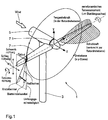
- Fig. 1 shows a perspective view of a wind turbine 1 of the horizontal rotor type with a tower 3, a machine nacelle 5 and two rotor blades 7 a rotor hub 7.1.
- the essential angular and directional relationships are in the figure as well as the force curve of the thrust (perpendicular to the rotor plane) and the tangential force (in the rotor plane) in the longitudinal direction of a rotor blade 7 shown.
- the main vibration loads on the rotor blade result from the swivel moment around the z-axis in the xy-plane and that at so-called "blow" - a pivoting movement out of the xy plane - occurring forces and moments.
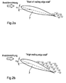
- FIGS. 2a and 2b show a conventional cross-sectional representation 1 at two different angles of attack ⁇ 1 and ⁇ 2 and illustrate the onset of buoyancy-reducing eddies on the trailing edge of the rotor blade ("start of trailing edge stall" - Fig. 2a) or hiking the Swirl zone over the top of the rotor blade in the direction of the leading edge increasing wind speed (“high trailing edge stall" - Fig. 2b).
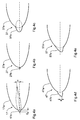
- FIG. 3a and 3b are the dependency of the aerodynamic forces F (in any units) of the angle of attack ⁇ in a conventional (Fig. 3a) or a rotor blade according to the invention (Fig. 3b) graphically represented by Changes in the inflow angle due to the height profile of the wind speed and / or a sloping flow ("wind shear") and / or the tower shadow or tower piling effect and especially as a result of turbulence dynamic load (excessive buoyancy).
- Wind shear a sloping flow
- turbulence dynamic load excessive buoyancy
- the rotor blade passes through the 3a and 3b shown hysteresis loops, whose area is proportional to the vibration excitation energy is that when going through the hysteresis loops in the Rotor blade is introduced. It can be seen that the hysteresis effect by the Measures according to the invention is significantly reduced, specifically the dynamic power increase is significantly lower. The invention Rotor blades therefore experience significantly less vibration excitation.
- 4a to 4e are the respective ones in schematic cross-sectional representations Profile leading edge areas shown differently shaped rotor blades, each an aerodynamically low-resistance molded superimposed on the primary profile Have secondary profile.
- FIG. 4a shows a rotor blade 17 with a secondary profile similar to the primary profile 17a 17b, which projects a distance d beyond the front edge of the primary profile, which is about 3% of its length, and its chord (i.e. the Connecting line between profile front and rear edge) by a small angle ⁇ is inclined with respect to the chord of the primary profile.
- FIG. 4b shows a rotor blade 27, in which on the front edge of the primary profile 27a an approximately circular cross-section vibration damping profile 27b is put on.
- this version can be carried out in a very simple manner Gluing a wire or rod realized on a conventional rotor blade become.
- Fig. 4c shows a rotor blade 37, in which in the front edge of the primary profile 37a is used in cross-section elliptical profile 37b, about half of which Length and about 10% of the length of the primary profile protrudes from this.
- 4d and 4e illustrate rotor blades 47 and 57, in which the primary profile 47a or 57a a secondary airfoil profile 47b provided with a leading edge or 67b is inserted, the leading edge opposite the longitudinal axis of the Primary profile by a distance a of about 10% of the profile thickness Bottom is offset.
- 4e are - in contrast to Profile 47 from Fig. 4d - both transition areas between the primary and the Secondary profile for further aerodynamic optimization and avoidance of Power loss "smoothed" without edges.
- the secondary profile can already be in the primary profile during the manufacture of the Basic shape of the rotor blade can be molded, but it is also a subsequent one Application to rotor blades prefabricated with a known primary profile - for example by a high-strength adhesive bond - possible, which is especially a retrofit Improvement of the vibration behavior of those already in operation Facilities.
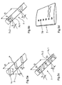
- FIG. 5a to 5e show schematic (not to scale) perspective views Representations of various types of vortex generators suitable for wind turbines as a buoyancy-increasing agent, each in a cutout a rotor blade 7 provided with it.
- the vortex generators in Fig. 5a to 5c the upright on the rotor blade top rectangular Flow deflecting surfaces have the angles of attack relevant to optimization ⁇ , length l, height h, single surface distance in the surface pair or quadruple d or d1 or d2 and generator distance D shown.
- FIGS. 5a to 5c differ mainly in that from each other in Fig. 5a all flow deflecting surfaces 7c.1 the same angle to the leading edge of the sheet, while in Fig. 5b a paired arrangement of surfaces 7c.1, 7c.2 is provided, the surfaces include an angle of + ⁇ or - ⁇ with normal to the leading edge of the sheet, and while in FIG. 5c the surface pairs 7c.1, 7c.2 open alternately towards the front or rear edge of the rotor blade.
- 5d has ramp-like or wedge-shaped elevations 7d the top of the rotor blade 7b. These can shape the top view an isosceles triangle - as shown in the figure - or one right triangle.
- the vortex generators are optionally changed to the Primary and secondary profile formed rotor blade placed, in particular glued.
- the secondary profile is in the radial direction of the sheet a variable cross section.
- the geometry of the Secondary profile in particular to scale the taper of the leaf profile.
- the flow separation in the area of the sheet trailing edge Force effect over a length of the sheet substantially equal to that generated by the flow separation in the area of the profile leading edge Force effect, so that the local torsional moment is balanced.
- the embodiment of the invention is not limited to the above specified preferred embodiments. Rather is a number of Variants possible, which of the solution shown also in a different kind Use execution.
Applications Claiming Priority (2)
| Application Number | Priority Date | Filing Date | Title |
|---|---|---|---|
| DE19815519A DE19815519A1 (de) | 1998-03-31 | 1998-03-31 | Rotorblatt für eine Windkraftanlage |
| DE19815519 | 1998-03-31 |
Publications (2)
| Publication Number | Publication Date |
|---|---|
| EP0947693A2 true EP0947693A2 (de) | 1999-10-06 |
| EP0947693A3 EP0947693A3 (de) | 2001-11-14 |
Family
ID=7863845
Family Applications (1)
| Application Number | Title | Priority Date | Filing Date |
|---|---|---|---|
| EP99104853A Withdrawn EP0947693A3 (de) | 1998-03-31 | 1999-03-11 | Rotorblatt für eine Windkraftanlage |
Country Status (2)
| Country | Link |
|---|---|
| EP (1) | EP0947693A3 (zh) |
| DE (1) | DE19815519A1 (zh) |
Cited By (22)
| Publication number | Priority date | Publication date | Assignee | Title |
|---|---|---|---|---|
| WO2000075508A1 (en) * | 1999-06-07 | 2000-12-14 | Bonus Energy A/S | Method on regulating the air flow around the windmill wing and device for use in such method |
| NL1015558C2 (nl) * | 2000-06-28 | 2002-01-08 | Stichting En Onderzoek Ct Nede | Blad van een windturbine. |
| WO2004029449A1 (de) | 2002-09-21 | 2004-04-08 | Aloys Wobben | Rotorblatt für windturbine |
| WO2007089136A2 (en) * | 2006-02-03 | 2007-08-09 | Pantheon Bv | Wind turbine tower vibration damping |
| WO2008001080A1 (en) * | 2006-06-27 | 2008-01-03 | Derek Alan Taylor | Device for enhancing the effectiveness of power conversion from wind and other fluids |
| EP2017467A1 (en) | 2007-07-20 | 2009-01-21 | Siemens Aktiengesellschaft | Wind turbine rotor blade and pitch regulated wind turbine |
| US8047801B2 (en) | 2010-06-23 | 2011-11-01 | General Electric Company | Wind turbine blades with aerodynamic vortex elements |
| US8061986B2 (en) | 2010-06-11 | 2011-11-22 | General Electric Company | Wind turbine blades with controllable aerodynamic vortex elements |
| US8167554B2 (en) | 2011-01-28 | 2012-05-01 | General Electric Corporation | Actuatable surface features for wind turbine rotor blades |
| DE202012005356U1 (de) | 2012-05-30 | 2012-07-10 | Petra Staude | Rotorblatt für Windturbinen mit Profilen in Tandemanordnung |
| EP2484896A1 (en) * | 2011-02-04 | 2012-08-08 | LM Wind Power A/S | Mounting of vortex generator devices on a wind turbine rotorblade by means of mounting plate |
| WO2014016326A1 (en) * | 2012-07-25 | 2014-01-30 | Lm Wp Patent Holding A/S | Wind turbine blade having a shaped stall fence or flow diverter |
| US8678746B2 (en) | 2006-06-09 | 2014-03-25 | Vestas Wind Systems A/S | Wind turbine blade and a pitch controlled wind turbine |
| US9267491B2 (en) | 2013-07-02 | 2016-02-23 | General Electric Company | Wind turbine rotor blade having a spoiler |
| US9523279B2 (en) | 2013-11-12 | 2016-12-20 | General Electric Company | Rotor blade fence for a wind turbine |
| DK201570884A1 (en) * | 2015-08-19 | 2017-03-06 | Envision Energy (Jiangsu) Co Ltd | Wind turbine blade with tripping device and method thereof |
| US9752559B2 (en) | 2014-01-17 | 2017-09-05 | General Electric Company | Rotatable aerodynamic surface features for wind turbine rotor blades |
| US10087912B2 (en) | 2015-01-30 | 2018-10-02 | General Electric Company | Vortex generator for a rotor blade |
| US10465652B2 (en) | 2017-01-26 | 2019-11-05 | General Electric Company | Vortex generators for wind turbine rotor blades having noise-reducing features |
| US10487796B2 (en) | 2016-10-13 | 2019-11-26 | General Electric Company | Attachment methods for surface features of wind turbine rotor blades |
| CN112639284A (zh) * | 2018-08-30 | 2021-04-09 | 乌本产权有限公司 | 用于风能设备的转子叶片和风能设备 |
| CN112639284B (zh) * | 2018-08-30 | 2024-04-16 | 乌本产权有限公司 | 用于风能设备的转子叶片和风能设备 |
Families Citing this family (6)
| Publication number | Priority date | Publication date | Assignee | Title |
|---|---|---|---|---|
| DE19963086C1 (de) * | 1999-12-24 | 2001-06-28 | Aloys Wobben | Rotorblatt für eine Windenergieanlage |
| DE10202995B4 (de) * | 2002-01-26 | 2004-01-29 | Nordex Energy Gmbh | Rotorblatt für eine Windkraftanlage mit einer Dämpfereinrichtung |
| DE10347802B3 (de) * | 2003-10-10 | 2005-05-19 | Repower Systems Ag | Rotorblatt für eine Windkraftanlage |
| DE102006017897B4 (de) | 2006-04-13 | 2008-03-13 | Repower Systems Ag | Rotorblatt einer Windenergieanlage |
| DE102012007261A1 (de) | 2012-04-12 | 2013-10-17 | Ullrich Meyer | Ring-Windrad |
| DE102016224889B4 (de) * | 2016-12-14 | 2019-11-07 | Airbus Defence and Space GmbH | Verfahren zur Vorbeugung einer Ablösung einer Fluidströmung, Strömungskörpersystem und Luftfahrzeug |
Citations (4)
| Publication number | Priority date | Publication date | Assignee | Title |
|---|---|---|---|---|
| WO1993021327A1 (en) | 1992-04-13 | 1993-10-28 | The Government Of The United States Of America As Represented By The Secretary Of The Department Of Health And Human Services | Immortalized human cell lines containing exogenous cytochrome p450 genes |
| WO1994017303A1 (en) | 1992-11-05 | 1994-08-04 | Bonus Energy A/S | Windmill blade |
| WO1995019500A1 (en) | 1994-01-12 | 1995-07-20 | Lm Glasfiber A/S | Windmill |
| WO1997001709A1 (en) | 1995-06-27 | 1997-01-16 | Bonus Energy A/S | Method and device for reduction of vibrations in a windmill blade |
Family Cites Families (6)
| Publication number | Priority date | Publication date | Assignee | Title |
|---|---|---|---|---|
| US2582118A (en) * | 1946-05-20 | 1952-01-08 | Augustine C Haller | Airplane with movable wing tips |
| US4334658A (en) * | 1979-04-06 | 1982-06-15 | Mackenzie Sprague B | Stalling aerodynamics of the Cessna models 150 and 152 series aircraft |
| US4408958A (en) * | 1980-12-23 | 1983-10-11 | The Bendix Corporation | Wind turbine blade |
| ES2035118T3 (es) * | 1987-03-14 | 1993-04-16 | Mtb Manovriertechnisches Buro | Cuerpo aerodinamico circundado por aire o agua. |
| US5058837A (en) * | 1989-04-07 | 1991-10-22 | Wheeler Gary O | Low drag vortex generators |
| RU2063545C1 (ru) * | 1994-04-22 | 1996-07-10 | Товарищество с ограниченной ответственностью Фирма "Общемаш-Инжиниринг" | Ветродвигатель |
-
1998
- 1998-03-31 DE DE19815519A patent/DE19815519A1/de not_active Withdrawn
-
1999
- 1999-03-11 EP EP99104853A patent/EP0947693A3/de not_active Withdrawn
Patent Citations (4)
| Publication number | Priority date | Publication date | Assignee | Title |
|---|---|---|---|---|
| WO1993021327A1 (en) | 1992-04-13 | 1993-10-28 | The Government Of The United States Of America As Represented By The Secretary Of The Department Of Health And Human Services | Immortalized human cell lines containing exogenous cytochrome p450 genes |
| WO1994017303A1 (en) | 1992-11-05 | 1994-08-04 | Bonus Energy A/S | Windmill blade |
| WO1995019500A1 (en) | 1994-01-12 | 1995-07-20 | Lm Glasfiber A/S | Windmill |
| WO1997001709A1 (en) | 1995-06-27 | 1997-01-16 | Bonus Energy A/S | Method and device for reduction of vibrations in a windmill blade |
Cited By (36)
| Publication number | Priority date | Publication date | Assignee | Title |
|---|---|---|---|---|
| WO2000075508A1 (en) * | 1999-06-07 | 2000-12-14 | Bonus Energy A/S | Method on regulating the air flow around the windmill wing and device for use in such method |
| US6910867B2 (en) | 2000-06-28 | 2005-06-28 | Stichting Energieonderzoek Centrum Nederland | Blade of a wind turbine |
| NL1015558C2 (nl) * | 2000-06-28 | 2002-01-08 | Stichting En Onderzoek Ct Nede | Blad van een windturbine. |
| WO2002008600A1 (en) * | 2000-06-28 | 2002-01-31 | Stichting Energieonderzoek Centrum Nederland | Blade of a wind turbine |
| AU2003266392B2 (en) * | 2002-09-21 | 2007-08-30 | Aloys Wobben | Rotor blade for a wind turbine |
| WO2004029449A1 (de) | 2002-09-21 | 2004-04-08 | Aloys Wobben | Rotorblatt für windturbine |
| US7311490B2 (en) | 2002-09-21 | 2007-12-25 | Aloys Wobben | Rotor blade with an electrical field |
| CN100390407C (zh) * | 2002-09-21 | 2008-05-28 | 艾劳埃斯·乌本 | 风轮机的转子叶片 |
| WO2007089136A2 (en) * | 2006-02-03 | 2007-08-09 | Pantheon Bv | Wind turbine tower vibration damping |
| WO2007089136A3 (en) * | 2006-02-03 | 2007-09-27 | Pantheon Bv | Wind turbine tower vibration damping |
| EP2027390B2 (en) † | 2006-06-09 | 2020-07-01 | Vestas Wind Systems A/S | A wind turbine blade and a pitch controlled wind turbine |
| US8678746B2 (en) | 2006-06-09 | 2014-03-25 | Vestas Wind Systems A/S | Wind turbine blade and a pitch controlled wind turbine |
| WO2008001080A1 (en) * | 2006-06-27 | 2008-01-03 | Derek Alan Taylor | Device for enhancing the effectiveness of power conversion from wind and other fluids |
| US8602739B2 (en) | 2007-07-20 | 2013-12-10 | Siemens Aktiengesellschaft | Wind turbine rotor blade and pitch regulated wind turbine |
| CN101403368B (zh) * | 2007-07-20 | 2012-10-10 | 西门子公司 | 风力涡轮机转子叶片及可调桨距式风力涡轮机 |
| EP2017467A1 (en) | 2007-07-20 | 2009-01-21 | Siemens Aktiengesellschaft | Wind turbine rotor blade and pitch regulated wind turbine |
| US8061986B2 (en) | 2010-06-11 | 2011-11-22 | General Electric Company | Wind turbine blades with controllable aerodynamic vortex elements |
| US8047801B2 (en) | 2010-06-23 | 2011-11-01 | General Electric Company | Wind turbine blades with aerodynamic vortex elements |
| US8167554B2 (en) | 2011-01-28 | 2012-05-01 | General Electric Corporation | Actuatable surface features for wind turbine rotor blades |
| EP2484896A1 (en) * | 2011-02-04 | 2012-08-08 | LM Wind Power A/S | Mounting of vortex generator devices on a wind turbine rotorblade by means of mounting plate |
| US9051919B2 (en) | 2011-02-04 | 2015-06-09 | Lm Windpower A/S | Mounting of vortex generator devices via mounting plate |
| DE202012005356U1 (de) | 2012-05-30 | 2012-07-10 | Petra Staude | Rotorblatt für Windturbinen mit Profilen in Tandemanordnung |
| US9945352B2 (en) | 2012-07-25 | 2018-04-17 | Lm Wp Patent Holding A/S | Wind turbine blade having a shaped stall fence or flow diverter |
| WO2014016326A1 (en) * | 2012-07-25 | 2014-01-30 | Lm Wp Patent Holding A/S | Wind turbine blade having a shaped stall fence or flow diverter |
| CN104662287A (zh) * | 2012-07-25 | 2015-05-27 | Lmwp专利控股有限公司 | 具有成形阻流栅栏或偏流器的风力涡轮机叶片 |
| US9267491B2 (en) | 2013-07-02 | 2016-02-23 | General Electric Company | Wind turbine rotor blade having a spoiler |
| US9523279B2 (en) | 2013-11-12 | 2016-12-20 | General Electric Company | Rotor blade fence for a wind turbine |
| US9752559B2 (en) | 2014-01-17 | 2017-09-05 | General Electric Company | Rotatable aerodynamic surface features for wind turbine rotor blades |
| US10087912B2 (en) | 2015-01-30 | 2018-10-02 | General Electric Company | Vortex generator for a rotor blade |
| DK178874B1 (en) * | 2015-08-19 | 2017-04-18 | Envision Energy (Jiangsu) Co Ltd | Wind turbine blade with tripping device and method thereof |
| DK201570884A1 (en) * | 2015-08-19 | 2017-03-06 | Envision Energy (Jiangsu) Co Ltd | Wind turbine blade with tripping device and method thereof |
| US10487796B2 (en) | 2016-10-13 | 2019-11-26 | General Electric Company | Attachment methods for surface features of wind turbine rotor blades |
| US11274650B2 (en) | 2016-10-13 | 2022-03-15 | General Electric Company | Attachment methods for surface features of wind turbine rotor blades |
| US10465652B2 (en) | 2017-01-26 | 2019-11-05 | General Electric Company | Vortex generators for wind turbine rotor blades having noise-reducing features |
| CN112639284A (zh) * | 2018-08-30 | 2021-04-09 | 乌本产权有限公司 | 用于风能设备的转子叶片和风能设备 |
| CN112639284B (zh) * | 2018-08-30 | 2024-04-16 | 乌本产权有限公司 | 用于风能设备的转子叶片和风能设备 |
Also Published As
| Publication number | Publication date |
|---|---|
| DE19815519A1 (de) | 1999-10-07 |
| EP0947693A3 (de) | 2001-11-14 |
Similar Documents
| Publication | Publication Date | Title |
|---|---|---|
| EP0947693A2 (de) | Rotorblatt für eine Windkraftanlage | |
| DE102006034828B4 (de) | Verfahren und Vorrichtung zur Verringerung von Lasten in einem Rotorblatt | |
| DE102005059298B4 (de) | System und Verfahren zur passiven Lastminderung bei einer Windturbine | |
| EP2217803B1 (de) | Wells-turbine mit passiver rotorblattverstellung | |
| EP3330530B1 (de) | Rotorblatt einer windenergieanlage | |
| WO2007118581A1 (de) | Rotorblatt einer windenergieanlage | |
| EP3408533B1 (de) | Rotorblatt einer windenergieanlage und windenergieanlage | |
| DE2650433B2 (de) | Laufschaufel einer axialen Strömungsmaschine | |
| WO2012164045A1 (de) | Rotor mit einem gekrümmten rotorblatt für eine windkraftanlage | |
| WO2015062710A1 (de) | Rotorblatt einer windenergieanlage und windenergieanlage | |
| EP3399183B1 (de) | Rotorblatt einer windenergieanlage | |
| DE102011122140A1 (de) | Delta-Wirbelstromgeneratoren | |
| DE102008057212A1 (de) | Rotor mit mindestens einem ringförmigen Rotorblatt | |
| EP2976524B1 (de) | Rotorblatt einer windenergieanlage, windenergieanlage und verfahren zum betreiben einer windenergieanlage | |
| WO2020043722A1 (de) | Rotorblatt, windenergieanlage und verfahren zum optimieren einer windenergieanlage | |
| WO2020016351A1 (de) | Rotorblatt für eine windenergieanlage und windenergieanlage | |
| DE60226318T2 (de) | Windturbine mit sekundärrotoren | |
| WO2014090219A2 (de) | Rotorblatt, haltearm und rotor für eine vertikalachswindenergieanlage sowie herstellverfahren und vertikalachswindenergieanlage | |
| EP3981981A1 (de) | Rotorblatt für eine windenergieanlage, windenergieanlage und verfahren zur auslegung eines rotorblatts | |
| WO2020234190A1 (de) | Rotorblatt und windenergieanlage | |
| EP3553306B1 (de) | Windenergieanlagenrotorblatt mit einem vortex-generator | |
| DE102007059285A1 (de) | Rotorblatt für Windenergieanlagen | |
| DE102008051297B3 (de) | Rotorblatt einer Windkraftanlage | |
| WO2016162350A1 (de) | Windenergieanlagen-rotorblatt | |
| DE102017127786A1 (de) | Vertikalwindkraftanlage |
Legal Events
| Date | Code | Title | Description |
|---|---|---|---|
| PUAI | Public reference made under article 153(3) epc to a published international application that has entered the european phase |
Free format text: ORIGINAL CODE: 0009012 |
|
| AK | Designated contracting states |
Kind code of ref document: A2 Designated state(s): AT BE CH CY DE DK ES FI FR GB GR IE IT LI LU MC NL PT SE |
|
| AX | Request for extension of the european patent |
Free format text: AL;LT;LV;MK;RO;SI |
|
| PUAL | Search report despatched |
Free format text: ORIGINAL CODE: 0009013 |
|
| AK | Designated contracting states |
Kind code of ref document: A3 Designated state(s): AT BE CH CY DE DK ES FI FR GB GR IE IT LI LU MC NL PT SE |
|
| AX | Request for extension of the european patent |
Free format text: AL;LT;LV;MK;RO;SI |
|
| RIC1 | Information provided on ipc code assigned before grant |
Free format text: 7F 03D 1/06 A, 7F 03D 11/00 B |
|
| AKX | Designation fees paid | ||
| REG | Reference to a national code |
Ref country code: DE Ref legal event code: 8566 |
|
| RAP1 | Party data changed (applicant data changed or rights of an application transferred) |
Owner name: GENERAL ELECTRIC COMPANY |
|
| STAA | Information on the status of an ep patent application or granted ep patent |
Free format text: STATUS: THE APPLICATION IS DEEMED TO BE WITHDRAWN |
|
| 18D | Application deemed to be withdrawn |
Effective date: 20020515 |