EP0937893A2 - Rotor blade for wind turbine - Google Patents
Rotor blade for wind turbine Download PDFInfo
- Publication number
- EP0937893A2 EP0937893A2 EP99100991A EP99100991A EP0937893A2 EP 0937893 A2 EP0937893 A2 EP 0937893A2 EP 99100991 A EP99100991 A EP 99100991A EP 99100991 A EP99100991 A EP 99100991A EP 0937893 A2 EP0937893 A2 EP 0937893A2
- Authority
- EP
- European Patent Office
- Prior art keywords
- struts
- rotation
- profile
- power plant
- axis
- Prior art date
- Legal status (The legal status is an assumption and is not a legal conclusion. Google has not performed a legal analysis and makes no representation as to the accuracy of the status listed.)
- Withdrawn
Links
- 238000004519 manufacturing process Methods 0.000 description 6
- 238000010276 construction Methods 0.000 description 4
- 239000000969 carrier Substances 0.000 description 3
- 229920001817 Agar Polymers 0.000 description 1
- 238000013016 damping Methods 0.000 description 1
- 238000004870 electrical engineering Methods 0.000 description 1
- 230000005611 electricity Effects 0.000 description 1
- 238000009434 installation Methods 0.000 description 1
- 230000002093 peripheral effect Effects 0.000 description 1
- 238000010248 power generation Methods 0.000 description 1
- 238000005086 pumping Methods 0.000 description 1
- 230000000007 visual effect Effects 0.000 description 1
- XLYOFNOQVPJJNP-UHFFFAOYSA-N water Substances O XLYOFNOQVPJJNP-UHFFFAOYSA-N 0.000 description 1
Images


Classifications
-
- F—MECHANICAL ENGINEERING; LIGHTING; HEATING; WEAPONS; BLASTING
- F03—MACHINES OR ENGINES FOR LIQUIDS; WIND, SPRING, OR WEIGHT MOTORS; PRODUCING MECHANICAL POWER OR A REACTIVE PROPULSIVE THRUST, NOT OTHERWISE PROVIDED FOR
- F03D—WIND MOTORS
- F03D1/00—Wind motors with rotation axis substantially parallel to the air flow entering the rotor
- F03D1/06—Rotors
- F03D1/0608—Rotors characterised by their aerodynamic shape
-
- Y—GENERAL TAGGING OF NEW TECHNOLOGICAL DEVELOPMENTS; GENERAL TAGGING OF CROSS-SECTIONAL TECHNOLOGIES SPANNING OVER SEVERAL SECTIONS OF THE IPC; TECHNICAL SUBJECTS COVERED BY FORMER USPC CROSS-REFERENCE ART COLLECTIONS [XRACs] AND DIGESTS
- Y02—TECHNOLOGIES OR APPLICATIONS FOR MITIGATION OR ADAPTATION AGAINST CLIMATE CHANGE
- Y02E—REDUCTION OF GREENHOUSE GAS [GHG] EMISSIONS, RELATED TO ENERGY GENERATION, TRANSMISSION OR DISTRIBUTION
- Y02E10/00—Energy generation through renewable energy sources
- Y02E10/70—Wind energy
- Y02E10/72—Wind turbines with rotation axis in wind direction
Definitions
- the invention relates to a high-speed wind turbine, with a tower, with one at the top of the tower arranged and about a horizontal axis of rotation rotatable hub and with a maximum of four radially extending from the hub and tangentially spaced air-flowed rotor blades to generate buoyancy and resultant Hub rotation.
- Wind turbines are mainly used for Power generation. However, they are also used for direct drive mechanical, hydraulic or pneumatic devices. The energy is extracted from the air flow by delaying the wind speed.
- the rotor blades are flown by the wind at an angle of attack, whereby an overpressure and a vacuum side on the rotor blades trains so that the necessary lift for the rotation of the hub in the direction of the vacuum side.
- GROWIAN GROß WInd ANlage
- v u peripheral speed at the tip of the blade
- v l wind speed in front of the wind turbine
- the angle of attack between the rotor blades and the wind direction is in a range from 8 ° to 12 °. If the angle of attack is below 8 °, a good flow against the wing is ensured, but the lift generated is not sufficient to operate the system. The maximum lift is reached at an angle of attack of approx. 12 °. Above this value the flow breaks off. The system should therefore ideally be operated at the maximum buoyancy with a constant angle of attack of 12 °. This makes it necessary to provide a complex alignment and control device, for example with the aid of a hydraulic or electromotive adjustment drives.
- the systems can only be operated at higher wind speeds, since the maximum buoyancy at only about 12 ° angle of attack at low wind speeds is not sufficient to turn the things. At high wind speeds, in turn, the systems have to be switched off due to possible fluttering vibrations. All these factors mean that the control effort for the systems is very high, which is reflected in high investment and operating costs.
- a western bike is a typical low-speed wind turbine, at which the fast number lambda significantly below of 4 lies.
- a western bike has one variety of wings that extend radially from the property and arranged tangentially to each other with a small distance are.
- Western bikes are mainly used for pumping water used and found mainly in the United States with about six Millions of units spread widely. From further away they convey the visual impression of a wheel, what to the name "Westernrad” led.
- the individual wings point a geometry that can be produced inexpensively with simple means on.
- the invention has for its object a wind turbine to be provided in a high-speed version, with different Wind conditions can be used without much control effort is.
- this is the case at the beginning of a wind turbine described type achieved in that the rotor blades each an air-flowed lattice profile for generating buoyancy exhibit.
- the rotor blades have a high aerodynamic Effectiveness at angles of attack between 10 ° and 50 °.
- the production of sufficient buoyancy at such high angles of attack is possible because the flow, which is due to the Angle of attack from the negative pressure side of the strut removed, in contact with the flow on the positive pressure side of the next strut comes and from this towards the first Strut is steered back. This will tear off the Flow on the strut flowing through the neighboring strut prevented on the vacuum side.
- the grid profile can be radial with respect to the axis of rotation extending struts and with respect to the axis of rotation have tangentially extending cross struts.
- the Grid profile can also be designed in the form of a segment of a circular arc be.
- the longitudinal struts always serve to generate the Buoyancy.
- the cross struts have the function, the grid profile to reinforce.
- the longitudinal struts can be set at an angle of 30 ° ⁇ 5 ° be arranged opposite the axis of rotation.
- an angle of attack of 30 ° can be selected, since this in the The middle of the possible angle of attack range from 10 ° to 50 °.
- the arrangement of the longitudinal struts at the angle of attack of 30 ° ⁇ 5 ° relative to the axis of rotation can be realized by the longitudinal struts with respect to a surface normal to the main extension plane of the grid profile at the angle of attack of 30 ° ⁇ 5 ° are arranged.
- the angle of attack is preset, so that the lattice profiles with the surface normal of their main extension planes installed parallel to the axis of rotation and can be adjusted, thereby the installation of the lattice profiles is very simple.
- the lattice profile can have struts that face each other in are arranged at an angle of 90 ° so that imaginary diagonals between the connection points of the struts radially and tangentially to the axis of rotation.
- This cross or X construction has the advantage that the struts in both directions Generation of buoyancy can be flown against.
- the surface normals of the main extension plane of the grid profile in the angle of attack of 30 ° ⁇ 5 ° the axis of rotation.
- the grid profile installed around its longitudinal axis rotated by the angle of attack becomes.
- the struts are disregarded of the angle of attack at right angles in the grid profile can be installed. This makes it simple and Cost-effective assembly of the lattice profiles guaranteed.
- the setting the angle of attack occurs later during assembly the rotor blade on the hub.
- the grid profile can be rectangular cross-section with struts have rounded edges. This has the advantage that the Grid profiles and especially the struts a very simple one Have structure so that parts production and assembly can be automated well and are inexpensive to implement.
- the grid profile can have curved struts.
- the arched Struts have the advantage that their profile is a more efficient generation permitted by buoyancy and larger angles of attack possible are.
- the grid profile can have aerodynamically profiled struts.
- these aerodynamically profiled struts have compared to the arched struts the advantage that they are even better are suitable for generating buoyancy and even larger Allow angle of attack.
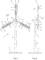
- a wind turbine 1 is shown, the tower 2, which is anchored with its lower end in the bottom 3 is.
- a hub 4 is rotatably arranged that their axis of rotation 5 horizontal and parallel to a wind direction 6 runs.
- radial three carriers 7, which are tangentially spaced and one below the other have an angle of 120 °.
- On the hub 4 opposite end of each carrier 7 is a longitudinal axis 15 rotor blades 8 arranged.
- Each rotor blade 8 has a lattice profile 9 and each of the lattice profiles 9 longitudinal struts 10 and cross struts 11.
- the extend Longitudinal struts are approximately radial, while the transverse struts are tangential run to the axis of rotation 5.
- the grid profile 9 has a main extension plane 12 with a surface normal. The surface normal runs parallel to the axis of rotation 5.
- the Flow which is due to the angle of attack from the negative pressure side the longitudinal strut 10 against which flow flows comes in Contact with the flow on the overpressure side of the next Longitudinal strut 10 and from this in the direction of the first longitudinal strut 10 steered back. In this way the flow will stop on the exposed longitudinal strut 10 through the adjacent longitudinal strut 10 prevents and buoyancy towards the vacuum side generated to a rotation of the hub 4 about the axis of rotation 5 leads according to the direction of rotation 16.
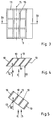
- Fig. 3 is a section of the lattice profile 9 of the upper Rotor wing 8 shown.
- the longitudinal struts 10 are below the angle of attack with respect to the axis of rotation 5 ( Figures 1 and 2) arranged. This can be seen from the fact that in the right Area of the figure, the outer longitudinal strut 10 from the side is observable. In the other longitudinal struts 10 fall Trailing edges of a longitudinal strut 10 with the leading edges of the each arranged to the right of the longitudinal strut 10, so that the rear edges are not visible.
- FIG. 4 shows the section according to IV-IV in FIG. 3. It the angle of attack 14 in relation to the wind direction 6 can be seen, the longitudinal struts 10 with respect to the surface normal 13 the main plane of extent of the lattice profile 9 in the angle of attack 14 are arranged. This means that the longitudinal struts 10 in the grid profile 9 already during manufacture or assembly this angle of attack 14 were used in the lattice profile 9.
- FIG. 5 shows a section corresponding to FIG. 4, where the surface normal 13 of the main extension plane of the Grid profile 9 in the angle of attack 14 with respect to the axis of rotation 5 is arranged. This means that the entire rotor blade with the lattice profile around the longitudinal axis for implementation of the angle of attack 14 has been pivoted. The angle of attack 14 is therefore not already in the manufacture or assembly of the Mesh profiles 9, but only during assembly or adjustment the rotor blade on the hub has been taken into account.
- the wind turbine 1 with the lattice profile 9 is in shown a second embodiment.
- FIG. 7 shows part of the lattice profile rotated about the longitudinal axis 15 9 of the angular power plant 1 according to FIG. 6. The means that the entire rotor blade is rotated by the angle of attack was installed.
- Fig. 8 the angular force system 1 with two arcuate sections Rotor blades 8 shown.
- the run in each case Cross struts 11 between two carriers 7 concentrically around the Rotation axis 5, while the longitudinal struts 10 are radial to the Extend axis of rotation 5. So all buoyancy generating Longitudinal struts 10 the same distance from the axis of rotation 5 on. This has the advantage that all the longitudinal struts 10 have the same relative speed with respect to the hub 4.
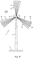
- Fig. 10 the wind turbine 1 with three fan-shaped Rotor blades 8 shown.
- the lattice profiles extend 9 to the hub 4, i.e. they are not carriers intended.
- the cross struts 11 are concentric about the Rotation axis 5 and the longitudinal struts 10 radially to the Rotation axis 5.
- the wind turbine 1 is a continuous rectangular rotor blades 8 shown.
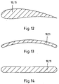
- FIGS. 12 to 14 show possible embodiments of the Struts 10, 11 shown.
- 12 shows aerodynamically profiled struts 10, 11, which are particularly good for generating Buoyancy are suitable.
- the arched struts 10, 11 in FIG. 13 are cheaper to manufacture, but still have good ones aerodynamic properties.
- 14 are struts 10, 11 rectangular cross-section with rounded edges, which is particularly good for use in a lattice profile are suitable because they are sufficiently aerodynamic Properties particularly easy and inexpensive to manufacture are.
Abstract
Description
Die Erfindung betrifft eine Windkraftanlage in Schnelläuferausführung, mit einem Turm, mit einer am oberen Ende des Turms angeordneten und um eine horizontal verlaufende Rotationsachse drehbaren Nabe und mit maximal vier sich von der Nabe radial erstreckenden und tangential beabstandeten luftangeströmten Rotorflügeln zur Erzeugung von Auftrieb und daraus resultierender Drehung der Nabe. Windkraftanlagen dienen hauptsächlich der Stromerzeugung. Sie finden aber auch Anwendung zum direkten An-trieb von mechanischen, hydraulischen oder pneumatischen Vorrichtungen. Der Energieentzug aus der Luftströmung erfogt dabei durch Verzögerung der Windgeschwindigkeit. Die Rotorflügel werden vom Wind unter einem Anstellwinkel angeströmt, wobei sich an den Rotorflügeln eine Überdruck- und eine Unterdruckseite ausbildet, so daß für die Drehung der Nabe erforderlicher Auftrieb in Richtung der Unterdruckseite entsteht. The invention relates to a high-speed wind turbine, with a tower, with one at the top of the tower arranged and about a horizontal axis of rotation rotatable hub and with a maximum of four radially extending from the hub and tangentially spaced air-flowed rotor blades to generate buoyancy and resultant Hub rotation. Wind turbines are mainly used for Power generation. However, they are also used for direct drive mechanical, hydraulic or pneumatic devices. The energy is extracted from the air flow by delaying the wind speed. The rotor blades are flown by the wind at an angle of attack, whereby an overpressure and a vacuum side on the rotor blades trains so that the necessary lift for the rotation of the hub in the direction of the vacuum side.
Eine Windkraftanlage der eingangs beschriebenen Art ist als GROWIAN (GROß WInd ANlage) aus der Zeitschrift Elektrotechnik, Hr. 6 - 1988, Seite 40, "Windenergienutzung - Eine Übersicht" bekannt. Dabei sind meist zwei gegenüberliegende Rotorflügel vorgesehen, die jeweils ein aerodynamisches Profil aufweisen. GROWIANe werden zu den Schnelläufern gezählt, da ihre Schnellaufzahl lambda = vu : vl (vu = Umfangsgeschwindigkeit an der Blattspitze, vl = Windgeschwindigkeit vor dem Windkraftrad) zwischen 4 und 10 liegt. Mit Anlagen dieser Art können Leistungsbeiwerte von 40 bis 45 % erzielt werden. Der theoretische maximale Leistungsbeiwert für Windkraftanlagen liegt bei 59,3 %. Beim Betrieb vom GROWIANen muß gewährleistet werden, daß der Anstellwinkel zwischen den Rotorflügeln und der Windrichtung in einem Bereich von 8° bis 12° liegt. Wenn der Anstellwinkel unterhalb von 8° liegt, ist zwar eine gute Anströmung der Flügel sichergestellt, der erzeugte Auftrieb reicht jedoch nicht für den Betrieb der Anlage aus. Bei ca. 12° Anstellwinkel ist der Maximalauftrieb erreicht. Oberhalb dieses Wertes kommt es zu einem Abreißen der Strömung. Die Anlage sollte somit idealerweise im Auftriebsmaximum bei einem konstant zu haltenden Anstellwinkel von 12° betrieben werden. Dies macht es notwendig, eine aufwendige Ausrichtungs- und Regelungseinrichtung vorzusehen, beispielsweise mit Hilfe einer Hydraulik oder elektromotorischer Verstellantriebe. Die Anlagen können erst bei höheren Windgeschwindigkeiten betrieben werden, da der maximale Auftrieb bei nur ca. 12° Anstellwinkel bei niedrigen Windgeschwindigkeiten nicht zur Drehung der Habe ausreicht. Bei hohen Windgeschwindigkeiten wiederum müssen die Anlagen wegen möglicher Flatterschwingungen abgeschaltet werden. All diese Faktoren führen dazu, daß der Regelungsaufwand für die Anlagen sehr hoch ist, was seinen Niederschlag in hohen Investitionsund Betriebskosten findet.A wind turbine of the type described at the beginning is called GROWIAN (GROß WInd ANlage) from the magazine Elektrotechnik, Hr. 6 - 1988, page 40, "Wind Energy Use - An Overview" known. Usually two opposing rotor blades are provided, each with an aerodynamic profile. GROWIANe are counted among the high-speed runners because their high-speed number lambda = v u : v l (v u = peripheral speed at the tip of the blade, v l = wind speed in front of the wind turbine) is between 4 and 10. With systems of this type, performance coefficients of 40 to 45% can be achieved. The theoretical maximum performance coefficient for wind turbines is 59.3%. When operating the GROWIANen, it must be ensured that the angle of attack between the rotor blades and the wind direction is in a range from 8 ° to 12 °. If the angle of attack is below 8 °, a good flow against the wing is ensured, but the lift generated is not sufficient to operate the system. The maximum lift is reached at an angle of attack of approx. 12 °. Above this value the flow breaks off. The system should therefore ideally be operated at the maximum buoyancy with a constant angle of attack of 12 °. This makes it necessary to provide a complex alignment and control device, for example with the aid of a hydraulic or electromotive adjustment drives. The systems can only be operated at higher wind speeds, since the maximum buoyancy at only about 12 ° angle of attack at low wind speeds is not sufficient to turn the things. At high wind speeds, in turn, the systems have to be switched off due to possible fluttering vibrations. All these factors mean that the control effort for the systems is very high, which is reflected in high investment and operating costs.
Eine weitere Windkraftanlage ist als Westernrad aus der Zeitschrift Elektrotechnik, Nr. 6 - 1988, Seite 39, "Windenergienutzung - Eine Übersicht" bekannt. Bei einem Westernrad handelt es sich um eine Windkraftanlage in typischer Langsamläuferausführung, bei der die Schnellaufzahl lambda deutlich unterhalb von 4 liegt. Ein Westernrad weist eine vielzahl von Flügeln auf, die sich radial von der Habe erstrecken und tangential mit geringem Abstand Zueinander angeordnet sind. Westernräder werden hauptsächlich zum Pumpen von Wasser verwendet und finden vorwiegend in den USA mit ca. sechs Millionen Einheiten eine starke Verbreitung. Von weiterer Entfernung vermitteln sie den optischen Eindruck eines Rads, was zu der Bezeichnung "Westernrad" führte. Die einzelnen Flügel weisen eine mit einfachen Mitteln kostengünstig herzustellende Geometrie auf. Ihre Steuerung wird mit Hilfe einer einfachen Windfahne realisiert, die für eine an die Windrichtung angepaßte Ausrichtung des Westernrads sorgt. Westernräder weisen aufgrund ihrer Geometrie keine besonders hohe Stabilität auf. Wie alle Langsamläufer weisen sie nur einen geringen Wirkungsgrad von etwa 15 % auf, weshalb sich eine Verwendung zur Erzeugung von Strom und dessen Einspeisung ins Netz nicht anbietet.Another wind turbine is from the magazine as a western wheel Electrical Engineering, No. 6 - 1988, page 39, "Use of wind energy - An overview "known. Trades in a western bike it is a typical low-speed wind turbine, at which the fast number lambda significantly below of 4 lies. A western bike has one variety of wings that extend radially from the property and arranged tangentially to each other with a small distance are. Western bikes are mainly used for pumping water used and found mainly in the United States with about six Millions of units spread widely. From further away they convey the visual impression of a wheel, what to the name "Westernrad" led. The individual wings point a geometry that can be produced inexpensively with simple means on. Your control is done with the help of a simple wind vane realized that for a wind direction Alignment of the western wheel ensures. Western bikes show due not particularly high stability due to their geometry. Like all Slow runners have a low efficiency of about 15%, which is why it is used to generate Does not offer electricity and its feeding into the grid.
Der Erfindung liegt die Aufgabe zugrunde, eine Windkraftanlage in Schnelläuferausführung bereitzustellen, die bei unterschiedlichen Windverhältnissen ohne großen Steuerungsaufwand einsetzbar ist.The invention has for its object a wind turbine to be provided in a high-speed version, with different Wind conditions can be used without much control effort is.
Erfindungsgemäß wird dies bei einer Windkraftanlage der eingangs beschriebenen Art dadurch erreicht, daß die Rotorflügel jeweils ein luftdurchströmtes Gitterprofil zur Erzeugung des Auftriebs aufweisen. Die Rotorflügel besitzen eine hohe aerodynamische Wirksamkeit bei Anstellwinkeln zwischen 10° und 50°. Die Erzeugung von ausreichend großem Auftrieb bei derart hohen Anstellwinkeln ist möglich, da die Strömung, die sich aufgrund des Anstellwinkels von der Unterdruckseite der angeströmten Strebe entfernt, in Kontakt mit der Strömung auf der Überdruckseite der nächsten Strebe kommt und von dieser in Richtung der ersten Strebe zurückgelenkt wird. In dieser Weise wird ein Abreißen der Strömung an der angeströmten Strebe durch die benachbarte Strebe auf der Unterdruckseite verhindert. Dadurch ist es möglich, durch Einsatz eines Rotorflügels mit einem Gitterprofil anstelle eines aerodynamisch profilierten Einzelflügels identischer Abmaße den erzeugten Auftrieb auf 300 % und mehr zu erhöhen. Der große Bereich möglicher Anstellwinkel bei einem Gitterprofil von etwa 40° bringt den Vorteil mit sich, daß die Ausrichtung der Rotorflügel relativ zu der Windrichtung nicht exakt eingestellt werden muß. In Gebieten, in denen der Wind vornehmlich aus einer Richtung kommt, ist somit keine Einstellung des Anstellwinkels im Betrieb der Anlage notwendig. Der Einstellwinkel wird lediglich bei der Montage der Anlage gewählt und bleibt dann unverändert. Dies gilt auch für Gebiete, in denen die Abweichung der Windrichtung bei etwa 40° oder darunter liegt, da in diesem Bereich für den Betrieb der Anlage ausreichend Auftrieb erzeugt werden kann. Falls dennoch Einstellbedarf besteht, ist eine sehr einfache Regelung für die Ausrichtung der Rotorflügel gegenüber der Windrichtung ausreichend. Beispielsweise kann hierfür eine einfache und kostengünstige Windfahne verwendet werden. Falls die Anlage im Auftriebsmaximum laufen soll, kann eine bekannte Feinregelung verwendet werden. Die Rotorflügel können in einer leichten Sandwich-Bauweise hergestellt werden, die den Vorteil guter Dämpfungseigenschaften gegenüber Schwingungen mit sich bringt. Bei gleicher Spannweite sind Gitterprofile aufgrund ihrer Geometrie um ein vielfaches leichter und gleichzeitig fester und steifer als aerodynamische Profile. Wegen der geringen Masse, dem daraus resultierenden geringen Losbrechmoment und der hohen aerodynamischen Wirksamkeit kann mit Gitterprofilen schon bei niedrigen Windgeschwindigkeiten Energie gewonnen werden, wodurch eine Anwendung auch in windarmen Gebieten möglich ist. Wegen der hohen Unempfindlichkeit gegen Schwingungen können Gitterpofile aber auch bei hohen Windgeschwindigkeiten, also auch in windstarken Gebieten, eingesetzt werden. Der höhere Strömungswiderstand und der daraus resultierende nominell geringere Wirkungsgrad von Gitterprofilen im Vergleich zu aerodynamischen Profilen wäre beim Einsatz solcher Profile beim Bau von Fluggeräten nachteilig, beim Bau von Windkraftanlagen ist er jedoch unerheblich. Der Widerstand wird Problemlos vom Turm aufgenommen. According to the invention, this is the case at the beginning of a wind turbine described type achieved in that the rotor blades each an air-flowed lattice profile for generating buoyancy exhibit. The rotor blades have a high aerodynamic Effectiveness at angles of attack between 10 ° and 50 °. The production of sufficient buoyancy at such high angles of attack is possible because the flow, which is due to the Angle of attack from the negative pressure side of the strut removed, in contact with the flow on the positive pressure side of the next strut comes and from this towards the first Strut is steered back. This will tear off the Flow on the strut flowing through the neighboring strut prevented on the vacuum side. This makes it possible by using a rotor blade with a grid profile instead of an aerodynamically profiled single wing more identical Dimensions increase the generated buoyancy to 300% and more. Of the large range of possible angles of attack with a grid profile of about 40 ° has the advantage that the orientation of the The rotor blades are not exactly adjusted relative to the wind direction must become. In areas where the wind is primarily from a Direction is not an adjustment of the angle of attack necessary in the operation of the system. The setting angle is only selected when installing the system and then remains unchanged. This also applies to areas in which the deviation of the Wind direction is about 40 ° or below, because in this Sufficient buoyancy is generated in the area for the operation of the system can be. If there is still a need for adjustment, it is very simple regulation for the alignment of the rotor blades opposite the wind direction is sufficient. For example, a simple and inexpensive wind vane can be used. If the system should run at the maximum buoyancy, a known one Fine control can be used. The rotor blades can be in one lightweight sandwich construction can be made, which has the advantage good damping properties against vibrations brings. With the same span, lattice profiles are due their geometry many times lighter and at the same time firmer and stiffer than aerodynamic profiles. Because of the low Mass, the resulting low breakaway torque and The high aerodynamic effectiveness can be achieved with grid profiles energy is generated even at low wind speeds, which means that it can also be used in areas with little wind is. Because of the high insensitivity to vibrations Grid profiles but also at high wind speeds, so can also be used in windy areas. The higher one Flow resistance and the resulting nominal lower efficiency of lattice profiles compared to aerodynamic profiles would be when using such profiles Construction of aircraft disadvantageous in the construction of wind turbines however, it is irrelevant. The resistance is easily from Tower added.
Das Gitterprofil kann sich in Bezug auf die Rotationsachse radial erstreckende Längsstreben und sich in Bezug auf die Rotationsachse tangential erstreckende Querstreben aufweisen. Das Gitterprofil kann auch kreisbogenabschnittförmig ausgebildet sein. Dabei dienen stets die Längsstreben zur Erzeugung des Auftriebs. Die Querstreben haben die Funktion, das Gitterprofil zu verstärken.The grid profile can be radial with respect to the axis of rotation extending struts and with respect to the axis of rotation have tangentially extending cross struts. The Grid profile can also be designed in the form of a segment of a circular arc be. The longitudinal struts always serve to generate the Buoyancy. The cross struts have the function, the grid profile to reinforce.
Die Längsstreben können unter einem Anstellwinkel von 30° ± 5° gegenüber der Rotationsachse angeordnet sein. Vorzugsweise sollte ein Anstellwinkel von 30° gewählt werden, da dieser in der Mitte des möglichen Anstellwinkelbereichs von 10° bis 50° liegt. Ausgehend von einer Windrichtung, die parallel zu der Rotationsachse der Habe verläuft, führt somit eine Abweichung der Windrichtung von ± 20° zu keiner Notwendigkeit der Neuausrichtung der Längsstreben des Gitterprofils oder gar dem Stillstand der Anlage.The longitudinal struts can be set at an angle of 30 ° ± 5 ° be arranged opposite the axis of rotation. Preferably should an angle of attack of 30 ° can be selected, since this in the The middle of the possible angle of attack range from 10 ° to 50 °. Starting from a wind direction that is parallel to the axis of rotation the property runs, thus leads to a deviation in the wind direction of ± 20 ° with no need for realignment the longitudinal struts of the lattice profile or even the standstill of the Investment.
Die Anordung der Längsstreben unter dem Anstellwinkel von 30° ± 5° gegenüber der Rotationsachse kann realisiert werden, indem die Längsstreben gegenüber einer Flächennormalen der Haupterstreckungsebene des Gitterprofils in dem Anstellwinkel von 30° ± 5° angeordnet sind. Dies bedeutet, daß die Längsstreben unter dem Anstellwinkel schräg in dem Gitterprofil angeordnet sind. Hierdurch wird eine Voreinstellung des Anstellwinkels erreicht, so daß die Gitterprofile mit den Flächennormalen ihrer Haupterstreckungsebenen parallel zu der Rotationsachse eingebaut und eingestellt werden können, wodurch der Einbau der Gitterprofile sehr einfach ist.The arrangement of the longitudinal struts at the angle of attack of 30 ° ± 5 ° relative to the axis of rotation can be realized by the longitudinal struts with respect to a surface normal to the main extension plane of the grid profile at the angle of attack of 30 ° ± 5 ° are arranged. This means that the struts below the angle of attack are arranged obliquely in the grid profile. As a result, the angle of attack is preset, so that the lattice profiles with the surface normal of their main extension planes installed parallel to the axis of rotation and can be adjusted, thereby the installation of the lattice profiles is very simple.
Dabei kann das Gitterprofil Streben aufweisen, die zueinander in einem Winkel von 90° so angeordnet sind, daß gedachte Diagonalen zwischen den Verbindungsstellen der Streben radial und tangential zu der Rotationsachse verlaufen. Diese Kreuz- oder X-Bauweise hat den Vorteil, daß die Streben in beiden Richtungen zur Erzeugung von Auftrieb angeströmt werden. The lattice profile can have struts that face each other in are arranged at an angle of 90 ° so that imaginary diagonals between the connection points of the struts radially and tangentially to the axis of rotation. This cross or X construction has the advantage that the struts in both directions Generation of buoyancy can be flown against.
Alternativ können die Flächennormalen der Haupterstreckungsebene des Gitterprofils in dem Anstellwinkel von 30° ± 5° gegenüber der Rotationsachse verlaufen. Dies bedeutet, daß das Gitterprofil um seine Längsachse um den Anstellwinkel verdreht eingebaut wird. Besonders vorteilhaft ist dabei, daß die Streben ohne Berücksichtigung des Anstellwinkels rechtwinklig in das Gitterprofil eingebaut werden können. Dadurch wird eine einfache und kostengünstige Montage der Gitterprofile gewährleistet. Die Einstellung des Anstellwinkels erfolgt erst später bei der Montage der Rotorflügel an der Nabe.Alternatively, the surface normals of the main extension plane of the grid profile in the angle of attack of 30 ° ± 5 ° the axis of rotation. This means that the grid profile installed around its longitudinal axis rotated by the angle of attack becomes. It is particularly advantageous that the struts are disregarded of the angle of attack at right angles in the grid profile can be installed. This makes it simple and Cost-effective assembly of the lattice profiles guaranteed. The setting the angle of attack occurs later during assembly the rotor blade on the hub.
Das Gitterprofil kann Streben rechteckigen Querschnitts mit abgerundeten Kanten aufweisen. Dies hat den Vorteil, daß die Gitterprofile und insbesondere die Streben einen sehr einfachen Aufbau haben, so daß Teilefertigung und Montage gut automatisierbar und kostengünstig zu realisieren sind.The grid profile can be rectangular cross-section with struts have rounded edges. This has the advantage that the Grid profiles and especially the struts a very simple one Have structure so that parts production and assembly can be automated well and are inexpensive to implement.
Das Gitterprofil kann gewölbte Streben aufweisen. Die gewölbten Streben haben den Vorteil, daß ihr Profil eine effizientere Erzeugung von Auftrieb gestattet und größere Anstellwinkel möglich sind.The grid profile can have curved struts. The arched Struts have the advantage that their profile is a more efficient generation permitted by buoyancy and larger angles of attack possible are.
Das Gitterprofil kann aerodynamisch profilierte Streben aufweisen. Diese aerodynamisch profilierten Streben haben wiederum gegenüber den gewölbten Streben den Vorteil, daß sie noch besser zur Erzeugung von Auftrieb geeignet sind und noch größere Anstellwinkel zulassen.The grid profile can have aerodynamically profiled struts. In turn, these aerodynamically profiled struts have compared to the arched struts the advantage that they are even better are suitable for generating buoyancy and even larger Allow angle of attack.
Die Erfindung wird anhand bevorzugter Ausführungsbeispiele weiter beschrieben und erläutert. Dabei zeigt:
- Fig. 1
- eine Vorderansicht einer Windkraftanlage in einer ersten Ausführungsform,
- Fig. 2
- eine Seitenansicht der Windkraftanlage gemäß Figur 1,
- Fig. 3
- eine Detailansicht eines Gitterprofils der Windkraftanlage gemäß Figur 1,
- Fig. 4
- einen Schnitt durch das Gitterprofil der Windkraftanlage gemäß Figur 1 entlang der Linie IV-IV in Fig. 3,
- Fig. 5
eine Figur 4 entsprechende Schnittansicht eines Gitterprofils bei einer alternativen Anordnung von Längsstreben,- Fig. 6
- eine Vorderansicht einer zweiten Ausführungsform der Windkraftanlage,
- Fig. 7
- eine Detailansicht eines Gitterprofils der Windkraftanlage gemäß Figur 6,
- Fig. 8
- eine Vorderansicht der Windkraftanlage in einer dritten Ausführungsform,
- Fig. 9
- eine Detailansicht eines Gitterprofils der Windkraftanlage gemäß Figur 8,
- Fig. 10
- eine Vorderansicht einer weiteren Ausführungsform der Windkraftanlage,
- Fig. 11
- eine Vorderansicht einer weiteren Ausführungsform der Windkraftanlage,
- Fig. 12
- eine Schnittansicht einer aerodynamisch profilierten Strebe eines Gitterprofils,
- Fig. 13
- eine Schnittansicht einer gewölbten Strebe eines Gitterprofils, und
- Fig. 14
- eine Schnittansicht einer Strebe eines Gitterprofils mit rechteckigem Querschnitt und abgerundeten Kanten.
- Fig. 1
- 2 shows a front view of a wind turbine in a first embodiment,
- Fig. 2
- 2 shows a side view of the wind turbine according to FIG. 1,
- Fig. 3
- 2 shows a detailed view of a lattice profile of the wind power plant according to FIG. 1,
- Fig. 4
- 2 shows a section through the lattice profile of the wind turbine according to FIG. 1 along the line IV-IV in FIG. 3,
- Fig. 5
- 4 shows a sectional view corresponding to FIG. 4 of a lattice profile in an alternative arrangement of longitudinal struts,
- Fig. 6
- 2 shows a front view of a second embodiment of the wind turbine,
- Fig. 7
- 6 shows a detailed view of a lattice profile of the wind turbine according to FIG. 6,
- Fig. 8
- a front view of the wind turbine in a third embodiment,
- Fig. 9
- 8 shows a detailed view of a lattice profile of the wind turbine according to FIG. 8,
- Fig. 10
- 2 shows a front view of a further embodiment of the wind power plant,
- Fig. 11
- 2 shows a front view of a further embodiment of the wind power plant,
- Fig. 12
- 1 shows a sectional view of an aerodynamically profiled strut of a lattice profile,
- Fig. 13
- a sectional view of a curved strut of a lattice profile, and
- Fig. 14
- a sectional view of a strut of a lattice profile with a rectangular cross section and rounded edges.
In Fig. 1 ist eine Windkraftanlage 1 dargestellt, die einen Turm
2 aufweist, der mit seinem unteren Ende in dem Boden 3 verankert
ist. Am oberen Ende des Turms 2 ist eine Nabe 4 so drehbar angeordnet,
daß ihre Rotationsachse 5 horizontal und parallel zu
einer Windrichtung 6 verläuft. Von der Nabe 4 erstrecken sich
radial drei Träger 7, die tangential beabstandet sind und untereinander
einen Winkel von 120° aufweisen. An dem der Nabe 4
abgewandten Ende jedes Trägers 7 ist jeweils ein eine Längsachse
15 aufweisender Rotorflügel 8 angeordnet. Jeder Rotorflügel 8
weist ein Gitterprofil 9 und jedes der Gitterprofile 9 Längsstreben
10 und Querstreben 11 auf. Dabei erstrecken sich die
Längsstreben annähernd radial, während die Querstreben tangential
zu der Rotationsachse 5 verlaufen. Das Gitterprofil 9 weist
eine Haupterstreckungsebene 12 mit einer Flächennormalen auf.
Die Flächennormale verläuft parallel zu der Rotationsachse 5.
Bei Betrieb der Windkraftanlage 1 trifft der aus der Windrichtung
6 kommende Wind auf die Längsstreben 10 der Gitterprofile
9, die gegenüber der Windrichtung 6 in einem Anstellwinkel
angestellt sind, so daß an den Längsstreben 10 jeweils eine
Überdruck- und eine Unterdruckseite ausgebildet wird. Die
Strömung, die sich aufgrund des Anstellwinkels von der Unterdruckseite
der angeströmten Längsstrebe 10 entfernt, kommt in
Kontakt mit der Strömung auf der Überdruckseite der nächsten
Längsstrebe 10 und von dieser in Richtung der ersten Längsstrebe
10 zurückgelenkt. In dieser Weise wird ein Abreißen der Strömung
an der angeströmten Längsstrebe 10 durch die benachbarte Längs-strebe
10 verhindert und Auftrieb in Richtung der Unterdruckseite
erzeugt, der zu einer Drehung der Nabe 4 um die Rotationsachse
5 gemäß Drehrichtung 16 führt.In Fig. 1, a
In Fig. 2 ist der obere Rotorflügel 8 in seiner vollen Länge
erkennbar, während die beiden anderen Rotorflügel 8 in der
Blickrichtung hintereinander liegen und nur verkürzt wahrnehmbar
sind. Es ist weiterhin die Flächennormale 13 der Haupterstreckungsrichtung
des Gitterprofils 9 zuerkennen, die parallel
zu der Rotationsachse 5 der Nabe 4 verläuft.In Fig. 2 the
In Fig. 3 ist ein Ausschnitt des Gitterprofils 9 des oberen
Rotorflügels 8 dargestellt. Die Längsstreben 10 sind dabei unter
dem Anstellwinkel gegenüber der Rotationsachse 5 (Figuren 1 und
2) angeordnet. Dies ist dadurch erkennbar, daß im rechten
Bereich der Figur die äußere Längsstrebe 10 von der Seite her
betrachtbar ist. Bei den anderen Längsstreben 10 fallen die
Hinterkanten der einen Längsstrebe 10 mit den Vorderkanten der
jeweils rechts davon angeordneten Längsstrebe 10 zusammen, so
daß die Hinterkanten nicht sichtbar sind.In Fig. 3 is a section of the
In Fig. 4 ist der Schnitt gemäß IV-IV in Fig. 3 dargestellt. Es
ist der Anstellwinkel 14 gegenüber der Windrichtung 6 zu erkennen,
wobei die Längsstreben 10 gegenüber der Flächennormalen 13
der Haupterstreckungsebene des Gitterprofils 9 in dem Anstellwinkel
14 angeordnet sind. Das heißt, daß die Längsstreben 10 in
dem Gitterprofil 9 bereits bei der Fertigung bzw. Montage mit
diesem Anstellwinkel 14 in das Gitterprofil 9 eingesetzt wurden.4 shows the section according to IV-IV in FIG. 3. It
the angle of
In Fig. 5 ist ein Fig. 4 entsprechender Schnitt dargestellt,
wobei hier die Flächennormale 13 der Haupterstreckungsebene des
Gitterprofils 9 in dem Anstellwinkel 14 gegenüber der Rotationsachse
5 angeordnet ist. Dies bedeutet, daß der gesamte Rotorflügel
mit dem Gitterprofil um die Längsachse zur Realisierung
des Anstellwinkels 14 verschwenkt wurde. Der Anstellwinkel 14
ist also nicht bereits bei der Fertigung bzw. Montage der
Gitterprofile 9, sondern erst bei der Montage bzw. Einstellung
der Rotorflügel an der Nabe berücksichtigt worden.5 shows a section corresponding to FIG. 4,
where the surface normal 13 of the main extension plane of the
In Fig. 6 ist die Windkraftanlage 1 mit dem Gitterprofil 9 in
einer zweiten Ausführungsform dargestellt. Bei dieser Ausführungsform
sind die Streben zueinander in einem Winkel von 90°
so angeordnet, daß gedachte Diagonalen zwischen den Verbindungsstellen
der Streben radial und tangential zu der Rotationsachse
5 verlaufen.6, the
In Fig. 7 ist ein Teil des um die Längsachse 15 verdrehten Gitterprofils
9 der Winkraftanlage 1 gemäß Figur 6 dargestellt. Das
heißt, daß der gesamte Rotorflügel um den Anstellwinkel verdreht
eingebaut wurde.7 shows part of the lattice profile rotated about the
In Fig. 8 ist die Winkraftanlage 1 mit zwei kreisbogenabschnittförmigen
Rotorflügeln 8 dargestellt. Dabei verlaufen jeweils die
Querstreben 11 zwischen zwei Trägern 7 konzentrisch um die
Rotationsachse 5, während sich die Längsstreben 10 radial zu der
Rotationsachse 5 erstrecken. Damit weisen alle Auftrieb erzeugenden
Längsstreben 10 den gleichen Abstand zu der Rotations-achse
5 auf. Dies hat den Vorteil, daß alle Längsstreben 10 die
gleiche Relativgeschwindigkeit gegenüber der Nabe 4 aufweisen.In Fig. 8, the
In Fig. 9 ist die angestellte Anordung der Längsstreben 10
besonders gut erkennbar, da in dieser Ansicht, aufgrund des
größeren Abstands zwischen den einzelnen Längsstreben 10, die
Vorderkanten und Hinterkanten der Längsstreben 10 nicht
zusammenfallen.9 shows the arrangement of the
In Fig. 10 ist die Windkraftanlage 1 mit drei fächerförmigen
Rotorflügeln 8 dargestellt. Dabei erstrecken sich die Gitterprofile
9 bis hin zu der Nabe 4, d.h., es sind keine Träger
vorgesehen. Die Querstreben 11 verlaufen konzentrisch um die
Rotationsachse 5 und die Längsstreben 10 radial zu der
Rotationsachse 5.In Fig. 10, the
In Fig. 11 ist die Windkraftanlage 1 mit einem durchgängigen
rechteckigen Rotorflügel 8 dargestellt. In Fig. 11, the
In den Figuren 12 bis 14 sind mögliche Ausführungsformen der
Streben 10, 11 dargestellt. Dabei zeigt Fig. 12 aerodynamisch
profilierte Streben 10, 11, die besonders gut zur Erzeugung von
Auftrieb geeignet sind. Die gewölbten Streben 10, 11 in Fig. 13
sind kostengünstiger herzustellen, weisen aber immer noch gute
aerodynamische Eigenschaften auf. In Fig. 14 sind Streben 10, 11
rechteckigen Querschnitts mit abgerundeten Kanten dargestellt,
die besonders gut für die Anwendung in einem Gitterprofil
geeignet sind, da sie bei ausreichend guten aerodynamischen
Eigenschaften besonders einfach und kostengünstig herstellbar
sind. FIGS. 12 to 14 show possible embodiments of the
- 1 -1 -
- WindkraftanlageWind turbine
- 2 -2 -
- Turmtower
- 3 -3 -
- Bodenground
- 4 -4 -
- Nabehub
- 5 -5 -
- RotationsachseAxis of rotation
- 6 -6 -
- WindrichtungWind direction
- 7 -7 -
- Trägercarrier
- 8 -8th -
- RotorflügelRotor blades
- 9 -9 -
- GitterprofilGrid profile
- 10 -10 -
- LängsstrebeLongitudinal strut
- 11 -11 -
- QuerstrebeCross strut
- 12 -12 -
- HaupterstreckungsebeneMain extension level
- 13 -13 -
- FlächennormaleSurface normal
- 14 -14 -
- AnstellwinkelAngle of attack
- 15 -15 -
- LängsachseLongitudinal axis
- 16 -16 -
- DrehrichtungDirection of rotation
Claims (10)
Applications Claiming Priority (2)
| Application Number | Priority Date | Filing Date | Title |
|---|---|---|---|
| DE19807193A DE19807193C1 (en) | 1998-02-20 | 1998-02-20 | Wind-powered energy generation plant |
| DE19807193 | 1998-02-20 |
Publications (2)
| Publication Number | Publication Date |
|---|---|
| EP0937893A2 true EP0937893A2 (en) | 1999-08-25 |
| EP0937893A3 EP0937893A3 (en) | 2001-10-04 |
Family
ID=7858425
Family Applications (1)
| Application Number | Title | Priority Date | Filing Date |
|---|---|---|---|
| EP99100991A Withdrawn EP0937893A3 (en) | 1998-02-20 | 1999-01-21 | Rotor blade for wind turbine |
Country Status (2)
| Country | Link |
|---|---|
| EP (1) | EP0937893A3 (en) |
| DE (1) | DE19807193C1 (en) |
Cited By (2)
| Publication number | Priority date | Publication date | Assignee | Title |
|---|---|---|---|---|
| DE102004053498A1 (en) * | 2004-10-28 | 2006-05-04 | Baumann, Karl, Dr. | Rotor blade for wind mill, has two airfoil flanks fixed at ribs and are connected to aerodynamically profiled molded padding, and vanes placed between ribbed flat segment and flanks, where blade is made of metal sheets and direct material |
| ES2263389A1 (en) * | 2005-06-03 | 2006-12-01 | Esdras Automaticas, S.L. | Sub-blade structure for reducing blade weight in wind turbines |
Families Citing this family (1)
| Publication number | Priority date | Publication date | Assignee | Title |
|---|---|---|---|---|
| SK892007A3 (en) * | 2007-06-26 | 2009-01-07 | Alexander Kaliský | Sequential wing |
Family Cites Families (7)
| Publication number | Priority date | Publication date | Assignee | Title |
|---|---|---|---|---|
| NL24753C (en) * | ||||
| FR636615A (en) * | 1927-06-27 | 1928-04-13 | ||
| US4081221A (en) * | 1976-12-17 | 1978-03-28 | United Technologies Corporation | Tripod bladed wind turbine |
| DE2909781A1 (en) * | 1979-03-13 | 1980-09-25 | Karlheinz Ohlberg | Wind driven power generating turbine - has independent concentric rotors driving common generator to give higher efficiency |
| FR2575790A3 (en) * | 1985-01-08 | 1986-07-11 | Tournier Pierre | Wind machine wheel |
| DE3715265A1 (en) * | 1987-05-08 | 1988-11-24 | Imris Pavel | Wind turbine |
| DE8803598U1 (en) * | 1988-03-17 | 1989-04-20 | Seel, Gerd, 7519 Walzbachtal, De |
-
1998
- 1998-02-20 DE DE19807193A patent/DE19807193C1/en not_active Expired - Fee Related
-
1999
- 1999-01-21 EP EP99100991A patent/EP0937893A3/en not_active Withdrawn
Non-Patent Citations (1)
| Title |
|---|
| ELEKTROTECHNIK: "Windenergienutzung-Eine übersich", vol. 6, 1988, pages: 40 |
Cited By (3)
| Publication number | Priority date | Publication date | Assignee | Title |
|---|---|---|---|---|
| DE102004053498A1 (en) * | 2004-10-28 | 2006-05-04 | Baumann, Karl, Dr. | Rotor blade for wind mill, has two airfoil flanks fixed at ribs and are connected to aerodynamically profiled molded padding, and vanes placed between ribbed flat segment and flanks, where blade is made of metal sheets and direct material |
| ES2263389A1 (en) * | 2005-06-03 | 2006-12-01 | Esdras Automaticas, S.L. | Sub-blade structure for reducing blade weight in wind turbines |
| WO2006128940A1 (en) * | 2005-06-03 | 2006-12-07 | Esdras Automatica, S.L. | Sub-blade structure for reducing blade weight in wind turbines |
Also Published As
| Publication number | Publication date |
|---|---|
| EP0937893A3 (en) | 2001-10-04 |
| DE19807193C1 (en) | 1999-05-27 |
Similar Documents
| Publication | Publication Date | Title |
|---|---|---|
| EP1514023B1 (en) | Wind power plant | |
| EP2273101B1 (en) | Assembly process for rotorblades of a wind turbine | |
| EP0364020B1 (en) | Rotor for a wind motor | |
| EP2469078B1 (en) | Wind energy hybrid rotor | |
| EP2280163B1 (en) | Wind power plant and rotor blade for a wind power plant | |
| EP1002949A2 (en) | Vertical axis wind turbine | |
| WO2012164045A1 (en) | Rotor with a curved rotor blade for a wind power plant | |
| EP1244872A1 (en) | Rotor blade for a wind power installation | |
| AT505351B1 (en) | windmill | |
| DE102008044807A1 (en) | Flow-stream converter, especially a domestic wind-power converter, has two intermediately arranged blades coupled to output shaft | |
| DE19807193C1 (en) | Wind-powered energy generation plant | |
| DE4030559C2 (en) | ||
| EP1387954B1 (en) | Wind turbine comprising a vertical axis | |
| EP3844384A1 (en) | Rotor blade, wind turbine, and method for optimising a wind turbine | |
| DE3505489A1 (en) | Vane for a wind power installation | |
| DE112017004377B4 (en) | wind turbine plant | |
| DE102012107250B4 (en) | Rotor of a vertical axis wind turbine | |
| DE202008005724U1 (en) | Axial flowed through wind turbine | |
| CH700422B1 (en) | Axial-flow wind turbine used for electricity generation, has helical blade with aerodynamic cross section inclined rearwardly toward rotation axis over length of blade | |
| EP2636892A2 (en) | Wind power plant and method for generating of rotary energy from wind | |
| EP3969741B1 (en) | Rotor blade and wind turbine | |
| DE102011017373A1 (en) | Wind turbine | |
| DE102008054126A1 (en) | Rotor for use in wind-power plant, has body comprising upper covering area, middle area and lower covering area that are identically constructed, where middle area exhibits vanes that are limited by spherical surface of ball with radius | |
| WO2021004853A1 (en) | Rotor blade for a wind turbine and wind turbine | |
| DE102013217426B3 (en) | Horizontal rotor turbine with reduced normalized passage speed |
Legal Events
| Date | Code | Title | Description |
|---|---|---|---|
| PUAI | Public reference made under article 153(3) epc to a published international application that has entered the european phase |
Free format text: ORIGINAL CODE: 0009012 |
|
| AK | Designated contracting states |
Kind code of ref document: A2 Designated state(s): AT BE CH CY DE DK ES FI FR GB GR IE IT LI LU MC NL PT SE Kind code of ref document: A2 Designated state(s): GB NL |
|
| AX | Request for extension of the european patent |
Free format text: AL;LT;LV;MK;RO;SI |
|
| RIN1 | Information on inventor provided before grant (corrected) |
Inventor name: WEDEMEYER, ERICH, DR. RER. NAT. Inventor name: HEDDERGOTT, ALFRED, DIPL.-ING. Inventor name: PSOLLA-BRESS, HARTMUT, DIPL.-ING. |
|
| PUAL | Search report despatched |
Free format text: ORIGINAL CODE: 0009013 |
|
| AK | Designated contracting states |
Kind code of ref document: A3 Designated state(s): AT BE CH CY DE DK ES FI FR GB GR IE IT LI LU MC NL PT SE |
|
| AX | Request for extension of the european patent |
Free format text: AL;LT;LV;MK;RO;SI |
|
| 17P | Request for examination filed |
Effective date: 20020130 |
|
| AKX | Designation fees paid |
Free format text: GB NL |
|
| REG | Reference to a national code |
Ref country code: DE Ref legal event code: 8566 |
|
| RAP1 | Party data changed (applicant data changed or rights of an application transferred) |
Owner name: DEUTSCHES ZENTRUM FUER LUFT- UND RAUMFAHRT E.V. |
|
| STAA | Information on the status of an ep patent application or granted ep patent |
Free format text: STATUS: THE APPLICATION IS DEEMED TO BE WITHDRAWN |
|
| 18D | Application deemed to be withdrawn |
Effective date: 20080801 |