EP0845580A2 - Dispositif pour accroitre la transmission de chaleur - Google Patents
Dispositif pour accroitre la transmission de chaleur Download PDFInfo
- Publication number
- EP0845580A2 EP0845580A2 EP98100858A EP98100858A EP0845580A2 EP 0845580 A2 EP0845580 A2 EP 0845580A2 EP 98100858 A EP98100858 A EP 98100858A EP 98100858 A EP98100858 A EP 98100858A EP 0845580 A2 EP0845580 A2 EP 0845580A2
- Authority
- EP
- European Patent Office
- Prior art keywords
- heat transfer
- ribs
- cooling medium
- cooling
- notches
- Prior art date
- Legal status (The legal status is an assumption and is not a legal conclusion. Google has not performed a legal analysis and makes no representation as to the accuracy of the status listed.)
- Granted
Links
Images


Classifications
-
- F—MECHANICAL ENGINEERING; LIGHTING; HEATING; WEAPONS; BLASTING
- F01—MACHINES OR ENGINES IN GENERAL; ENGINE PLANTS IN GENERAL; STEAM ENGINES
- F01D—NON-POSITIVE DISPLACEMENT MACHINES OR ENGINES, e.g. STEAM TURBINES
- F01D5/00—Blades; Blade-carrying members; Heating, heat-insulating, cooling or antivibration means on the blades or the members
- F01D5/12—Blades
- F01D5/14—Form or construction
- F01D5/18—Hollow blades, i.e. blades with cooling or heating channels or cavities; Heating, heat-insulating or cooling means on blades
- F01D5/187—Convection cooling
-
- F—MECHANICAL ENGINEERING; LIGHTING; HEATING; WEAPONS; BLASTING
- F28—HEAT EXCHANGE IN GENERAL
- F28F—DETAILS OF HEAT-EXCHANGE AND HEAT-TRANSFER APPARATUS, OF GENERAL APPLICATION
- F28F3/00—Plate-like or laminated elements; Assemblies of plate-like or laminated elements
- F28F3/02—Elements or assemblies thereof with means for increasing heat-transfer area, e.g. with fins, with recesses, with corrugations
-
- F—MECHANICAL ENGINEERING; LIGHTING; HEATING; WEAPONS; BLASTING
- F05—INDEXING SCHEMES RELATING TO ENGINES OR PUMPS IN VARIOUS SUBCLASSES OF CLASSES F01-F04
- F05D—INDEXING SCHEME FOR ASPECTS RELATING TO NON-POSITIVE-DISPLACEMENT MACHINES OR ENGINES, GAS-TURBINES OR JET-PROPULSION PLANTS
- F05D2240/00—Components
- F05D2240/10—Stators
- F05D2240/12—Fluid guiding means, e.g. vanes
- F05D2240/127—Vortex generators, turbulators, or the like, for mixing
-
- F—MECHANICAL ENGINEERING; LIGHTING; HEATING; WEAPONS; BLASTING
- F05—INDEXING SCHEMES RELATING TO ENGINES OR PUMPS IN VARIOUS SUBCLASSES OF CLASSES F01-F04
- F05D—INDEXING SCHEME FOR ASPECTS RELATING TO NON-POSITIVE-DISPLACEMENT MACHINES OR ENGINES, GAS-TURBINES OR JET-PROPULSION PLANTS
- F05D2260/00—Function
- F05D2260/20—Heat transfer, e.g. cooling
- F05D2260/221—Improvement of heat transfer
- F05D2260/2212—Improvement of heat transfer by creating turbulence
-
- Y—GENERAL TAGGING OF NEW TECHNOLOGICAL DEVELOPMENTS; GENERAL TAGGING OF CROSS-SECTIONAL TECHNOLOGIES SPANNING OVER SEVERAL SECTIONS OF THE IPC; TECHNICAL SUBJECTS COVERED BY FORMER USPC CROSS-REFERENCE ART COLLECTIONS [XRACs] AND DIGESTS
- Y02—TECHNOLOGIES OR APPLICATIONS FOR MITIGATION OR ADAPTATION AGAINST CLIMATE CHANGE
- Y02T—CLIMATE CHANGE MITIGATION TECHNOLOGIES RELATED TO TRANSPORTATION
- Y02T50/00—Aeronautics or air transport
- Y02T50/60—Efficient propulsion technologies, e.g. for aircraft
Definitions
- the present invention relates to a heat transfer promoting structure for promoting the heat transfer between a heat transfer surface and a cooling medium.
- Such structure can be used for example to improve the cooling efficiency of turbine blades of a gas turbine.
- gas turbines There are various types of gas turbines, and one of them is of a direct driving type which is driven by a combustion gas flow and drives a compressor.
- the upper temperature of the main gas flow is limited by the heat resistance of the turbine blade.
- turbine blade which withstands a higher temperature is required.
- the heat resistance of the turbine blades is enhanced by improving the material of the turbine blade and cooling the turbine blades from its inside to lower its surface temperature.
- the turbine blade of this type is formed therein with cooling flow passages for conducting water or a cooling gas such as water vapor or air and uses various means for increasing cooling efficiency.
- One of means for effectively cooling the wall of the cooling flow passage (i.e., the wall portion of an aerofoil blade portion) by the flow of the cooling gas in the cooling flow passage comprises a great number of projections formed in the inner surface of the wall of the cooling flow passage so that the cooling gas flows in a turbulent flow state in the vicinity of the inner surface of the wall.
- FIGS. 20 and 21 An embodiment of a turbine blade having such projections is shown in FIGS. 20 and 21.
- the turbine blade 21 has a shank portion 21a and an aerofoil blade portion 21b.
- the aerofoil blade portion 21b are formed a plurality of cooling flow passages 22 having their ends serially connected together by means of return portions 24.
- a cooling gas supplied from a cooling gas inlet 23 flows through the adjacently arranged cooling flow passages 22 via the return portions 24 and is finally discharged from a nozzle formed in a trailing edge portion 26 into the main gas.
- the inner surface of the suction side walls of the aerofoil blade portion are formed a plurality of turbulence promoting ribs 27 which extend perpendicularly to the flow direction of the cooling gas.
- the cooling gas is formed into a strong turbulence in the vicinity of the inner surface of the wall by means of the turbulence promoting ribs 27.
- the heat transmission through the inner surface is enhanced to improve the cooling effect.
- Partition walls 28 are intended to divide adjacent cooling flow passages 22, and pin fins 29 are formed in the trailing edge portion.
- Jpn. Pat. KOKAI Publication No. 60-101202 discloses a blade having turbulence promoting ribs formed slant-wise with respect to the flowing direction of the cooling gas. Such turbulence promoting ribs produce a strong turbulence to improve the cooling effect. The inclined turbulence promoting ribs can prevent foreign matters from being deposited on or at a specific portion.
- Jpn. Pat. KOKAI Publication No. 5-10101 discloses an arrangement of V-shaped slantwise turbulence promoting ribs.
- the turbulence caused by the turbulence promoting ribs of this prior art is based on the generation of vortexes called "back step flow" at the rear end of the ribs in a direction which crosses a flow direction.
- This vortex extends in a lateral direction, i.e. a direction which crosses a flow direction of the cooling medium.
- a flow which is in an opposite direction to the flow direction is generated around a heat transfer surface.
- the "back step flow” generates over a region several times longer than the height of the turbulence promoting rib.
- a heat transfer promoting structure for promoting heat transfer between a heat transfer surface and a cooling medium which flows along the heat transfer surface in a predetermined direction, comprising a plurality of turbulence promoter elements provided in the flow of the cooling medium for producing turbulence in the flow of the cooling medium, wherein said turbulence promoter elements comprise longitudinal vortex producing elements which are adapted to produce longitudinal vortexes in the flow of the cooling medium.
- this heat transfer promoting said longitudinal vortex producing elements are either formed by projections and/or by notches having an edge inclined with respect to the predetermined flow direction of the cooling medium. Further preferred embodiments are defined in the sub-claims.
- each turbulence promoter inclines to the flow of the cooling medium.
- a longitudinal vortex is therefore generated at the projection or the notch, deflecting the flow of the cooling medium such that the medium collides against the inner surface of a cooling flow passage or a heat transfer surface.
- This increases the cooling efficiency.
- the turbulence promoters produces longitudinal vortexes similar to those generated by the above-mentioned Coriolis force. Since the longitudinal vortexes produced by the turbulence promoters do not interfere with one another, they do not adversely influence the cooling efficiency.
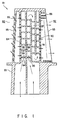
- FIG. 1 is a longitudinal cross-sectional view of a cooled turbine blade and FIG. 2 is an enlarged perspective view of a turbulent promoter according to the first embodiment used in the turbine blade.
- cooling flow passages 84 extending in the span direction so as to perform impingement cooling.
- shower heads 86 for performing film cooling.
- a return flow passage 87 and pin fins 88 perform enforced convection cooling in the range of the blade from the intermediate portion to the trailing edge.
- the cooling medium flows through a cooling flow passage 89 and then passes through the return flow passage 87 formed parallel therewith at the trailing edge side.
- the cooling medium passes through orifices 91 formed in the wall surface of the final flow passage 90 and flows into a trailing portion 92 formed with the pin fins 88.
- the cooling medium flowing into the trailing portion 92 performs convention cooling at the pin fins 88 and then is discharged from the trailing edge 93.
- Projecting ribs 94 and 95 of turbulence promoters as cooling members are provided on the inner wall surfaces of the cooling flow passage 84 in the leading portion 82, the return flow passage 87 and the cooling flow passage 89 in the range of the blade from the intermediate portion to the trailing edge and the final flow passage 90.
- the projecting ribs 94 and 95 are perpendicular to the flow direction X of the cooling medium and separated from each other at predetermined intervals in the flow direction X.
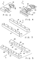
- Each rib has a rectangular shape extending in the flow direction X and triangular notches 96 cut in from the downstream side are formed in the rear portion of the rib.
- the cooling medium is first separated from the ribs 94 and 95 at their front edges. Then, the cooling medium separated from the upper edges of the notches 96 formed in the rear portions of the ribs forms longitudinal vortexes and is discharged. The separated flow of the cooling medium from the front edges of the ribs and the longitudinal vortexes interfere with each other to produce strong turbulence of the cooling medium. As a result, the heat transmitting ratio in the cooling flow passages 84 and 89 and the passages 87 and 90 is improved, and the inner wall surfaces on which the ribs 94 and 95 are provided are cooled efficiently.
- the ribs 94 and 95 are provided in such a way that the notches 96 of the adjacent ribs 94 are arranged in a staggered fashion. This arrangement causes the longitudinal vortexes produced at the upper edges of the notches 96 to be dispersed and discharged in the width direction. This can enhance the heat transmitting ratio over the substantial whole region of the interior of the cooling flow passages 84 and 89 and the flow passages 87 and 90, and the inner wall surfaces on which the ribs 94 and 95 are provided are cooled efficiently.
- one or two notches 96 are formed in each rib 94, 95.
- the number of the notches 96 and their shape are not limited to the ones of this embodiment.
- the notches 96 are formed at the downstream side of the main flow of the cooling medium in this embodiment, but may be formed at the upstream side because longitudinal vortexes are produced in both cases.
- FIG. 3 is a perspective view.
- ribs 97 of turbulence promoters as cooling members has a trapezoidal form extending in the flow direction X of the cooling medium.
- triangular notches 98 are cut in the upstream side of the rib and are arranged at predetermined intervals in the flow direction X.
- the notches 98 are arranged so that their upper edges are inclined at an angle of attack with respect to the flow of the cooling medium and many vortexes are produced at the edges of the notches 98.
- notches 98 provide a strong convection cooling effect, and a cooled member (not shown) provided with the ribs 97, such as a cooled turbine blade formed with flow passages of the cooling medium, can be cooled efficiently.
- the notches 98 are arranged in a staggered fashion along the flow direction X of the cooling medium when a plurality of ribs 97 are provided in the cooled member. This arrangement performs cooling more effectively.
- the ribs 97 are not always required to have the same height as viewed from the flow direction X as shown in FIG. 3.
- the size and the shape of the notches 98 are not always limited to the ones as shown in FIG. 3.
- FIG. 4 is its perspective view and FIG. 5 is a perspective view showing arrangement of a modification.
- each rib 99 of a turbulence promoter as a cooling member has a rectangular shape extending in the flow direction X of the cooling medium and has two triangular notches 100 formed at the downstream side similarly to the rib of the first embodiment.
- the rib 99 has both end surfaces 101 inclined at a predetermined angle with respect to the flow direction X of the cooling medium.
- gaps 104 defined between the end surfaces 101 and flow passage walls 103 are made narrower at the downstream side.
- the flow of the cooling medium separated from the upper edge of each notch 100 forms longitudinal vortexes and is discharged.
- the separated flow from the front edges of the ribs and the longitudinal vortexes interfere with each other to produce strong turbulence of the cooling medium. Since not only further longitudinal vortexes are produced at both end surfaces 101 but also the cooling medium is accelerated, the convection cooling effect in the flow passage 102 of the cooling medium can be further enhanced thereby cooling the cooled turbine blade efficiently.
- rows of the ribs crossing the flow passage 102 are arranged at predetermined intervals in the flow direction X.
- Some rows of the ribs each comprise ribs 105 each having three triangular notches 100 similar to those of the rib 99, and the other rows of ribs 106 have no notches. Both rows of notches are arranged alternately.
- the surfaces of both end portions 101 of the ribs 105 and 106 are inclined at a predetermined angle with respect to the flow direction X of the cooling medium and the downstream side of each rib is narrower than its upstream side.
- a gap 107 between the ribs 105 and 106 is formed narrower in the flow direction X of the cooling medium.
- production of the longitudinal vortexes at both end surfaces 101 of the ribs 105 and 106 acceleration of the cooling medium passing through the gap 107 between the ribs 105 and 106 cooperate to perform effective convection cooling, and the cooled member such as a cooled turbine blade, which forms the flow passage 102, can be cooled efficiently.
- the staggered arrangement of the notches 100 in the flow direction X of the cooling medium allows for effective convection cooling.
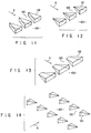
- FIG. 6 is a perspective view.
- a rib 108 of a turbulence promoter as a cooling member has a rectangular shape extending in the flow direction X of the cooling medium, and saw-toothed notches 109 are formed from the rear portion of the rib 108.
- the notches 109 When the notches 109 are disposed in a flow passage 102 through which the cooling medium flows, many longitudinal vortexes are formed at the edges of the notches 109 in the same way as the ribs of the first embodiment and strong turbulence of the cooling medium is produced. In consequence, the heat transmitting rate can be improved.
- the notches 109 can be formed in the upstream end portion of the rib 108 and the cut-in angle of the notches 108 and their size are not limited to the ones as shown in FIG. 6.
- FIG. 7 is a perspective view.
- a rib 110 of a turbulence promoter as a cooling member has a rectangular shape extending in the flow direction X of the cooling medium, and triangular notches 111 are formed from the rear portion of the rib.
- the ribs 110 When the ribs 110 are provided in a flow passage 102, many longitudinal vortexes are produced at edges of the notches 111 and strong turbulence of the cooling medium is generated similarly to the ribs of the fourth embodiment. In this regard, this embodiment provides the similar effect to that of the fourth embodiment.
- the notches 111 may be formed in the upstream portion of the rib 110, and the number of the notches 111 and their size are not limited to the ones as shown in FIG. 7.
- FIG. 8 is a perspective view.
- a rib 112 of a turbulence promoter as a cooling member has a rectangular shape extending in the flow direction X of the cooling medium, and trapezoidal notches 113 are formed from the rear portion of the rib.
- the ribs 112 When the ribs 112 are provided in a flow passage 102, many longitudinal vortexes are produced at edges of the notches 113 and strong turbulence of the cooling medium is generated similarly to the ribs of the seventh embodiment. In this regard, this embodiment provides the similar effect to that of the fourth embodiment.
- the notches 113 may be formed in the upstream portion of the rib 112, and the number of the notches 113 and their size are not limited to the ones as shown in FIG. 8.
- FIG. 9 is a perspective view.
- a rib 114 of a turbulence promoter as a cooling member has a triangular cross section extending in the flow direction X of the cooling medium, and triangular notches 115 are formed from the rear portion of the rib.
- the notches 115 prevent formation of a stagnant area in front of the ribs, whereby pressure loss of the cooling medium can be reduced.
- the notches 115 may be formed in the upstream side of each rib, and the number and the size of the notches 115 are not always limited to the ones as shown in FIG. 9.
- each of ribs 116 of a turbulence promoter as a cooling member has a triangular cross section extending in the flow direction X of the cooling medium, and triangular notches 117 and 118 having different sizes are formed from the rear portion of the rib 106.
- the notches 117 and 118 have different cut-in depths, the heights of edges of the notches at which longitudinal vortexes are produced can be changed. Thus, strong turbulence can be produced by longitudinal vortexes generated at both different widths and different heights, and the convection cooling effect is enhanced.
- the notches 117 and 118 may be formed in the upstream side of each rib, and the number and the size of the notches are not always limited to the ones as shown in FIG. 10.
- each of ribs 119 of a turbulence promoter as a cooling member has a triangular prism shape.
- the ribs 119 are arranged in a flow passage 102 with gaps 120 provided between the adjacent ribs 119 and with the apexes thereof directed toward the downward side.
- the cooling medium is separated from the edges of the ribs 119 and forms many longitudinal vortexes in the cooling medium whereby strong turbulence is produced in the cooling medium. In this way, the heat transmission rate can be enhanced in the flow passage 102.
- the cooling medium passing through the gaps between the ribs 119 is accelerated to perform effective convection cooling.
- a stagnant area in front of the ribs 119 is decreased.
- pressure loss of the cooling medium is reduced.
- a stagnant portion in the flow passage 102 is also reduced. Therefore, accumulation of dust around the ribs 119 can be suppressed and lowering of the cooling capacity of the member can be prevented.
- the triangular prism shaped ribs 119 are arranged in a row. However, it is more preferable that ribs 119 be arranged in a staggered fashion with respect to the flow direction of the cooling medium.
- the size and the shape of the ribs 119 are not always limited to the ones as shown in FIG. 11. The ribs having different sizes can be used instead.
- FIG. 12 is a perspective view.
- each of ribs 121 of a turbulence promoter as a cooling member has a triangular wedge shape.
- the ribs 121 are arranged with their apexes directed toward the upstream side so that gaps 120 are formed between the adjacent ribs 121 in the flow passage 102 through which the cooling medium flows.
- This structure provides the similar effect to that of the ninth embodiment.
- FIG. 13 is a perspective view.
- each of ribs 122 of a turbulence promoter as a cooling member has a rectangular wedge shape.
- the ribs 122 are arranged with their apexes directed toward the upstream side so that gaps 120 are formed between the adjacent ribs 122 in the flow passage 102 through which the cooling medium flows.
- This structure provides the similar effect to that of the ninth embodiment.
- each of ribs 123 of a turbulence promoter as a cooling member has a tetrahedral wedge shape.
- the ribs 123 are arranged with their apexes directed toward the upstream side so that gaps 120 are formed between the adjacent rows of ribs 123.
- This structure provides the similar effect to that of the ninth embodiment.
- the ribs 123 are arranged in a staggered fashion with a predetermined space left in the flow direction X of the cooling medium so as to perform effective convection cooling.
- each of ribs 124 of a turbulence promoter as a cooling member has a triangular wedge shape.
- the ribs 124 are arranged with their apexes directed toward the upstream side so that gaps 120 are formed between the adjacent ribs 124.
- a triangular prism shaped notch 125 is formed in the rear portion of the rib 124. This structure provides the similar effect to that of the ninth embodiment. In place of triangular wedge shaped ribs 124, the ribs of the ninth to eleventh embodiments can be used.
- FIG. 16 is a perspective view.
- a rib 126 of a turbulence promoter as a cooling member has a streamlined cross section extending in the flow direction X of the cooling medium.
- FIG. 17 is a perspective view.
- a rib 127 of a turbulence promoter as a cooling member has a streamlined cross section extending in the flow direction X of the cooling medium.
- a triangular prism shaped notch 128 is formed in the rear portion of each rib 127.
- Each of the turbulence promoters as shown in FIGS. 1 to 17 has a notch or notches, or a projection or projections.
- the projection or notch of each turbulence promoter inclines to the flow of the cooling medium.
- a longitudinal vortex is therefore generated at the projection or the notch, deflecting the flow of the cooling medium such that the medium collides against the inner surface of the cooling flow passage. This increases the cooling efficiency.
- the turbulence promoters produce longitudinal vortexes similar to those generated by the above-mentioned Coriolis force. Since the longitudinal vortexes produced by the turbulence promoters do not interfere with one another, they do not adversely influence the cooling efficiency.
- the projections or the notches are not limited to triangular ones. They may have whatever shape, provided that they have an edge which inclines at an angle to the flow of the cooling medium and that a longitudinal vortex is generated at that edge.
- the cooling means for improving the cooling efficiency by the turbulence promoters as described above is applicable to other apparatuses.
- the amount of heat to be transmitted per unit area of a large scale integrated semiconductor element is extremely large and sometimes amounts to that produced from a cooled turbine blade.
- the similar cooling means to that used in the turbine blade is applicable to cool the semiconductor element. Embodiments thereof will be described with reference to FIGS. 18 and 19.
- FIG. 18 is a perspective view.
- a large scale integrated (LSI) semiconductor device generating a large amount of heat is designated at 129.
- ribs 131 and 132 of a turbulence promoter are provided on the outer surface of its package 130 as a cooling member.
- Each of the ribs 131 and 132 has a triangular cross section extending in the arranged direction of the ribs.
- the rib 131 has two notches 133 and the rib 132 has a notch 133.
- the notch 133 is formed from the upper edge of each rib.
- the ribs 131 and 132 are provided at predetermined intervals in the above-mentioned arranged direction so that the notches 133 are arranged in a staggered fashion. Outer leads are designated at 134.
- the semiconductor device 129 is mounted on a substrate and assembled in an electronic apparatus (not shown) in such a way that the direction of the arrangement of the device 129 coincides with the flow direction X of the cooling medium, i.e., the front ends (the apexes of the triangular ribs) are directed toward the upstream side.
- the device 129 operates in a normal way while being cooled by a cooling medium flowing through the electronic device.
- the pressure loss of the cooling medium can be reduced. This can reduce accumulation of dust around the ribs 131 and 132 and can prevent lowering of the cooling ability.
- the notches 133 may be formed in the upstream side of each rib, and the number and the size of the notches are not always limited to the ones as shown in FIG. 18.
- FIG. 19 is a perspective view.
- a large scale integrated (LSI) semiconductor device generating a large amount of heat is designated at 135.
- a turbulence promoter On the outer surface of its package 136 are provided projecting ribs 137 of a turbulence promoter as a plurality of cooling members.
- Each of ribs 137 has a triangular prism shape. They are arranged with their apexes directed in the same directions. Gaps 138 are provided between adjacent longitudinal rows of the ribs 137 in a staggered fashion.
- the semiconductor device 135 is mounted on a substrate and assembled in an electronic apparatus (not shown) in such a way that the direction of the longitudinal arrangement of the ribs 137 in a staggered fashion coincides with the flow direction X of the cooling medium, i.e., the apexes of the triangular ribs 137 are directed toward the upstream side.
- the device 135 operates in a normal way while being cooled by a cooling medium flowing through the electronic device.
- the cooling medium is separated from the edges of the ribs 137 in the flowing cooling medium, and the separated flow forms many longitudinal vortexes. Strong turbulence of the cooling medium is generated to provide strong convection cooling effect. Thus, the heat transmitting ratio is improved. Since the gaps 138 are narrowed toward the downstream side, the cooling medium passing through the spaces between the ribs 137 is accelerated. This results in more effective convention cooling. Therefore, the semiconductor device 135 is cooled effectively.
- the size and the shape of the ribs 137 is not always limited to the ones as shown in FIG. 19 but combination of ribs having various size and/or shape can be used. When slantwise cut triangular prism shaped ribs are used, they produce more effective longitudinal vortexes. Thus, more improved heat transmission can be performed.
Applications Claiming Priority (4)
| Application Number | Priority Date | Filing Date | Title |
|---|---|---|---|
| JP335457/93 | 1993-12-28 | ||
| JP33545793 | 1993-12-28 | ||
| JP33545793A JP3192854B2 (ja) | 1993-12-28 | 1993-12-28 | タービン冷却翼 |
| EP94120722A EP0661414B1 (fr) | 1993-12-28 | 1994-12-27 | Aube refroidie pour turbine à gaz |
Related Parent Applications (2)
| Application Number | Title | Priority Date | Filing Date |
|---|---|---|---|
| EP94120722.7 Division | 1994-12-27 | ||
| EP94120722A Division EP0661414B1 (fr) | 1993-12-28 | 1994-12-27 | Aube refroidie pour turbine à gaz |
Publications (3)
| Publication Number | Publication Date |
|---|---|
| EP0845580A2 true EP0845580A2 (fr) | 1998-06-03 |
| EP0845580A3 EP0845580A3 (fr) | 2000-12-06 |
| EP0845580B1 EP0845580B1 (fr) | 2004-04-28 |
Family
ID=18288778
Family Applications (2)
| Application Number | Title | Priority Date | Filing Date |
|---|---|---|---|
| EP94120722A Expired - Lifetime EP0661414B1 (fr) | 1993-12-28 | 1994-12-27 | Aube refroidie pour turbine à gaz |
| EP98100858A Expired - Lifetime EP0845580B1 (fr) | 1993-12-28 | 1994-12-27 | Dispositif pour accroitre la transmission de chaleur |
Family Applications Before (1)
| Application Number | Title | Priority Date | Filing Date |
|---|---|---|---|
| EP94120722A Expired - Lifetime EP0661414B1 (fr) | 1993-12-28 | 1994-12-27 | Aube refroidie pour turbine à gaz |
Country Status (4)
| Country | Link |
|---|---|
| US (1) | US5538394A (fr) |
| EP (2) | EP0661414B1 (fr) |
| JP (1) | JP3192854B2 (fr) |
| DE (2) | DE69433749T2 (fr) |
Cited By (18)
| Publication number | Priority date | Publication date | Assignee | Title |
|---|---|---|---|---|
| WO2000015961A1 (fr) * | 1998-09-16 | 2000-03-23 | Lm Glasfiber A/S | Pale de turbine munie de generateurs de tourbillons |
| EP1079071A2 (fr) * | 1999-08-23 | 2001-02-28 | General Electric Company | Aube de turbine avec refroidissement préféré de l'introdos de l'arrète aval |
| EP1114976A2 (fr) * | 1999-12-28 | 2001-07-11 | ALSTOM POWER (Schweiz) AG | Dispositif de refroidissement d'une paroi d'un conduit comprenant au moins une ailette |
| US6955525B2 (en) | 2003-08-08 | 2005-10-18 | Siemens Westinghouse Power Corporation | Cooling system for an outer wall of a turbine blade |
| EP1882818A1 (fr) * | 2006-07-18 | 2008-01-30 | United Technologies Corporation | Générateurs de tourbillons dans microcircuits en serpentins pour refroidissement d'aube |
| US7699583B2 (en) | 2006-07-21 | 2010-04-20 | United Technologies Corporation | Serpentine microcircuit vortex turbulatons for blade cooling |
| GB2473949A (en) * | 2009-09-24 | 2011-03-30 | Gen Electric | Heat transfer apparatus with turbulators |
| US8408872B2 (en) | 2009-09-24 | 2013-04-02 | General Electric Company | Fastback turbulator structure and turbine nozzle incorporating same |
| CN103303469A (zh) * | 2013-07-05 | 2013-09-18 | 上海交通大学 | 控制高马赫数激波与附面层干扰流动分离的装置 |
| CN103917445A (zh) * | 2011-07-22 | 2014-07-09 | Lmwp专利控股有限公司 | 用于改造风力涡轮机叶片上的涡流发生器的方法 |
| US9797368B2 (en) | 2008-09-19 | 2017-10-24 | Cortenergy Bv | Wind turbine with low induction tips |
| US9982915B2 (en) | 2016-02-23 | 2018-05-29 | Gilles Savard | Air heating unit using solar energy |
| US10060274B2 (en) | 2012-03-13 | 2018-08-28 | Corten Holding Bv | Twisted blade root |
| US10233775B2 (en) | 2014-10-31 | 2019-03-19 | General Electric Company | Engine component for a gas turbine engine |
| US10280785B2 (en) | 2014-10-31 | 2019-05-07 | General Electric Company | Shroud assembly for a turbine engine |
| US10364684B2 (en) | 2014-05-29 | 2019-07-30 | General Electric Company | Fastback vorticor pin |
| US10563514B2 (en) | 2014-05-29 | 2020-02-18 | General Electric Company | Fastback turbulator |
| EP3617496A1 (fr) | 2006-04-02 | 2020-03-04 | Wobben Properties GmbH | Éolienne à pales effilées |
Families Citing this family (97)
| Publication number | Priority date | Publication date | Assignee | Title |
|---|---|---|---|---|
| EP0764767B1 (fr) * | 1995-09-22 | 2002-12-04 | Kabushiki Kaisha Toshiba | Centrale à cycle combiné |
| US5829245A (en) * | 1996-12-31 | 1998-11-03 | Westinghouse Electric Corporation | Cooling system for gas turbine vane |
| US5797726A (en) * | 1997-01-03 | 1998-08-25 | General Electric Company | Turbulator configuration for cooling passages or rotor blade in a gas turbine engine |
| US5738493A (en) * | 1997-01-03 | 1998-04-14 | General Electric Company | Turbulator configuration for cooling passages of an airfoil in a gas turbine engine |
| AU6238199A (en) * | 1998-06-01 | 2000-01-10 | Penn State Research Foundation, The | Oscillator fin as a novel heat transfer augmentation device |
| US6176677B1 (en) * | 1999-05-19 | 2001-01-23 | Pratt & Whitney Canada Corp. | Device for controlling air flow in a turbine blade |
| JP3794868B2 (ja) * | 1999-06-15 | 2006-07-12 | 三菱重工業株式会社 | ガスタービン静翼 |
| US6283708B1 (en) * | 1999-12-03 | 2001-09-04 | United Technologies Corporation | Coolable vane or blade for a turbomachine |
| JP4586265B2 (ja) * | 2000-12-07 | 2010-11-24 | 株式会社Ihi | タービン翼のトランスピレーション冷却伝熱促進構造 |
| US6595748B2 (en) * | 2001-08-02 | 2003-07-22 | General Electric Company | Trichannel airfoil leading edge cooling |
| FR2829175B1 (fr) * | 2001-08-28 | 2003-11-07 | Snecma Moteurs | Circuits de refroidissement pour aube de turbine a gaz |
| DE10217390A1 (de) | 2002-04-18 | 2003-10-30 | Siemens Ag | Turbinenschaufel |
| DE10248548A1 (de) * | 2002-10-18 | 2004-04-29 | Alstom (Switzerland) Ltd. | Kühlbares Bauteil |
| US20040115059A1 (en) * | 2002-12-12 | 2004-06-17 | Kehl Richard Eugene | Cored steam turbine bucket |
| US6890154B2 (en) * | 2003-08-08 | 2005-05-10 | United Technologies Corporation | Microcircuit cooling for a turbine blade |
| US6929446B2 (en) * | 2003-10-22 | 2005-08-16 | General Electric Company | Counterbalanced flow turbine nozzle |
| US7128533B2 (en) * | 2004-09-10 | 2006-10-31 | Siemens Power Generation, Inc. | Vortex cooling system for a turbine blade |
| US7066716B2 (en) * | 2004-09-15 | 2006-06-27 | General Electric Company | Cooling system for the trailing edges of turbine bucket airfoils |
| US7156620B2 (en) * | 2004-12-21 | 2007-01-02 | Pratt & Whitney Canada Corp. | Internally cooled gas turbine airfoil and method |
| US7156619B2 (en) * | 2004-12-21 | 2007-01-02 | Pratt & Whitney Canada Corp. | Internally cooled gas turbine airfoil and method |
| US7413407B2 (en) * | 2005-03-29 | 2008-08-19 | Siemens Power Generation, Inc. | Turbine blade cooling system with bifurcated mid-chord cooling chamber |
| JP2007085724A (ja) * | 2005-09-23 | 2007-04-05 | Pierburg Gmbh | 熱交換器 |
| WO2007036238A1 (fr) * | 2005-09-23 | 2007-04-05 | Pierburg Gmbh | Echangeur de chaleur |
| US7300242B2 (en) * | 2005-12-02 | 2007-11-27 | Siemens Power Generation, Inc. | Turbine airfoil with integral cooling system |
| US7296973B2 (en) * | 2005-12-05 | 2007-11-20 | General Electric Company | Parallel serpentine cooled blade |
| JP4887812B2 (ja) * | 2006-02-09 | 2012-02-29 | 株式会社日立製作所 | 内部に冷却通路を有する部材、及び内部に冷却通路を有する部材の冷却方法 |
| JP2007292006A (ja) * | 2006-04-27 | 2007-11-08 | Hitachi Ltd | 内部に冷却通路を有するタービン翼 |
| US7481622B1 (en) | 2006-06-21 | 2009-01-27 | Florida Turbine Technologies, Inc. | Turbine airfoil with a serpentine flow path |
| US7534089B2 (en) | 2006-07-18 | 2009-05-19 | Siemens Energy, Inc. | Turbine airfoil with near wall multi-serpentine cooling channels |
| US7695243B2 (en) * | 2006-07-27 | 2010-04-13 | General Electric Company | Dust hole dome blade |
| US7481623B1 (en) * | 2006-08-11 | 2009-01-27 | Florida Turbine Technologies, Inc. | Compartment cooled turbine blade |
| US7690894B1 (en) * | 2006-09-25 | 2010-04-06 | Florida Turbine Technologies, Inc. | Ceramic core assembly for serpentine flow circuit in a turbine blade |
| US7611330B1 (en) * | 2006-10-19 | 2009-11-03 | Florida Turbine Technologies, Inc. | Turbine blade with triple pass serpentine flow cooling circuit |
| US7530789B1 (en) | 2006-11-16 | 2009-05-12 | Florida Turbine Technologies, Inc. | Turbine blade with a serpentine flow and impingement cooling circuit |
| US7914257B1 (en) * | 2007-01-17 | 2011-03-29 | Florida Turbine Technologies, Inc. | Turbine rotor blade with spiral and serpentine flow cooling circuit |
| US7862299B1 (en) * | 2007-03-21 | 2011-01-04 | Florida Turbine Technologies, Inc. | Two piece hollow turbine blade with serpentine cooling circuits |
| US7901181B1 (en) * | 2007-05-02 | 2011-03-08 | Florida Turbine Technologies, Inc. | Turbine blade with triple spiral serpentine flow cooling circuits |
| US7845907B2 (en) * | 2007-07-23 | 2010-12-07 | United Technologies Corporation | Blade cooling passage for a turbine engine |
| WO2009016744A1 (fr) * | 2007-07-31 | 2009-02-05 | Mitsubishi Heavy Industries, Ltd. | Pale pour turbine |
| JP4929097B2 (ja) * | 2007-08-08 | 2012-05-09 | 株式会社日立製作所 | ガスタービン翼 |
| US8083485B2 (en) | 2007-08-15 | 2011-12-27 | United Technologies Corporation | Angled tripped airfoil peanut cavity |
| FR2920035B1 (fr) * | 2007-08-17 | 2013-09-06 | Airbus France | Turbomoteur a emission de bruit reduite pour aeronef |
| US10286407B2 (en) | 2007-11-29 | 2019-05-14 | General Electric Company | Inertial separator |
| JP5189406B2 (ja) * | 2008-05-14 | 2013-04-24 | 三菱重工業株式会社 | ガスタービン翼およびこれを備えたガスタービン |
| EP2143883A1 (fr) * | 2008-07-10 | 2010-01-13 | Siemens Aktiengesellschaft | Aube de turbine et moyau de coulée de fabrication |
| DE102008036222B3 (de) * | 2008-08-02 | 2009-08-06 | Pierburg Gmbh | Wärmeübertragungseinheit für eine Verbrennungskraftmaschine |
| US8167558B2 (en) * | 2009-01-19 | 2012-05-01 | Siemens Energy, Inc. | Modular serpentine cooling systems for turbine engine components |
| US8671696B2 (en) * | 2009-07-10 | 2014-03-18 | Leonard M. Andersen | Method and apparatus for increasing thrust or other useful energy output of a device with a rotating element |
| US8439628B2 (en) * | 2010-01-06 | 2013-05-14 | General Electric Company | Heat transfer enhancement in internal cavities of turbine engine airfoils |
| EP2423435A1 (fr) * | 2010-08-30 | 2012-02-29 | Siemens Aktiengesellschaft | Aube de turbomachine |
| US8556584B2 (en) * | 2011-02-03 | 2013-10-15 | General Electric Company | Rotating component of a turbine engine |
| US8807945B2 (en) | 2011-06-22 | 2014-08-19 | United Technologies Corporation | Cooling system for turbine airfoil including ice-cream-cone-shaped pedestals |
| US8944763B2 (en) | 2011-08-18 | 2015-02-03 | Siemens Aktiengesellschaft | Turbine blade cooling system with bifurcated mid-chord cooling chamber |
| JP5041093B2 (ja) * | 2011-08-30 | 2012-10-03 | 株式会社日立製作所 | 内部に冷却通路を有する部材 |
| US9255491B2 (en) | 2012-02-17 | 2016-02-09 | United Technologies Corporation | Surface area augmentation of hot-section turbomachine component |
| JP5496263B2 (ja) * | 2012-06-18 | 2014-05-21 | 三菱重工業株式会社 | ガスタービン翼およびこれを備えたガスタービン |
| US20140064983A1 (en) * | 2012-08-31 | 2014-03-06 | General Electric Company | Airfoil and method for manufacturing an airfoil |
| US20140069108A1 (en) * | 2012-09-07 | 2014-03-13 | General Electric Company | Bucket assembly for turbomachine |
| US9546554B2 (en) | 2012-09-27 | 2017-01-17 | Honeywell International Inc. | Gas turbine engine components with blade tip cooling |
| KR101411347B1 (ko) * | 2012-11-16 | 2014-06-27 | 연세대학교 산학협력단 | 회전 블레이드에서 냉각성능 향상을 위한 블레이드 내부 유로 구조 |
| US10670268B2 (en) * | 2013-05-23 | 2020-06-02 | Raytheon Technologies Corporation | Gas turbine engine combustor liner panel |
| JP6245740B2 (ja) * | 2013-11-20 | 2017-12-13 | 三菱日立パワーシステムズ株式会社 | ガスタービン翼 |
| EP2886797B1 (fr) * | 2013-12-20 | 2018-11-28 | Ansaldo Energia Switzerland AG | Une aube rotorique ou statorique d'une turbine à gaz qui est creuse et refroidi dans laquelle les canaux de refroidissement comportent des goupilles qui sont connectée par des nervures |
| US20150204237A1 (en) * | 2014-01-17 | 2015-07-23 | General Electric Company | Turbine blade and method for enhancing life of the turbine blade |
| US9273558B2 (en) * | 2014-01-21 | 2016-03-01 | Siemens Energy, Inc. | Saw teeth turbulator for turbine airfoil cooling passage |
| JP6166201B2 (ja) * | 2014-03-13 | 2017-07-19 | 竹田 眞司 | 圧縮回転羽がそれぞれ逆回転して燃焼排出回転羽がそれぞれ逆回転して、圧縮を強くして燃焼を強めるジェットエンジンとガスタ−ビンエンジン、 |
| FR3020402B1 (fr) * | 2014-04-24 | 2019-06-14 | Safran Aircraft Engines | Aube pour turbine de turbomachine comprenant un circuit de refroidissement a homogeneite amelioree |
| WO2016025056A2 (fr) | 2014-05-29 | 2016-02-18 | General Electric Company | Moteur de turbine, et épurateurs de particules pour celui-ci |
| US9915176B2 (en) | 2014-05-29 | 2018-03-13 | General Electric Company | Shroud assembly for turbine engine |
| US10975731B2 (en) | 2014-05-29 | 2021-04-13 | General Electric Company | Turbine engine, components, and methods of cooling same |
| US11033845B2 (en) | 2014-05-29 | 2021-06-15 | General Electric Company | Turbine engine and particle separators therefore |
| US10036319B2 (en) | 2014-10-31 | 2018-07-31 | General Electric Company | Separator assembly for a gas turbine engine |
| US10167725B2 (en) | 2014-10-31 | 2019-01-01 | General Electric Company | Engine component for a turbine engine |
| US10190420B2 (en) * | 2015-02-10 | 2019-01-29 | United Technologies Corporation | Flared crossovers for airfoils |
| US9995147B2 (en) | 2015-02-11 | 2018-06-12 | United Technologies Corporation | Blade tip cooling arrangement |
| US10156157B2 (en) * | 2015-02-13 | 2018-12-18 | United Technologies Corporation | S-shaped trip strips in internally cooled components |
| US10428664B2 (en) | 2015-10-15 | 2019-10-01 | General Electric Company | Nozzle for a gas turbine engine |
| US10174620B2 (en) | 2015-10-15 | 2019-01-08 | General Electric Company | Turbine blade |
| US9988936B2 (en) | 2015-10-15 | 2018-06-05 | General Electric Company | Shroud assembly for a gas turbine engine |
| US10830051B2 (en) | 2015-12-11 | 2020-11-10 | General Electric Company | Engine component with film cooling |
| US10450874B2 (en) * | 2016-02-13 | 2019-10-22 | General Electric Company | Airfoil for a gas turbine engine |
| CN108884716B (zh) * | 2016-03-31 | 2021-04-23 | 西门子股份公司 | 带有具备分流器特征的内部冷却通道的涡轮翼型件 |
| WO2017171763A1 (fr) | 2016-03-31 | 2017-10-05 | Siemens Aktiengesellschaft | Profil aérodynamique de turbine avec élément de turbulence sur une paroi froide |
| US10190422B2 (en) * | 2016-04-12 | 2019-01-29 | Solar Turbines Incorporated | Rotation enhanced turbine blade cooling |
| US10704425B2 (en) | 2016-07-14 | 2020-07-07 | General Electric Company | Assembly for a gas turbine engine |
| EP3276128A1 (fr) * | 2016-07-25 | 2018-01-31 | Siemens Aktiengesellschaft | Élément de paroi pouvant être refroidi |
| US10724391B2 (en) * | 2017-04-07 | 2020-07-28 | General Electric Company | Engine component with flow enhancer |
| FR3067388B1 (fr) * | 2017-04-10 | 2020-01-17 | Safran | Aube a circuit de refroidissement perfectionne |
| US10370976B2 (en) * | 2017-08-17 | 2019-08-06 | United Technologies Corporation | Directional cooling arrangement for airfoils |
| US10920597B2 (en) | 2017-12-13 | 2021-02-16 | Solar Turbines Incorporated | Turbine blade cooling system with channel transition |
| GB201806821D0 (en) * | 2018-04-26 | 2018-06-13 | Rolls Royce Plc | Coolant channel |
| US11015454B2 (en) | 2018-05-01 | 2021-05-25 | Raytheon Technologies Corporation | Coriolis optimized U-channel with root flag |
| US11459897B2 (en) * | 2019-05-03 | 2022-10-04 | Raytheon Technologies Corporation | Cooling schemes for airfoils for gas turbine engines |
| CN110513326A (zh) * | 2019-08-27 | 2019-11-29 | 浙江理工大学 | 一种主动控制压力脉动的离心泵叶轮 |
| CN112943380A (zh) * | 2021-02-04 | 2021-06-11 | 大连理工大学 | 一种采用丁字形隔墙的回转式冷却通道涡轮叶片 |
| US11603765B1 (en) * | 2021-07-16 | 2023-03-14 | Raytheon Technologies Corporation | Airfoil assembly with fiber-reinforced composite rings and toothed exit slot |
| US11549378B1 (en) | 2022-06-03 | 2023-01-10 | Raytheon Technologies Corporation | Airfoil assembly with composite rings and sealing shelf |
Citations (3)
| Publication number | Priority date | Publication date | Assignee | Title |
|---|---|---|---|---|
| US4515526A (en) * | 1981-12-28 | 1985-05-07 | United Technologies Corporation | Coolable airfoil for a rotary machine |
| EP0375296A1 (fr) * | 1988-12-21 | 1990-06-27 | The Marconi Company Limited | Méthode pour la réduction de bruit |
| US5361828A (en) * | 1993-02-17 | 1994-11-08 | General Electric Company | Scaled heat transfer surface with protruding ramp surface turbulators |
Family Cites Families (13)
| Publication number | Priority date | Publication date | Assignee | Title |
|---|---|---|---|---|
| BE557503A (fr) * | 1956-05-15 | |||
| DE1601613A1 (de) * | 1967-08-03 | 1970-12-17 | Motoren Turbinen Union | Turbinenschaufel,insbesondere Turbinenleitschaufel fuer Gasturbinentriebwerke |
| JPS60101202A (ja) * | 1983-06-20 | 1985-06-05 | ゼネラル・エレクトリツク・カンパニイ | 角度をつけた乱流促進装置 |
| JPH06102963B2 (ja) * | 1983-12-22 | 1994-12-14 | 株式会社東芝 | ガスタ−ビン空冷翼 |
| JPH0233843B2 (ja) * | 1984-03-23 | 1990-07-31 | Kogyo Gijutsuin | Gasutaabindoyokunoreikyakukozo |
| US5052889A (en) * | 1990-05-17 | 1991-10-01 | Pratt & Whintey Canada | Offset ribs for heat transfer surface |
| JPH0720872B2 (ja) * | 1990-09-25 | 1995-03-08 | 旭メディカル株式会社 | 白血球除去フィルターおよび白血球除去方法 |
| US5165852A (en) * | 1990-12-18 | 1992-11-24 | General Electric Company | Rotation enhanced rotor blade cooling using a double row of coolant passageways |
| FR2672338B1 (fr) * | 1991-02-06 | 1993-04-16 | Snecma | Aube de turbine munie d'un systeme de refroidissement. |
| JP3006174B2 (ja) * | 1991-07-04 | 2000-02-07 | 株式会社日立製作所 | 内部に冷却通路を有する部材 |
| JP3016103B2 (ja) * | 1992-03-19 | 2000-03-06 | 石川島播磨重工業株式会社 | ブレードの冷却構造 |
| US5299418A (en) * | 1992-06-09 | 1994-04-05 | Jack L. Kerrebrock | Evaporatively cooled internal combustion engine |
| US5356265A (en) * | 1992-08-25 | 1994-10-18 | General Electric Company | Chordally bifurcated turbine blade |
-
1993
- 1993-12-28 JP JP33545793A patent/JP3192854B2/ja not_active Expired - Fee Related
-
1994
- 1994-12-27 DE DE69433749T patent/DE69433749T2/de not_active Expired - Fee Related
- 1994-12-27 EP EP94120722A patent/EP0661414B1/fr not_active Expired - Lifetime
- 1994-12-27 DE DE69412056T patent/DE69412056T2/de not_active Expired - Fee Related
- 1994-12-27 EP EP98100858A patent/EP0845580B1/fr not_active Expired - Lifetime
- 1994-12-28 US US08/365,430 patent/US5538394A/en not_active Expired - Fee Related
Patent Citations (3)
| Publication number | Priority date | Publication date | Assignee | Title |
|---|---|---|---|---|
| US4515526A (en) * | 1981-12-28 | 1985-05-07 | United Technologies Corporation | Coolable airfoil for a rotary machine |
| EP0375296A1 (fr) * | 1988-12-21 | 1990-06-27 | The Marconi Company Limited | Méthode pour la réduction de bruit |
| US5361828A (en) * | 1993-02-17 | 1994-11-08 | General Electric Company | Scaled heat transfer surface with protruding ramp surface turbulators |
Cited By (26)
| Publication number | Priority date | Publication date | Assignee | Title |
|---|---|---|---|---|
| WO2000015961A1 (fr) * | 1998-09-16 | 2000-03-23 | Lm Glasfiber A/S | Pale de turbine munie de generateurs de tourbillons |
| EP1079071A2 (fr) * | 1999-08-23 | 2001-02-28 | General Electric Company | Aube de turbine avec refroidissement préféré de l'introdos de l'arrète aval |
| EP1079071A3 (fr) * | 1999-08-23 | 2003-09-10 | General Electric Company | Aube de turbine avec refroidissement préféré de l'introdos de l'arrète aval |
| EP1114976A2 (fr) * | 1999-12-28 | 2001-07-11 | ALSTOM POWER (Schweiz) AG | Dispositif de refroidissement d'une paroi d'un conduit comprenant au moins une ailette |
| EP1114976A3 (fr) * | 1999-12-28 | 2001-10-31 | ALSTOM POWER (Schweiz) AG | Dispositif de refroidissement d'une paroi d'un conduit comprenant au moins une ailette |
| US6446710B2 (en) | 1999-12-28 | 2002-09-10 | Alstom (Switzerland) Ltd | Arrangement for cooling a flow-passage wall surrrounding a flow passage, having at least one rib element |
| DE19963374B4 (de) * | 1999-12-28 | 2007-09-13 | Alstom | Vorrichtung zur Kühlung einer, einen Strömungskanal umgebenden Strömungskanalwand mit wenigstens einem Rippenelement |
| US6955525B2 (en) | 2003-08-08 | 2005-10-18 | Siemens Westinghouse Power Corporation | Cooling system for an outer wall of a turbine blade |
| EP3617496A1 (fr) | 2006-04-02 | 2020-03-04 | Wobben Properties GmbH | Éolienne à pales effilées |
| EP1882818A1 (fr) * | 2006-07-18 | 2008-01-30 | United Technologies Corporation | Générateurs de tourbillons dans microcircuits en serpentins pour refroidissement d'aube |
| EP2282009A1 (fr) * | 2006-07-18 | 2011-02-09 | United Technologies Corporation | Générateurs de tourbillons dans microcircuits en serpentins pour refroidissement d'aube |
| US7699583B2 (en) | 2006-07-21 | 2010-04-20 | United Technologies Corporation | Serpentine microcircuit vortex turbulatons for blade cooling |
| US9797368B2 (en) | 2008-09-19 | 2017-10-24 | Cortenergy Bv | Wind turbine with low induction tips |
| GB2473949B (en) * | 2009-09-24 | 2016-01-20 | Gen Electric | Fastback turbulator structure and turbine nozzle incorporating same |
| US8408872B2 (en) | 2009-09-24 | 2013-04-02 | General Electric Company | Fastback turbulator structure and turbine nozzle incorporating same |
| GB2473949A (en) * | 2009-09-24 | 2011-03-30 | Gen Electric | Heat transfer apparatus with turbulators |
| CN103917445A (zh) * | 2011-07-22 | 2014-07-09 | Lmwp专利控股有限公司 | 用于改造风力涡轮机叶片上的涡流发生器的方法 |
| CN103917445B (zh) * | 2011-07-22 | 2016-07-06 | Lmwp专利控股有限公司 | 用于改造风力涡轮机叶片上的涡流发生器的方法 |
| US10060274B2 (en) | 2012-03-13 | 2018-08-28 | Corten Holding Bv | Twisted blade root |
| CN103303469B (zh) * | 2013-07-05 | 2015-05-27 | 上海交通大学 | 控制高马赫数激波与附面层干扰流动分离的装置 |
| CN103303469A (zh) * | 2013-07-05 | 2013-09-18 | 上海交通大学 | 控制高马赫数激波与附面层干扰流动分离的装置 |
| US10364684B2 (en) | 2014-05-29 | 2019-07-30 | General Electric Company | Fastback vorticor pin |
| US10563514B2 (en) | 2014-05-29 | 2020-02-18 | General Electric Company | Fastback turbulator |
| US10280785B2 (en) | 2014-10-31 | 2019-05-07 | General Electric Company | Shroud assembly for a turbine engine |
| US10233775B2 (en) | 2014-10-31 | 2019-03-19 | General Electric Company | Engine component for a gas turbine engine |
| US9982915B2 (en) | 2016-02-23 | 2018-05-29 | Gilles Savard | Air heating unit using solar energy |
Also Published As
| Publication number | Publication date |
|---|---|
| EP0661414B1 (fr) | 1998-07-29 |
| DE69412056D1 (de) | 1998-09-03 |
| DE69433749T2 (de) | 2004-10-07 |
| JPH07189603A (ja) | 1995-07-28 |
| DE69412056T2 (de) | 1999-01-28 |
| EP0845580B1 (fr) | 2004-04-28 |
| US5538394A (en) | 1996-07-23 |
| JP3192854B2 (ja) | 2001-07-30 |
| DE69433749D1 (de) | 2004-06-03 |
| EP0661414A1 (fr) | 1995-07-05 |
| EP0845580A3 (fr) | 2000-12-06 |
Similar Documents
| Publication | Publication Date | Title |
|---|---|---|
| EP0845580B1 (fr) | Dispositif pour accroitre la transmission de chaleur | |
| US6227804B1 (en) | Gas turbine blade | |
| CA1111352A (fr) | Aube refroidie de turbine | |
| JP2810023B2 (ja) | 高温部材冷却装置 | |
| EP0852285B1 (fr) | Turbulateurs pour les passages de réfroidissement des aubes rotoriques d'une turbine à gas | |
| US7997868B1 (en) | Film cooling hole for turbine airfoil | |
| US5370499A (en) | Film cooling of turbine airfoil wall using mesh cooling hole arrangement | |
| US6607355B2 (en) | Turbine airfoil with enhanced heat transfer | |
| KR100868835B1 (ko) | 송풍기의 임펠러 및 그것을 구비한 공기 조화기 | |
| US20060239820A1 (en) | Member having internal cooling passage | |
| EP0416542B1 (fr) | Aube de turbine | |
| US7637720B1 (en) | Turbulator for a turbine airfoil cooling passage | |
| EP1870561B1 (fr) | Refroidissement du bord d'attaque d'un composant de turbine à gaz par générateurs de turbulence | |
| US8556583B2 (en) | Blade cooling structure of gas turbine | |
| US8052390B1 (en) | Turbine airfoil with showerhead cooling | |
| JPH0223202A (ja) | 内部冷却タービンブレード及び内部冷却タービンブレード用塵埃除去装置 | |
| CA1211052A (fr) | Aube de turbine | |
| US9903209B2 (en) | Rotor blade and guide vane airfoil for a gas turbine engine | |
| KR20140004026A (ko) | 가스 터빈용 냉각 블레이드 | |
| WO2021060093A1 (fr) | Ailette de turbine | |
| JPH1054203A (ja) | 構造要素 | |
| GB2574532A (en) | Cooling structure for turbine airfoil | |
| KR102160298B1 (ko) | 냉각 성능 향상을 위한 충돌제트가 적용된 내부 격자 방식의 가스터빈 블레이드 | |
| JP2006312931A (ja) | 内部に冷却通路を有する部材 | |
| JPH05179902A (ja) | ガスタービン空冷翼 |
Legal Events
| Date | Code | Title | Description |
|---|---|---|---|
| PUAI | Public reference made under article 153(3) epc to a published international application that has entered the european phase |
Free format text: ORIGINAL CODE: 0009012 |
|
| 17P | Request for examination filed |
Effective date: 19980216 |
|
| AC | Divisional application: reference to earlier application |
Ref document number: 661414 Country of ref document: EP |
|
| AK | Designated contracting states |
Kind code of ref document: A2 Designated state(s): CH DE LI |
|
| PUAL | Search report despatched |
Free format text: ORIGINAL CODE: 0009013 |
|
| AK | Designated contracting states |
Kind code of ref document: A3 Designated state(s): CH DE LI |
|
| 17Q | First examination report despatched |
Effective date: 20021010 |
|
| GRAP | Despatch of communication of intention to grant a patent |
Free format text: ORIGINAL CODE: EPIDOSNIGR1 |
|
| GRAS | Grant fee paid |
Free format text: ORIGINAL CODE: EPIDOSNIGR3 |
|
| GRAA | (expected) grant |
Free format text: ORIGINAL CODE: 0009210 |
|
| AC | Divisional application: reference to earlier application |
Ref document number: 0661414 Country of ref document: EP Kind code of ref document: P |
|
| AK | Designated contracting states |
Kind code of ref document: B1 Designated state(s): CH DE LI |
|
| REG | Reference to a national code |
Ref country code: CH Ref legal event code: EP |
|
| REF | Corresponds to: |
Ref document number: 69433749 Country of ref document: DE Date of ref document: 20040603 Kind code of ref document: P |
|
| PLBE | No opposition filed within time limit |
Free format text: ORIGINAL CODE: 0009261 |
|
| STAA | Information on the status of an ep patent application or granted ep patent |
Free format text: STATUS: NO OPPOSITION FILED WITHIN TIME LIMIT |
|
| 26N | No opposition filed |
Effective date: 20050131 |
|
| PGFP | Annual fee paid to national office [announced via postgrant information from national office to epo] |
Ref country code: DE Payment date: 20051222 Year of fee payment: 12 |
|
| PGFP | Annual fee paid to national office [announced via postgrant information from national office to epo] |
Ref country code: CH Payment date: 20051229 Year of fee payment: 12 |
|
| PG25 | Lapsed in a contracting state [announced via postgrant information from national office to epo] |
Ref country code: LI Free format text: LAPSE BECAUSE OF NON-PAYMENT OF DUE FEES Effective date: 20061231 Ref country code: CH Free format text: LAPSE BECAUSE OF NON-PAYMENT OF DUE FEES Effective date: 20061231 |
|
| PG25 | Lapsed in a contracting state [announced via postgrant information from national office to epo] |
Ref country code: DE Free format text: LAPSE BECAUSE OF NON-PAYMENT OF DUE FEES Effective date: 20070703 |
|
| REG | Reference to a national code |
Ref country code: CH Ref legal event code: PL |