EP0586245A1 - Wind deflector for vehicle sunroof - Google Patents
Wind deflector for vehicle sunroof Download PDFInfo
- Publication number
- EP0586245A1 EP0586245A1 EP93306921A EP93306921A EP0586245A1 EP 0586245 A1 EP0586245 A1 EP 0586245A1 EP 93306921 A EP93306921 A EP 93306921A EP 93306921 A EP93306921 A EP 93306921A EP 0586245 A1 EP0586245 A1 EP 0586245A1
- Authority
- EP
- European Patent Office
- Prior art keywords
- wind deflector
- vane
- roof
- elongate body
- sunroof
- Prior art date
- Legal status (The legal status is an assumption and is not a legal conclusion. Google has not performed a legal analysis and makes no representation as to the accuracy of the status listed.)
- Granted
Links
Images


Classifications
-
- B—PERFORMING OPERATIONS; TRANSPORTING
- B60—VEHICLES IN GENERAL
- B60J—WINDOWS, WINDSCREENS, NON-FIXED ROOFS, DOORS, OR SIMILAR DEVICES FOR VEHICLES; REMOVABLE EXTERNAL PROTECTIVE COVERINGS SPECIALLY ADAPTED FOR VEHICLES
- B60J7/00—Non-fixed roofs; Roofs with movable panels, e.g. rotary sunroofs
- B60J7/22—Wind deflectors for open roofs
-
- Y—GENERAL TAGGING OF NEW TECHNOLOGICAL DEVELOPMENTS; GENERAL TAGGING OF CROSS-SECTIONAL TECHNOLOGIES SPANNING OVER SEVERAL SECTIONS OF THE IPC; TECHNICAL SUBJECTS COVERED BY FORMER USPC CROSS-REFERENCE ART COLLECTIONS [XRACs] AND DIGESTS
- Y10—TECHNICAL SUBJECTS COVERED BY FORMER USPC
- Y10S—TECHNICAL SUBJECTS COVERED BY FORMER USPC CROSS-REFERENCE ART COLLECTIONS [XRACs] AND DIGESTS
- Y10S454/00—Ventilation
- Y10S454/906—Noise inhibiting means
Definitions
- the present invention relates to wind deflectors for vehicle sunroofs.
- the sunroofs of vehicles when open, produce significant noise levels which increase with the speed of the vehicle.
- the noise is of a broadband nature due to pressure fluctuations resulting from the shear layer between the exterior air flow and the stationary air in the vehicle.
- resonant interactions between the shear layer and the air inside the vehicle create low frequency pressure fluctuations which produce a booming noise over a critical speed range which is typically 30 to 70 miles per hour.
- wind deflectors of uniform profile have been fitted to the leading edge of the sunroof aperture, so that they extend above the line of the roof when the sunroof is open, thereby deflecting the air flow away from the sunroof aperture.
- Wind deflectors of this form significantly reduce the broadband noise and also reduce buffeting of air within the vehicle.
- they are not effective in reducing the 'boom'.
- it is necessary to reduce the degree of opening of the sunroof in order to reduce the 'boom' to acceptable levels, when travelling at speeds at which intense boom would otherwise occur.
- the present invention provides a wind deflector with modified profile which will significantly reduce 'boom' at speeds within the critical range, with the sunroof fully open.
- a wind deflector for the sunroof of a vehicle comprises an elongate body adapted to be located transversely of the vehicle along the leading edge of the sunroof aperture, the body extending above the level of the vehicle roof, the elongate body having alternate sections of different height, characterised in that vane formations extend between the upper edges of the taller sections to bridge the lower sections, the vane formations being adapted to deflect air passing between the vane formations and the lower sections down through the sunroof aperture.
- the vane formations interconnecting adjacent taller sections may conveniently be continued across the taller sections to form a continuous vane formation running the full length of the elongate body.
- the leading edge of the vane formation is substantially parallel, that is inclined at an angle between + 5 degrees, to the roof line; while the trailing edge is inclined downwardly at an angle from 10 to 30 degrees to the roof line.
- the vane formation is preferably 10 to 30 mm wide.
- the faces defining the upper edge of the lower sections of the elongate body are preferably inclined at a similar angle to the trailing edge of the vane formation.
- the alternating taller and lower sections of the elongate body are preferably substantially equally spaced and of similar width.
- the width of the taller and lower sections may be from 25 mm to 75 mm.
- the upper edge of the lower sections is preferably located at or below the level of the roof, while the taller sections extend beyond the roof level so that the vane formations are disposed above the roof level.
- the vane formation is disposed at at least 15 mm above the roof level.
- the height of the vane formation is restricted by the need to accommodate the wind deflector in a limited space beneath the roof when the sunroof is closed, but typically the vane formation will be disposed at a height of between 15 mm and 30 mm above the roof level, when the wind deflector is in its operative position.
- the elongate body is preferably located along the leading edge of the sunroof aperture on pivoting arms, the arms being biased upwardly so that the wind deflector will automatically be deployed when the sunroof is opened.
- the wind deflector being retracted below the roof, when the sunroof is closed.
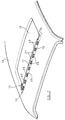
- the wind deflector 10 for the sunroof of a vehicle comprises an elongate body 11 which is located transversely of the vehicle adjacent leading edge 12 of the sunroof aperture 13.
- the elongate body 11 is supported at opposite ends on arms 15 which are pivotally attached to the vehicle at a level below the level of the vehicle roof 16.
- Resilient struts 17 act between the vehicle and the arms 15 to bias the arms 15 upwardly.
- the arms 15 are arranged such that they will be engaged by the sunroof, as it is closed; so that when the sunroof is closed the wind deflector 10 will be depressed into a storage area provided below the sunroof as illustrated in broken line in Figure 2; and when the sunroof is open, the wind deflector 10 will be deployed in an operational position in which the elongate body 11 extends above the roof level of the vehicle, as illustrated in full line in Figure 2.
- a sealing strip 20 is located in a longitudinal groove 21 along the lower edge of the elongate body 11, the sealing strip 20 having a lip formation 22 which sealingly engages the underside of the vehicle roof 16 when the wind deflector 10 is in its deployed position.
- the elongate body 11 when deployed, presents a leading face 25 which is inclined rearwardly.
- the elongate body 11 is castellated providing alternate sections 26 and 27, each typically 50 mm wide, of differing heights.
- the upper surfaces 28 of the lower sections 26 are located at about roof level, when the wind deflector 10 is deployed, while the taller sections 27 extend upwardly above the roof level to a height of about 25 mm.
- a vane 30 is provided on the upper surfaces 31 of the taller sections 27 and extends the full length of the elongate body 11, bridging the lower sections 26.
- the vane 30 is 20 mm wide.
- the leading portion 32 of the vane 30 is substantially parallel to the roof 16 and the trailing portion 33 of the vane 30 is inclined downwardly to the roof line at an angle of 20 degrees, when the wind deflector 10 is in its deployed position.
- the upper surfaces 28 of the lower sections 26 are parallel to the trailing portion 33 of vane 30.
- the taller sections 27 of the wind deflector 10 will deflect the air flow away from the open sunroof aperture 13, in conventional manner. Air will however also flow through the apertures 40 defined between the lower sections 26 and the vane 30, the air flowing therethrough being deflected downwardly into the vehicle compartment, through the sunroof aperture 13. These downward currents of air will break up the shear layer between the air flow passing above the sunroof aperture 13 and the air within the vehicle compartment, reducing the booming noise produced by resonant interaction therebetween. Furthermore, the downward currents of air will provide controlled ventilation to the vehicle compartment.
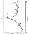
- Figure 3 is a plot of sound pressure against frequency for a conventional wind deflector with uniform cross section, operating with the sunroof fully open at a speed of 50 miles per hour.
- a sound pressure level peak 50 occurs which represents the booming noise. This peak is effectively removed by reducing speed to 20 miles per hour or increasing speed to more than 70 miles per hour.
- the boom peak is absent, but the broadband noise is of higher intensity than at 50 miles per hour.
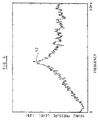
- Figure 4 is a plot similar to Figure 3 for a wind deflector having 50 mm castellations but without the vane 30 of the present invention.
- the sound pressure level of the peak 51 is reduced by about 5 dB as compared with the peak 50 produced by the conventional wind deflector, but still being of significant magnitude.
- Figure 5 is a plot similar to Figure 3 for a wind deflector similar to that represented by Figure 4 but with the upstanding edges of the castellations rounded to a radius of 8 mm. The plot again shows a reduction of about 3 or 4 dB in boom over the conventional wind deflector represented by Figure 3.
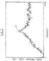
- Figure 6 is a plot similar to Figure 3 for a wind deflector similar to that represented by Figure 4 but with a 10 mm vane 30 formed across the upper edges of the taller sections of the castellations, the trailing edge of the vane being inclined downwardly at 20° in accordance with the present invention. While this again shows the peak 52, the magnitude of this peak is significantly reduced, by of the order of 20 dB, as compared with the wind deflector represented by Figure 3.
- Figure 7 is a plot similar to Figure 3 for a wind deflector similar to that represented by Figure 6 but with a 20 mm vane. As shown by this plot, there is a further reduction of the peak 53, by about 5 dB as compared with the wind deflector represented by Figure 6.
- Figure 8 is a plot similar to Figure 3 for a wind deflector similar to that represented by Figure 5 with a 20 mm vane formed across the upper surfaces of the castellations in accordance with the present invention. This plot again illustrates a similar reduction in sound level of the peak 54 to that of the wind deflector design represented by Figure 7.
- the dimensions of the wind deflector specified above are typical for conventional motor cars. For larger vehicles or for motor cars with large sunroofs, it may be necessary to scale up these dimensions. In other applications it may be necessary to provide sections of reduced height along only part of the elongate body.
Abstract
Description
- The present invention relates to wind deflectors for vehicle sunroofs.
- The sunroofs of vehicles, when open, produce significant noise levels which increase with the speed of the vehicle. Generally the noise is of a broadband nature due to pressure fluctuations resulting from the shear layer between the exterior air flow and the stationary air in the vehicle. In addition to this broadband noise, resonant interactions between the shear layer and the air inside the vehicle create low frequency pressure fluctuations which produce a booming noise over a critical speed range which is typically 30 to 70 miles per hour.
- Conventionally, wind deflectors of uniform profile have been fitted to the leading edge of the sunroof aperture, so that they extend above the line of the roof when the sunroof is open, thereby deflecting the air flow away from the sunroof aperture. Wind deflectors of this form significantly reduce the broadband noise and also reduce buffeting of air within the vehicle. However they are not effective in reducing the 'boom'. As a result, even with a wind deflector of this form, it is necessary to reduce the degree of opening of the sunroof in order to reduce the 'boom' to acceptable levels, when travelling at speeds at which intense boom would otherwise occur.
- It has been found, as disclosed for example in German patent specification numbers DE 3925808 and DE 4012569, that modifying the profile of the wind deflector, so that its upper edge is castellated, does provide some reduction in 'boom', but the 'boom' is still obtrusive at speeds within the critical range.
- The present invention provides a wind deflector with modified profile which will significantly reduce 'boom' at speeds within the critical range, with the sunroof fully open.
- According to one aspect of the present invention a wind deflector for the sunroof of a vehicle comprises an elongate body adapted to be located transversely of the vehicle along the leading edge of the sunroof aperture, the body extending above the level of the vehicle roof, the elongate body having alternate sections of different height, characterised in that vane formations extend between the upper edges of the taller sections to bridge the lower sections, the vane formations being adapted to deflect air passing between the vane formations and the lower sections down through the sunroof aperture.
- The vane formations interconnecting adjacent taller sections may conveniently be continued across the taller sections to form a continuous vane formation running the full length of the elongate body. Preferably, the leading edge of the vane formation is substantially parallel, that is inclined at an angle between + 5 degrees, to the roof line; while the trailing edge is inclined downwardly at an angle from 10 to 30 degrees to the roof line. The vane formation is preferably 10 to 30 mm wide. The faces defining the upper edge of the lower sections of the elongate body are preferably inclined at a similar angle to the trailing edge of the vane formation.
- The alternating taller and lower sections of the elongate body are preferably substantially equally spaced and of similar width. Typically the width of the taller and lower sections may be from 25 mm to 75 mm. The upper edge of the lower sections is preferably located at or below the level of the roof, while the taller sections extend beyond the roof level so that the vane formations are disposed above the roof level. Preferably when the wind deflector is in its operative position the vane formation is disposed at at least 15 mm above the roof level. The height of the vane formation is restricted by the need to accommodate the wind deflector in a limited space beneath the roof when the sunroof is closed, but typically the vane formation will be disposed at a height of between 15 mm and 30 mm above the roof level, when the wind deflector is in its operative position.
- In conventional manner, the elongate body is preferably located along the leading edge of the sunroof aperture on pivoting arms, the arms being biased upwardly so that the wind deflector will automatically be deployed when the sunroof is opened. The wind deflector being retracted below the roof, when the sunroof is closed.
- The invention is now described by way of example only, with reference to the accompanying drawings in which:-
- Figure 1 is a perspective view of a vehicle roof with a sunroof wind deflector in accordance with the present invention;
- Figure 2 is a sectional view of the wind deflector illustrated in Figure 1; and
- Figures 3 to 7 are plots of linear-weighted sound pressure levels against frequency for wind deflectors of varying configurations.
- As illustrated in Figures 1 and 2, the
wind deflector 10 for the sunroof of a vehicle comprises anelongate body 11 which is located transversely of the vehicle adjacent leadingedge 12 of thesunroof aperture 13. - The
elongate body 11 is supported at opposite ends onarms 15 which are pivotally attached to the vehicle at a level below the level of thevehicle roof 16.Resilient struts 17 act between the vehicle and thearms 15 to bias thearms 15 upwardly. Thearms 15 are arranged such that they will be engaged by the sunroof, as it is closed; so that when the sunroof is closed thewind deflector 10 will be depressed into a storage area provided below the sunroof as illustrated in broken line in Figure 2; and when the sunroof is open, thewind deflector 10 will be deployed in an operational position in which theelongate body 11 extends above the roof level of the vehicle, as illustrated in full line in Figure 2. - A
sealing strip 20 is located in alongitudinal groove 21 along the lower edge of theelongate body 11, thesealing strip 20 having alip formation 22 which sealingly engages the underside of thevehicle roof 16 when thewind deflector 10 is in its deployed position. - The
elongate body 11 when deployed, presents a leadingface 25 which is inclined rearwardly. Theelongate body 11 is castellated providingalternate sections upper surfaces 28 of thelower sections 26 are located at about roof level, when thewind deflector 10 is deployed, while thetaller sections 27 extend upwardly above the roof level to a height of about 25 mm. Avane 30 is provided on the upper surfaces 31 of thetaller sections 27 and extends the full length of theelongate body 11, bridging thelower sections 26. Thevane 30 is 20 mm wide. The leadingportion 32 of thevane 30 is substantially parallel to theroof 16 and thetrailing portion 33 of thevane 30 is inclined downwardly to the roof line at an angle of 20 degrees, when thewind deflector 10 is in its deployed position. Theupper surfaces 28 of thelower sections 26 are parallel to thetrailing portion 33 ofvane 30. - In operation, when the vehicle is in motion, the
taller sections 27 of thewind deflector 10 will deflect the air flow away from the opensunroof aperture 13, in conventional manner. Air will however also flow through theapertures 40 defined between thelower sections 26 and thevane 30, the air flowing therethrough being deflected downwardly into the vehicle compartment, through thesunroof aperture 13. These downward currents of air will break up the shear layer between the air flow passing above thesunroof aperture 13 and the air within the vehicle compartment, reducing the booming noise produced by resonant interaction therebetween. Furthermore, the downward currents of air will provide controlled ventilation to the vehicle compartment. - Figure 3 is a plot of sound pressure against frequency for a conventional wind deflector with uniform cross section, operating with the sunroof fully open at a speed of 50 miles per hour. As will be seen, at 50 miles per hour in addition to the general broadband noise, a sound
pressure level peak 50 occurs which represents the booming noise. This peak is effectively removed by reducing speed to 20 miles per hour or increasing speed to more than 70 miles per hour. At 90 miles per hour the boom peak is absent, but the broadband noise is of higher intensity than at 50 miles per hour. - Figure 4 is a plot similar to Figure 3 for a wind deflector having 50 mm castellations but without the
vane 30 of the present invention. In this case, the sound pressure level of thepeak 51 is reduced by about 5 dB as compared with thepeak 50 produced by the conventional wind deflector, but still being of significant magnitude. - Figure 5 is a plot similar to Figure 3 for a wind deflector similar to that represented by Figure 4 but with the upstanding edges of the castellations rounded to a radius of 8 mm. The plot again shows a reduction of about 3 or 4 dB in boom over the conventional wind deflector represented by Figure 3.
- Figure 6 is a plot similar to Figure 3 for a wind deflector similar to that represented by Figure 4 but with a 10
mm vane 30 formed across the upper edges of the taller sections of the castellations, the trailing edge of the vane being inclined downwardly at 20° in accordance with the present invention. While this again shows thepeak 52, the magnitude of this peak is significantly reduced, by of the order of 20 dB, as compared with the wind deflector represented by Figure 3. - Figure 7 is a plot similar to Figure 3 for a wind deflector similar to that represented by Figure 6 but with a 20 mm vane. As shown by this plot, there is a further reduction of the
peak 53, by about 5 dB as compared with the wind deflector represented by Figure 6. - Figure 8 is a plot similar to Figure 3 for a wind deflector similar to that represented by Figure 5 with a 20 mm vane formed across the upper surfaces of the castellations in accordance with the present invention. This plot again illustrates a similar reduction in sound level of the
peak 54 to that of the wind deflector design represented by Figure 7. - Various modifications may be made without departing from the invention. For example the dimensions of the wind deflector specified above are typical for conventional motor cars. For larger vehicles or for motor cars with large sunroofs, it may be necessary to scale up these dimensions. In other applications it may be necessary to provide sections of reduced height along only part of the elongate body.
Claims (15)
- A wind deflector (10) for the sunroof of a vehicle comprising an elongate body (11) adapted to be located transversely of the vehicle along the leading edge (12) of the sunroof aperture (13), the body (11) extending above the level of the vehicle roof (16), the elongate body (11) having alternate sections (26, 27) of different height, characterised in that vane formations (30) extend between the upper edges (31) of the taller sections (27) to bridge the lower sections (26), the vane formations (30) being adapted to deflect air passing between the vane formations (30) and the lower sections (26) down through the sunroof aperture (13).
- A wind deflector (10) according to Claim 1 characterised in that the vane formations (30) are continued across the taller sections (27) to form a continuous vane formation (30) running the full length of the elongate body (11).
- A wind deflector (10) according to Claim 1 or 2 characterised in that the leading edge (32) of the vane (30) is substantially parallel to the roof line.
- A wind deflector (10) according to Claim 3 characterised in that the leading edge (32) of the vane formation (30) is inclined at ± 5 degrees to the roof line.
- A wind deflector (10) according to any one of the preceding claims characterised in that the trailing edge (33) of the vane formation (30) is inclined downwardly at an angle of from 10 to 30 degrees to the roof line.
- A wind deflector (10) according to any one of the preceding claims characterised in that the vane formation (30) is between 10 and 30 mm wide.
- A wind deflector (10) according to any one of the preceding claims characterised in that the upper surfaces (28) of the lower sections (26) are substantially parallel to the trailing edge (33) of the vane formations (30).
- A wind deflector (10) according to any one of the preceding claims characterised in that the alternating taller and lower sections (26, 27) of the elongate body (11) are substantially equally spaced.
- A wind deflector (10) according to any one of the preceding claims characterised in that the alternating taller and lower sections (26, 27) of the elongate body (11) are of similar width.
- A wind deflector (10) according to any one of the preceding claims characterised in that the taller and lower sections (26, 27) of the elongate body (11) are from 25 mm to 75 mm wide.
- A wind deflector (10) according to any one of the preceding claims characterised in that the upper edge (28) of each lower section (26) is located at or below the level of the roof (16), the taller sections (27) extending beyond the roof level so that the vane formations (30) are disposed above the roof level.
- A wind deflector (10) according to Claim 11 characterised in that the vane formation (30) is disposed at least 15 mm above the roof level.
- A wind deflector (10) according to Claim 11 or 12 characterised in that the vane formation (30) is disposed at a height of between 15 mm and 30 mm above the roof level.
- A wind deflector (10) according to any one of the preceding claims characterised in that the elongate body (11) is mounted for movement between a deployed position in which it extends above the level of the roof (16) when the sunroof is open and a retracted position in which it is located beneath the sunroof when closed.
- A wind deflector (10) according to any one of the preceding claims characterised in that the elongate body (11) is sealed with respect to the leading edge (12) of the sunroof aperture (13).
Applications Claiming Priority (2)
| Application Number | Priority Date | Filing Date | Title |
|---|---|---|---|
| GB929218824A GB9218824D0 (en) | 1992-09-02 | 1992-09-02 | Wind defelctor for vehicle sunroof |
| GB9218824 | 1992-09-02 |
Publications (3)
| Publication Number | Publication Date |
|---|---|
| EP0586245A1 true EP0586245A1 (en) | 1994-03-09 |
| EP0586245B1 EP0586245B1 (en) | 1996-11-27 |
| EP0586245B2 EP0586245B2 (en) | 2000-04-19 |
Family
ID=10721456
Family Applications (1)
| Application Number | Title | Priority Date | Filing Date |
|---|---|---|---|
| EP93306921A Expired - Lifetime EP0586245B2 (en) | 1992-09-02 | 1993-09-01 | Wind deflector for vehicle sunroof |
Country Status (5)
| Country | Link |
|---|---|
| US (1) | US5431477A (en) |
| EP (1) | EP0586245B2 (en) |
| JP (1) | JP3375685B2 (en) |
| DE (1) | DE69306202T3 (en) |
| GB (1) | GB9218824D0 (en) |
Cited By (7)
| Publication number | Priority date | Publication date | Assignee | Title |
|---|---|---|---|---|
| EP0718136A1 (en) * | 1994-12-22 | 1996-06-26 | WEBASTO KAROSSERIESYSTEME GmbH | Wind deflector arrangement for vehicle roof |
| DE19915544A1 (en) * | 1999-04-07 | 2000-10-12 | Volkswagen Ag | Wind deflection device for roof aperture of vehicle, with additional wind deflector running transversely behind main one |
| EP1207070A3 (en) * | 2000-11-16 | 2003-05-07 | DaimlerChrysler AG | Wind deflector for sliding roof opening of vehicle |
| WO2004078506A1 (en) * | 2003-03-04 | 2004-09-16 | Daimlerchrysler Ag | Wind deflector for a motor vehicle sliding roof |
| EP1544015A1 (en) * | 2003-12-18 | 2005-06-22 | Inalfa Roof Systems Group B.V. | Wind deflector and open roof construction provided therewith |
| US7422274B2 (en) * | 2005-05-10 | 2008-09-09 | Cts Fahrzeug-Dachsysteme Gmbh | Roof for a motor vehicle |
| EP2353908A1 (en) * | 2008-12-05 | 2011-08-10 | Aisin Seiki Kabushiki Kaisha | Sunroof device and deflector |
Families Citing this family (13)
| Publication number | Priority date | Publication date | Assignee | Title |
|---|---|---|---|---|
| US5671970A (en) * | 1996-02-21 | 1997-09-30 | Webasto Sunroofs, Inc. | Wind deflector for motor vehicle sunroof |
| US6174025B1 (en) | 1999-08-31 | 2001-01-16 | Daimlerchrysler Corporation | Sun roof air dam wind noise reducer |
| DE10210142A1 (en) * | 2002-03-07 | 2003-09-18 | Arvinmeritor Gmbh | Wind deflector for a vehicle roof |
| US20040212219A1 (en) * | 2003-04-22 | 2004-10-28 | Weaver Darrick Charles | Active air foil |
| US20060290154A1 (en) * | 2005-06-24 | 2006-12-28 | Magna International Inc. | One piece long glass fiber molded cross rail with integrated end stanchions |
| US7621588B2 (en) * | 2006-01-10 | 2009-11-24 | Chrysler Group Llc | Deployable deflector for outside mirror |
| DE102009023890A1 (en) * | 2009-06-04 | 2010-12-16 | Continental Automotive Gmbh | Device for reducing buzzer noise in a motor vehicle |
| JP2013226884A (en) * | 2012-04-25 | 2013-11-07 | Yachiyo Industry Co Ltd | Sunroof device |
| DE102012111915B3 (en) * | 2012-12-07 | 2014-05-15 | Roof Systems Germany Gmbh | Wind deflector for a sunroof system |
| DE202013007447U1 (en) | 2013-08-22 | 2013-09-12 | Webasto SE | Wind deflector device on a vehicle roof opening |
| WO2015064040A1 (en) * | 2013-10-30 | 2015-05-07 | Nissan Motor Co., Ltd. | Deflector for sunroof apparatus |
| DE202013011443U1 (en) | 2013-12-20 | 2014-03-11 | Webasto SE | Wind deflector device on a vehicle roof opening |
| US9586464B2 (en) * | 2015-03-31 | 2017-03-07 | Nissan North America, Inc. | Vehicle sunroof wind deflector |
Citations (4)
| Publication number | Priority date | Publication date | Assignee | Title |
|---|---|---|---|---|
| US3311406A (en) * | 1963-08-28 | 1967-03-28 | Fritsch & Co O H G | Deflector for head wind |
| DE3925808A1 (en) * | 1989-08-04 | 1991-02-07 | Bayerische Motoren Werke Ag | Vehicle sliding sunroof, with wind deflector - has adjacent outwardly directed upwards and rearwards projections formed on deflector at its rear edge |
| DE4012569C1 (en) * | 1990-04-20 | 1991-05-23 | Mercedes-Benz Aktiengesellschaft, 7000 Stuttgart, De | Wind deflector for vehicle sliding roof panel - includes series of recesses along edge of deflector to promote turbulence only in external air flow |
| EP0490213A1 (en) * | 1990-12-11 | 1992-06-17 | Bayerische Motoren Werke Aktiengesellschaft | Noise and vibration damping device for vehicle opening exposed to a tangential air flow, especially for sliding roofs |
Family Cites Families (9)
| Publication number | Priority date | Publication date | Assignee | Title |
|---|---|---|---|---|
| DE1051657B (en) * | 1956-01-02 | 1959-02-26 | Volkswagenwerk Gmbh | Device for preventing natural vibrations of the air volume in the interior of motor vehicles with an open roof |
| US2878055A (en) * | 1956-03-28 | 1959-03-17 | Frank D Werner | Noise reducing device for vehicle windows |
| GB839306A (en) † | 1957-10-12 | 1960-06-29 | Daimler Benz Ag | Improvements relating to ventilating means in motor vehicles |
| DE2357906A1 (en) * | 1973-11-20 | 1975-05-28 | Hasse Friedrich W Dipl Ing | Wind-conducting face for openings in vehicle roofs - with movable flap arranged to guide air inside the vehicle |
| DE7822022U1 (en) † | 1978-07-22 | 1978-11-23 | Hamann, Ferdinand, 6074 Roedermark | Wind deflector for motor vehicles with a sliding roof |
| JPS5957014A (en) * | 1982-09-27 | 1984-04-02 | Honda Motor Co Ltd | Ventilation device for automobile |
| US4662671A (en) * | 1985-02-21 | 1987-05-05 | Carvalette Services Africa (Pty) Limited | Air deflector for motor vehicle |
| DE3611029A1 (en) † | 1986-04-02 | 1987-10-08 | Andreas Weber | Ventilation device for a wind-deflecting surface on motor vehicles with sliding roofs |
| DE3908750C1 (en) * | 1989-03-17 | 1990-06-07 | Rockwell Golde Gmbh, 6000 Frankfurt, De |
-
1992
- 1992-09-02 GB GB929218824A patent/GB9218824D0/en active Pending
-
1993
- 1993-08-31 US US08/114,739 patent/US5431477A/en not_active Expired - Fee Related
- 1993-09-01 DE DE69306202T patent/DE69306202T3/en not_active Expired - Fee Related
- 1993-09-01 EP EP93306921A patent/EP0586245B2/en not_active Expired - Lifetime
- 1993-09-02 JP JP21888293A patent/JP3375685B2/en not_active Expired - Fee Related
Patent Citations (4)
| Publication number | Priority date | Publication date | Assignee | Title |
|---|---|---|---|---|
| US3311406A (en) * | 1963-08-28 | 1967-03-28 | Fritsch & Co O H G | Deflector for head wind |
| DE3925808A1 (en) * | 1989-08-04 | 1991-02-07 | Bayerische Motoren Werke Ag | Vehicle sliding sunroof, with wind deflector - has adjacent outwardly directed upwards and rearwards projections formed on deflector at its rear edge |
| DE4012569C1 (en) * | 1990-04-20 | 1991-05-23 | Mercedes-Benz Aktiengesellschaft, 7000 Stuttgart, De | Wind deflector for vehicle sliding roof panel - includes series of recesses along edge of deflector to promote turbulence only in external air flow |
| EP0490213A1 (en) * | 1990-12-11 | 1992-06-17 | Bayerische Motoren Werke Aktiengesellschaft | Noise and vibration damping device for vehicle opening exposed to a tangential air flow, especially for sliding roofs |
Cited By (9)
| Publication number | Priority date | Publication date | Assignee | Title |
|---|---|---|---|---|
| EP0718136A1 (en) * | 1994-12-22 | 1996-06-26 | WEBASTO KAROSSERIESYSTEME GmbH | Wind deflector arrangement for vehicle roof |
| DE19915544A1 (en) * | 1999-04-07 | 2000-10-12 | Volkswagen Ag | Wind deflection device for roof aperture of vehicle, with additional wind deflector running transversely behind main one |
| EP1207070A3 (en) * | 2000-11-16 | 2003-05-07 | DaimlerChrysler AG | Wind deflector for sliding roof opening of vehicle |
| WO2004078506A1 (en) * | 2003-03-04 | 2004-09-16 | Daimlerchrysler Ag | Wind deflector for a motor vehicle sliding roof |
| EP1544015A1 (en) * | 2003-12-18 | 2005-06-22 | Inalfa Roof Systems Group B.V. | Wind deflector and open roof construction provided therewith |
| US7059668B2 (en) | 2003-12-18 | 2006-06-13 | Inalfa Roof Systems Group B.V. | Wind deflector and open roof construction provided therewith |
| US7422274B2 (en) * | 2005-05-10 | 2008-09-09 | Cts Fahrzeug-Dachsysteme Gmbh | Roof for a motor vehicle |
| EP2353908A1 (en) * | 2008-12-05 | 2011-08-10 | Aisin Seiki Kabushiki Kaisha | Sunroof device and deflector |
| EP2353908A4 (en) * | 2008-12-05 | 2012-05-09 | Aisin Seiki | Sunroof device and deflector |
Also Published As
| Publication number | Publication date |
|---|---|
| DE69306202D1 (en) | 1997-01-09 |
| GB9218824D0 (en) | 1992-10-21 |
| JP3375685B2 (en) | 2003-02-10 |
| EP0586245B1 (en) | 1996-11-27 |
| JPH06156088A (en) | 1994-06-03 |
| EP0586245B2 (en) | 2000-04-19 |
| US5431477A (en) | 1995-07-11 |
| DE69306202T3 (en) | 2001-04-19 |
| DE69306202T2 (en) | 1997-03-20 |
Similar Documents
| Publication | Publication Date | Title |
|---|---|---|
| EP0586245B1 (en) | Wind deflector for vehicle sunroof | |
| US5544931A (en) | Aerodynamic stabilizer for use with a motor vehicle | |
| EP0374421A3 (en) | Wind deflectors for motor vehicle roofs, removable roof segments or the like | |
| US5671970A (en) | Wind deflector for motor vehicle sunroof | |
| US5178436A (en) | Draft deflector for sliding roofs, removable roof sections or the like of motor vehicles | |
| US9586464B2 (en) | Vehicle sunroof wind deflector | |
| US3973478A (en) | Air deflection for sliding roofs of motor vehicles | |
| JP3663544B2 (en) | Bridge | |
| US6227613B1 (en) | Vehicle with a sliding fabric roof and a front spoiler thereon | |
| US6244654B1 (en) | Motor vehicle sunroof with reduced buffeting noise | |
| EP1010562B1 (en) | Deflector of vehicular sunroof | |
| JP2675168B2 (en) | Vehicle | |
| EP0677409A1 (en) | Sun roofs for vehicles | |
| JP3329140B2 (en) | Front window side structure of vehicle | |
| EP0266893B1 (en) | Vehicle aerodynamics | |
| JP3309603B2 (en) | Air deflector front seal structure | |
| JP3253554B2 (en) | Drainage structure of windshield mall | |
| JP4083368B2 (en) | Vehicle seal structure | |
| JP3679257B2 (en) | Roof side weather strip | |
| KR100482505B1 (en) | Door inside belt weather strip for vehicle | |
| JPH0316734Y2 (en) | ||
| JP2548408Y2 (en) | Deflector on body roof | |
| JP3297646B2 (en) | Door seal structure for vehicle with fixed body triangle window | |
| CA1113526A (en) | Aerodynamic drag-reducing shield for mounting on the front of a cargo carrying compartment of a road vehicle | |
| EP0173237A2 (en) | Construction for mounting slider of door glass in motor vehicle |
Legal Events
| Date | Code | Title | Description |
|---|---|---|---|
| PUAI | Public reference made under article 153(3) epc to a published international application that has entered the european phase |
Free format text: ORIGINAL CODE: 0009012 |
|
| AK | Designated contracting states |
Kind code of ref document: A1 Designated state(s): DE FR GB IT SE |
|
| 17P | Request for examination filed |
Effective date: 19940902 |
|
| 17Q | First examination report despatched |
Effective date: 19951017 |
|
| GRAH | Despatch of communication of intention to grant a patent |
Free format text: ORIGINAL CODE: EPIDOS IGRA |
|
| GRAH | Despatch of communication of intention to grant a patent |
Free format text: ORIGINAL CODE: EPIDOS IGRA |
|
| GRAA | (expected) grant |
Free format text: ORIGINAL CODE: 0009210 |
|
| AK | Designated contracting states |
Kind code of ref document: B1 Designated state(s): DE FR GB IT SE |
|
| PG25 | Lapsed in a contracting state [announced via postgrant information from national office to epo] |
Ref country code: IT Free format text: LAPSE BECAUSE OF FAILURE TO SUBMIT A TRANSLATION OF THE DESCRIPTION OR TO PAY THE FEE WITHIN THE PRE;WARNING: LAPSES OF ITALIAN PATENTS WITH EFFECTIVE DATE BEFORE 2007 MAY HAVE OCCURRED AT ANY TIME BEFORE 2007. THE CORRECT EFFECTIVE DATE MAY BE DIFFERENT FROM THE ONE RECORDED.SCRIBED TIME-LIMIT Effective date: 19961127 |
|
| ET | Fr: translation filed | ||
| REF | Corresponds to: |
Ref document number: 69306202 Country of ref document: DE Date of ref document: 19970109 |
|
| PG25 | Lapsed in a contracting state [announced via postgrant information from national office to epo] |
Ref country code: SE Effective date: 19970227 |
|
| PLBQ | Unpublished change to opponent data |
Free format text: ORIGINAL CODE: EPIDOS OPPO |
|
| PLBI | Opposition filed |
Free format text: ORIGINAL CODE: 0009260 |
|
| PLBF | Reply of patent proprietor to notice(s) of opposition |
Free format text: ORIGINAL CODE: EPIDOS OBSO |
|
| 26 | Opposition filed |
Opponent name: WEBASTO KAROSSERIESYSTEME GMBH Effective date: 19970826 |
|
| PLBF | Reply of patent proprietor to notice(s) of opposition |
Free format text: ORIGINAL CODE: EPIDOS OBSO |
|
| PLBF | Reply of patent proprietor to notice(s) of opposition |
Free format text: ORIGINAL CODE: EPIDOS OBSO |
|
| PLAW | Interlocutory decision in opposition |
Free format text: ORIGINAL CODE: EPIDOS IDOP |
|
| PLAW | Interlocutory decision in opposition |
Free format text: ORIGINAL CODE: EPIDOS IDOP |
|
| PUAH | Patent maintained in amended form |
Free format text: ORIGINAL CODE: 0009272 |
|
| STAA | Information on the status of an ep patent application or granted ep patent |
Free format text: STATUS: PATENT MAINTAINED AS AMENDED |
|
| 27A | Patent maintained in amended form |
Effective date: 20000419 |
|
| AK | Designated contracting states |
Kind code of ref document: B2 Designated state(s): DE FR GB IT SE |
|
| ET3 | Fr: translation filed ** decision concerning opposition | ||
| REG | Reference to a national code |
Ref country code: GB Ref legal event code: 746 Effective date: 20010720 |
|
| REG | Reference to a national code |
Ref country code: GB Ref legal event code: IF02 |
|
| PGFP | Annual fee paid to national office [announced via postgrant information from national office to epo] |
Ref country code: FR Payment date: 20060906 Year of fee payment: 14 |
|
| PGFP | Annual fee paid to national office [announced via postgrant information from national office to epo] |
Ref country code: DE Payment date: 20060929 Year of fee payment: 14 |
|
| PG25 | Lapsed in a contracting state [announced via postgrant information from national office to epo] |
Ref country code: DE Free format text: LAPSE BECAUSE OF NON-PAYMENT OF DUE FEES Effective date: 20080401 |
|
| REG | Reference to a national code |
Ref country code: FR Ref legal event code: ST Effective date: 20080531 |
|
| PG25 | Lapsed in a contracting state [announced via postgrant information from national office to epo] |
Ref country code: FR Free format text: LAPSE BECAUSE OF NON-PAYMENT OF DUE FEES Effective date: 20071001 |
|
| PGFP | Annual fee paid to national office [announced via postgrant information from national office to epo] |
Ref country code: GB Payment date: 20080808 Year of fee payment: 16 |
|
| GBPC | Gb: european patent ceased through non-payment of renewal fee |
Effective date: 20090901 |
|
| PG25 | Lapsed in a contracting state [announced via postgrant information from national office to epo] |
Ref country code: GB Free format text: LAPSE BECAUSE OF NON-PAYMENT OF DUE FEES Effective date: 20090901 |