EP0533359A2 - Electric propulsion motor for marine vehicles - Google Patents
Electric propulsion motor for marine vehicles Download PDFInfo
- Publication number
- EP0533359A2 EP0533359A2 EP92307721A EP92307721A EP0533359A2 EP 0533359 A2 EP0533359 A2 EP 0533359A2 EP 92307721 A EP92307721 A EP 92307721A EP 92307721 A EP92307721 A EP 92307721A EP 0533359 A2 EP0533359 A2 EP 0533359A2
- Authority
- EP
- European Patent Office
- Prior art keywords
- rotor
- motor
- shaft
- stator
- electric propulsion
- Prior art date
- Legal status (The legal status is an assumption and is not a legal conclusion. Google has not performed a legal analysis and makes no representation as to the accuracy of the status listed.)
- Granted
Links
Images


Classifications
-
- H—ELECTRICITY
- H02—GENERATION; CONVERSION OR DISTRIBUTION OF ELECTRIC POWER
- H02K—DYNAMO-ELECTRIC MACHINES
- H02K21/00—Synchronous motors having permanent magnets; Synchronous generators having permanent magnets
- H02K21/12—Synchronous motors having permanent magnets; Synchronous generators having permanent magnets with stationary armatures and rotating magnets
- H02K21/24—Synchronous motors having permanent magnets; Synchronous generators having permanent magnets with stationary armatures and rotating magnets with magnets axially facing the armatures, e.g. hub-type cycle dynamos
-
- B—PERFORMING OPERATIONS; TRANSPORTING
- B63—SHIPS OR OTHER WATERBORNE VESSELS; RELATED EQUIPMENT
- B63H—MARINE PROPULSION OR STEERING
- B63H21/00—Use of propulsion power plant or units on vessels
- B63H21/12—Use of propulsion power plant or units on vessels the vessels being motor-driven
- B63H21/17—Use of propulsion power plant or units on vessels the vessels being motor-driven by electric motor
-
- B—PERFORMING OPERATIONS; TRANSPORTING
- B63—SHIPS OR OTHER WATERBORNE VESSELS; RELATED EQUIPMENT
- B63H—MARINE PROPULSION OR STEERING
- B63H23/00—Transmitting power from propulsion power plant to propulsive elements
- B63H23/22—Transmitting power from propulsion power plant to propulsive elements with non-mechanical gearing
- B63H23/24—Transmitting power from propulsion power plant to propulsive elements with non-mechanical gearing electric
-
- H—ELECTRICITY
- H02—GENERATION; CONVERSION OR DISTRIBUTION OF ELECTRIC POWER
- H02K—DYNAMO-ELECTRIC MACHINES
- H02K29/00—Motors or generators having non-mechanical commutating devices, e.g. discharge tubes or semiconductor devices
- H02K29/06—Motors or generators having non-mechanical commutating devices, e.g. discharge tubes or semiconductor devices with position sensing devices
-
- H—ELECTRICITY
- H02—GENERATION; CONVERSION OR DISTRIBUTION OF ELECTRIC POWER
- H02K—DYNAMO-ELECTRIC MACHINES
- H02K5/00—Casings; Enclosures; Supports
- H02K5/04—Casings or enclosures characterised by the shape, form or construction thereof
- H02K5/16—Means for supporting bearings, e.g. insulating supports or means for fitting bearings in the bearing-shields
- H02K5/173—Means for supporting bearings, e.g. insulating supports or means for fitting bearings in the bearing-shields using bearings with rolling contact, e.g. ball bearings
-
- H—ELECTRICITY
- H02—GENERATION; CONVERSION OR DISTRIBUTION OF ELECTRIC POWER
- H02K—DYNAMO-ELECTRIC MACHINES
- H02K7/00—Arrangements for handling mechanical energy structurally associated with dynamo-electric machines, e.g. structural association with mechanical driving motors or auxiliary dynamo-electric machines
- H02K7/14—Structural association with mechanical loads, e.g. with hand-held machine tools or fans
-
- B—PERFORMING OPERATIONS; TRANSPORTING
- B63—SHIPS OR OTHER WATERBORNE VESSELS; RELATED EQUIPMENT
- B63H—MARINE PROPULSION OR STEERING
- B63H23/00—Transmitting power from propulsion power plant to propulsive elements
- B63H23/32—Other parts
- B63H23/321—Bearings or seals specially adapted for propeller shafts
- B63H2023/325—Thrust bearings, i.e. axial bearings for propeller shafts
-
- H—ELECTRICITY
- H02—GENERATION; CONVERSION OR DISTRIBUTION OF ELECTRIC POWER
- H02K—DYNAMO-ELECTRIC MACHINES
- H02K2201/00—Specific aspects not provided for in the other groups of this subclass relating to the magnetic circuits
- H02K2201/06—Magnetic cores, or permanent magnets characterised by their skew
Definitions
- This invention relates generally to electric motors and more particularly to propulsion motors for marine vehicles.
- Marine vehicles typically employ one or more rotating propellers disposed beneath the water line of the vessel for surface vessels or disposed within a portion of the hull of submersible vessels.
- the propellers in submersible systems have been driven by diesel power, steam turbines or electric motors mounted within the hull of a vessel.
- a propeller shaft extends through the hull to the propeller mounted on the shaft outside the hull.
- Such systems have the disadvantage of noise and vibration radiating from the rotating components.
- Such systems typically occupy a great deal of the interior hull space.
- the motor typically, is a primary source of noise and vibration.
- the source of such noise in an electric motor is often torque ripple due, for example, to cogging, i.e., variations in magnetic flux that are related to rotor position, reluctance, and the mechanical coupling between the rotor and propeller shaft.
- Another object of the invention is to isolate the noise generated by the motor from the propeller shaft by providing a sound isolating coupling within the open center of the motor so as not to increase the axial length of the motor and related equipment.
- a further object of the invention is to reduce the torque ripple in an electric motor due to cogging and thereby reduce noise.
- Another object of the invention is to provide an improved arrangement for handling and distributing electrical and mechanical forces on the rotor, such arrangement including a large diameter circumferential thrust bearing and journal bearing.
- the electric propulsion motor of the present invention is substantially wheel-shaped and has as its major components a disk-shaped rotor and two disk-shaped stators.
- a single motor is mounted in the hull of a vessel and is axially aligned with a longitudinal axis of the vessel.
- two motors with counter-rotating propellers are installed.
- the shape of the motor, with a large diameter relative to its axial length, is advantageous in marine vehicles because it significantly reduces the total stack-up length of the motor and related couplings. This provides greater interior hull space for other equipment.
- the large diameter, open center of the motor permits the installation of a sound isolation coupling between the rotor and the propeller shaft. Such coupling does not add to the axial stack-up length of the motor assembly because it is located within the interior of the motor.
- the two stators mounted on either side of the rotor and separated therefrom by axial air gaps, are provided with armature windings that are fed by a controlled current source (power inverter modules).
- the rotor magnetic field is provided by permanent magnets mounted on a rotor disk.
- the rotor permanent magnet field reacts with a rotating magnetic field of the stators to produce rotational torque upon the rotor, which is transferred to the propeller shaft through the sound isolation coupling.
- Thrust bearings for the rotor are mounted circumferentially around each side of the rotor. This circumferential thrust bearing can be a single annular bearing or a plurality of spaced bearing assemblies.
- the rotor is supported on a radial bearing.
- Each of the stators includes teeth and slots, with coils (conductors) being wound within the slots.
- the rotor includes axially magnetized permanent magnets and the magnet flux crosses the air gap on both sides of the rotor. As the magnet pole passes the slots in the stators, cogging will result due to the preferred orientation of the pole with the teeth, where reluctance is minimum. This cogging gives rise to a component of torque ripple. In the present invention, cogging may be minimized by staggering the stators such that the teeth of one stator are oriented opposite the slots of the stator.
- stator slots are skewed, i.e. rather than being parallel to a diameter of the stator, the slots lie at an angle to the diameter.
- the magnet poles may also be skewed such that a diameter of the rotor will not be collinear with a central longitudinal dividing line of the magnet pole.
- the sides of each pole are slightly curved.
- a large number of permanent magnet poles are formed in the rotor, seventy-eight in the embodiment shown in the drawings.
- Torque ripple is also reduced by taking advantage of the fact that most of the total variation in torque is a repeatable function of rotor position.
- the present invention utilizes high speed switching elements and pulse width modulation to provide precise control over the current applied to the stator windings.
- the shaft-position-dependent information needed to compensate for torque variations is stored in one or more programmable read-only memories (PROMs).
- PROMs programmable read-only memories
- a first aspect of the invention provides an electric propulsion motor for marine vehicles comprising: a disk-shaped rotor and two coaxial disk-shaped stators, said rotor being separated from each of said stators in an axial direction by an air gap: said rotor including a plurality of permanent magnets that produce a first magnetic field; each stator comprising an armature winding that is connected to a source of electrical current to produce a second magnetic field, said first and second magnetic fields being capable of interacting to create an electromagnetic torque; means for coupling said rotor to a propeller shaft for transferring said torque from said rotor to said shaft, and means for detecting the angle of said shaft; a current control means for receiving a current control signal and for employing pulse width modulation to control said source of electrical current; said control means including means for storing compensation information related to torque variations that are a function of shaft angle; said current control means including means connected and responsive to said shaft angle detecting means for selecting said compensation information as a function of shaft angle and for combining said compensation information with said current control
- Said islolating means may comprise an elastomer
- the electric propulsion motor may further include an annular plate connected to and extending from said rotor and a disk connected to and extending from said propeller shaft and wherein said sound isolating means is sandwiched between said disk and said plate.
- a second aspect of the invention provides an electric propulsion motor for marine vehicles comprising: a disk-shaped rotor and two coaxial disk-shaped stators, said rotor being separated from each of said stators in an axial direction by an air gap; said rotor including a plurality of permanent magnets that produce a first magnetic field; each stator comprising an armature winding that is connected to a source of electrical current to produce a second field, said first and second magnetic fields being capable of interacting to create an electromagnetic torque; means for coupling said rotor to a propeller shaft for transferring said torque from said rotor to said shaft, and means for detecting the angle of said shaft; a current control means for receiving a current control signal and for employing pulse width modulation to control said source of electrical current; said control means including means for storing compensation information related to torque variationg that are a function of shaft angle; said current control means including means connected and responsive to said shaft angle detecting means for selecting said compensation information as a function of shaft angle and for combining said compensation information with said current control
- Said circumferential thrust bearings may comprise a plurality of spaced bearing assemblies.
- Said spaced bearing assemblies may comprise tilting pad thrust bearings.
- Said circumferential thrust bearings may alternatively comprise solid annular bearings.
- Said rotor bearing surfaces may comprise annular runners.
- Said circumferential thrust bearings may be located in proximity to a magnetically active portion of said rotor.
- a third aspect of the invention provides an electric propulsion motor for marine vehicles comprising: a disk-shaped rotor and two coaxial disk-shaped stators, said rotor being separated from each of said stators in an axial direction by an air gap; said rotor including a plurality of Permanent magnets that produce a first magnetic field; each stator comprising an armature winding that is connected to a source of electrical current to produce a second magnetic field, said first and second magnetic fields being capable of interacting to create an electromagnetic torque; means for coupling said rotor to a propeller shaft for transferring said torque from said rotor to said shaft, and means for detecting the angle of said shaft; a current control means for receiving a current control signal and for employing pulse width modulation to control said source of electrical current; said control means including means for storing compensation information related to torque variations that are a function of shaft angle; said current control means including means connected and responsive to said shaft angle detecting means for selecting said compensation information as a function of shaft angle and for combining said compensation information with said current control
- Said radial bearing may comprises a plain cylindrical bearing.
- Said radial bearing may alternatively comprise a plurality of spaced bearing assemblies.
- Said means for coupling said propeller shaft to said rotor may includes means within the motor for isolating said shaft from sound produced by said motor.
- Said sound isolating means may comprises an elastomer.
- the motor may further include an annular plate connected to and extending from said rotor and a disk connected to and extending from said propeller shaft and wherein said sound isolating means is sandwiched between said disk and said plate.
- the motor may further include circumferencial thrust bearings facing both sides of said rotor, said rotor including bearing surfaces for engagement with said thrust bearings.
- Said circumferential thrust bearings may comprise a plurality of spaced bearing assemblies.
- Said spaced bearing assemblies may comprise tilting pad thrust bearings.
- Said circumferential thrust bearings may comprise solid annular bearings.
- Said rotor bearing surfaces may comprise annular runners.
- Said circumferential thrust bearings may be located in proximity to a magnetically active portion of said rotor.
- the motor may further include a radial bearing for supporting said rotor.
- Said radial bearing may comprise a plain cylindrical bearing.
- Said radial bearing may comprise a plurality of spaced bearing assemblies.
- Each said stator may includes a plurality of teeth separated by a like plurality of slots, said slots including stator coils; and said two stators may be staggered on either side of said rotor positioned such that the teeth of a first one of said stators are positioned axially across the rotor opposite the slots of a second one of said stators, whereby a cogging component of torque ripple is minimized.
- Each said stator may include a plurality of teeth separated by a like plurality of slots, said slots including stator coils; and said slots in each said stator being skewed such that they lie at an angle to a diameter of each said stator, whereby a cogging component of torque ripple is minimized.
- Said rotor magnets may be configured with alternating north and south poles around the circumference of said rotor; and said poles may be skewed such that diameters of said rotor are not collinear with lines that divide each pole along its longitudinal axis, whereby a cogging component of torque ripple is minimized.
- Each said pole may have a skewed shape in that at least one side of each pole is curved.
- Said rotor may comprise at least fifty permanent magnet poles.
- Said current control means may include insulated gate bipolar transistors (IGBTs) as switching elements.
- IGBTs insulated gate bipolar transistors
- Said means for storing compensation information may comprise at least one programmable read only memory (PROM).
- PROM programmable read only memory
- Said means for combining said compensation information with said current control signal may include at least one multiplier.
- the motor may further include means for mounting said motor within a hull of said marine vehicle, said mounting means including means for isolating said hull from sound and vibration generated by said motor.
- Said marine vehicle may include two electric propulsion motors and two propeller shafts, wherein a first motor rotates a first propeller shaft in a first rotating direction and a second motor rotates a second propeller shaft in a second direction that is counter to said first direction.
- Said current control means may employ a pulse width modulation frequency of approximately 20 KHz.
- Figure 1 is a perspective view of a preferred embodiment of the propulsion motor of the present invention.
- Figure 2 is a cross-sectional view along the line 2-2 of Figure 1.
- Figure 3 is an enlarged view of the upper half of the assembly depicted in Figure 2.
- Figure 4 is an enlarged view of the rotor and torque plate shown in Figure 3.
- Figure 5 is an enlarged cross-sectional view of one stator shown in Figures 2 and 3.
- Figure 6 is a cross-sectional view illustrating the mounting of the propulsion motor of the present invention in the hull of a ship.
- Figure 7 is a partial cross-sectional view illustrating the single motor embodiment of the present invention.
- Figure 8 is a partial cross-sectional view illustrating the dual counter-rotating embodiment of the present invention.
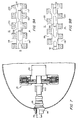
- Figure 9A is a representative view of two stators in alignment.
- Figure 9B is a representative view of the staggered stator feature of the present invention.
- Figure 10A is a representative view of a straight slot stator arrangement.
- Figure 10B is a representative view of the skewed stator slot feature of the present invention.
- Figure 11A is a representative view of a straight magnet pole arrangement.
- Figure 11B is a representative view of the skewed magnet pole arrangement of the present invention.
- Figure 12 illustrates a partial stator winding slot arrangement
- Figure 13 is a block diagram depicting the stator current control system of the present invention.
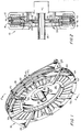
- FIG 1 shows a perspective view of a preferred embodiment of the propulsion motor of the present invention.
- the motor 10 comprises three major components, two stators and a rotor (not individually visible in Figure 1).
- the rotor 16 is disposed between the two stators 12, 14 (as shown in Figure 2).
- the motor 10 is substantially wheel-shaped, having a large diameter relative to its axial length.
- the short axial length of the motor is advantageous in marine vehicles. For example, the total length of the engine room is reduced due to the significantly shorter stack-up length of the shafting, coupling, thrust bearing and motor. See Figure 7, for example. This provides greater available interior hull space for equipment, storage, crew quarters, weapon systems, etc.
- each stator 12, 14 is also joined to large coupling flanges 24 that permit the motor 10 to be mounted in the ship's housing (see Figure 6, for example).
- the rotor 16 and stators 12 and 14 are substantially disk-shaped (see Figures 11 and 10, respectively, for example), with a large, open center. Referring to Figure 1, this large, open center is utilized in the present invention for passage of the ship's hollow propeller shaft 26 and for the unique rotor/propeller shaft coupling arrangement of the present invention.
- an annular rotor torque plate 28 (connected to the rotor 16 as shown in Figure 2) extends radially inward toward propeller shaft 26.
- shaft disk 30 Coupled to and extending radially outward from propeller shaft 26 is shaft disk 30, which is connected (e.g. by welding) to the outer wall 27 of propeller shaft 26.
- the outer perimeter of plate 28 and disk 30 overlap, as best shown in Figure 2.
- Coupling 32 may be made of any suitable flexible material, preferably an elastomer, and is held in place under pressure between plate 28 and disk 30, which are held together by bonding, for example.
- This unique coupling arrangement provides an effective means for isolating noise-inducing motor vibrations from the propeller output shaft. This is accomplished within the open center of the motor and thus adds no additional axial length to the motor assembly.
- FIG 1 also shows the arrangement of the inverter modules 34 located around the circumference of both stators 12 and 14.
- Inverter modules 34 function as a controlled current source for the stator coils as will be discussed hereinafter in more detail.
- Each group of five (5) inverter modules is cooled by a cold plate 36.
- Each plate is in the form of a segment of an annulus.
- Each plate 36 is divided longitudinally by a wall into two channels, with the wall open at one end to connect the two channels. Cooling fluid enters the radially outer channel through conduit 38, traverses the length of the plate, passes through the open end of the dividing wall and returns through the radially inner channel, exiting at conduit 40.
- Conduits 38 and 40 will be connected to an appropriate cool fluid supply and warm water disposal, respectively, which are not shown in Figure 1.
- Figure 2 shows a cross-section of the motor assembly and Figure 3 is an enlarged cross-sectional view of the upper half of the motor. The cross-hatching has been omitted for clarity.
- the upper and lower halves of the motor are identical.
- the motor 10 will typically be mounted in the hull of a vessel in surrounding relationship to the propeller shaft 26.
- the ship's thrust and journal bearings, which support the propeller shaft and transfer the propeller thrust to the ship, are conventional and shown generally as 42.
- Figure 2 best illustrates the improved rotor/propeller shaft coupling of the present invention, in which the annular rotor torque plate 28 is connected (e.g. by welding) to a portion 44 of rotor 16.
- propeller shaft disk 30 is connected to and extends radially from propeller shaft 26.
- Plate 28 and disk 30 are connected at their overlapping perimeter portions by bonding or other suitable means that will not contribute to the transmission of noise and/or vibrations. Sandwiched in between these two portions is sound attenuating coupling 32.
- Coupling 32 preferably an elastomer, is flexible and can absorb motor vibrations and isolate them from the propeller shaft, thus reducing transmission of noise into the shaft and thence into the hull structure and surrounding water.
- motor torque will be applied to the propeller shaft through plate 28, coupling 32 and disk 30. The torque is produced as a result of a rotating magnetic field set up by alternating current in the windings of stators 12, 14. The rotating magnetic field reacts with the permanent magnetic field in the rotor, which rotates on an annular bearing surface, as will be described.
- Rotor 16 is interposed between stators 12 and 14 and is separated therefrom by axial air gaps 50 and 52, respectively.
- Rotor 16 generally comprises permanent magnet material portion 46 and non-magnetic portions 44 and 48.
- Stator 12 generally comprises a mechanical support structure 54, stator backiron 56, and windings mounted in slots shown generally as 58.
- a gusset 66 is provided for stator 12 structure reinforcement.
- stator 14 has a support structure 60, backiron 62, and windings in slots 64.
- the two stator support structures are joined together at flange members 18 and 20 by bolt nut combinations 22 or other suitable fasteners.
- reinforcing members 70 and 72 are provided at intervals around the circumference (see Figure 1) of structures 54 and 60, respectively.
- each stator 12, 14 Located axially outside of each stator 12, 14 are inverter modules 34. Interposed between the stator support structure and inverter modules 34 is a cold plate 36. As discussed previously with reference to Figure 1, each cold plate is divided by a wall, labeled 68 in Figure 3, to guide cooling water along the length of each plate.
- circumferential thrust bearings 74 and radial bearing 76 support rotor 16 and counter and distribute electrical and mechanical forces in the motor to maintain the position of the rotor relative to the stators.
- Thrust bearings 74 are mounted to stator support structures 54 and 60 on each side of rotor 16 in proximity to the magnetically active portion, i.e. area 46, of the rotor.
- the thrust bearing assemblies may comprise solid annular bearings or a plurality of spaced thrust bearing assemblies (e.g. conventional tilting pad type) mounted on a rotor-facing circumferential surface of each stator support structure.
- the bearing surfaces of rotor 16 will comprise annular runners 78 and 80, which are attached to rotor 16 as will be described with reference to Figure 4.
- Rotor 16 is supported on radial bearing 76, which may comprise a plain cylindrical bearing or a plurality of spaced bearing assemblies mounted on a rotor facing circumferential surface of stator support structure 54 and is remote from the propeller shaft 26.
- the radial bearing surface of rotor 16 will comprise annular runner 82.
- FIG 4 is an enlarged view of the rotor 16 and torque plate 28 shown in Fig. 3.
- the primary component of rotor 16 is a disk made of non-magnetic materials such as stainless steel, titanium, or composites.
- non-magnetic disk portions are labeled 44 and 48.
- permanent magnets are mounted in openings in the rotor disk. These permanent magnets mounted in the rotor disk are illustrated generally as area 46.
- the magnets may be placed directly in the openings and secured with an epoxy adhesive.
- the magnets may be placed in magnet holders and the holders mechanically fastened inside the rotor openings.
- mechanical shields 84 with fasteners 86 passing through both shields secure the magnets.
- the permanent magnets are neodymium iron boron. Permanent magnets are rated by their energy product. The energy product is the product of B, magnetic flux density, and H, magnetic field intensity. The neodymium iron boron magnets are commercially available with energy products exceeding 30 megagauss oersteds.
- An advantage of the permanent-field rotor is that it eliminates the need for rotary electrical contacts and must absorb only very low heat losses. Thus, it does not require a complex or bulky cooling system. Further, the permanent magnets provide high power density when compared to other designs and are of relatively light weight.
- Figure 4 also illustrates the mounting of annular runners 78, 80 and 82.
- Annular runner 78 is mounted on the outside of rotor torque plate 28 and runner 80 is mounted on the outside of mechanical shield 84. Both runners 78 and 80 are secured by inner fastener 86.
- Annular runner 82 is mounted against the lower surface of portion 44 of the rotor disk and is secured in place by suitable fastener 88.
- FIG. 5 is an enlarged cross-sectional view of stator 12 shown in Figures 2 and 3, it being understood that stator 14 will comprise the same structural components in an opposite orientation.
- the outline of the stator coils is represented by 58 and the stator backiron is represented by a series of rectangular bands, labeled 56.
- Figure 5 also illustrates the stator cold plate 112, not shown in the prior, less detailed, figures.
- Within stator cold plate 112 is a series of cooling channels 114 that serve to disperse heat generated by the stator coils.
- the backiron core 56, with surrounding coils 58, is connected to stator cold plate 112 by retaining pins, e.g. pin 115. This subassembly is then connected to the stator support structure 54 ( Figure 2) by suitable fasteners 116.
- Figure 6 illustrates, in a cross-sectional view through the hull 90 of a marine vehicle, a typical mounting arrangement for motor 10.
- Motor 10 is mounted coaxially with the ship's propeller shaft 26 by securing large coupling flanges 24 to foundation members 92 in the interior of the hull.
- the motor will be mounted with some form of sound isolation member 94 (e.g. an elastomeric block) interposed between flanges 24 and foundation members 92.
- Figure 7 is a side cross-sectional view through the hull 90 of a marine vehicle, illustrating a typical arrangement of the propulsion motor of the present invention in a ship. Segments of a typical propeller shaft 26 mounting arrangement are shown generally, for example, stern tube with bearing 96, shaft seal 98, shaft coupling 100, and ship's thrust and journal bearing assembly 42.
- FIG 8 is a representation illustrating a dual counter-rotating propeller shaft embodiment of the present invention.
- an outer propeller shaft 26 is driven by propulsion motor 10
- an inner propeller shaft 102 is driven by propulsion motor 104 in a rotating direction opposite to the rotating direction of outer shaft 26.
- the blades of the propeller coupled to outer shaft 26 will be of opposite pitch to the blades of the propeller coupled to inner shaft 102.
- Some of the major components shown in Figure 7 are stern tube with bearings 96 for both shafts, outer shaft seal 98, outer shaft coupling 100, ship's thrust and journal bearing assembly 42 for the outer shaft, inner/outer shaft seal 106, inner shaft coupling 108, and ship's thrust and journal bearing assembly 110 for the inner shaft.
- Dual counter-rotating propellers are used because of the hydrodynamic advantages that are realized. These advantages help in reducing power loss.
- a principal advantage of the present invention is noise reduction. Noise results in electric motors, in part, because of mechanical vibrations caused by unstable and undesirable magnetic attractive forces, known as torque ripple.
- torque ripple One component in the undesirable variation in torque is referred to as cogging torque, which occurs when the motor has armature teeth.
- axially magnetized permanent magnets 46 are mounted on the rotor 16.
- Stators 12 and 14 are located on either side of rotor 16 and are separated therefrom by axial air gaps 50 and 52. The magnet flux crosses the air gap axially on both sides of rotor 16.
- Figure 9 is a representation of how the problem of torque ripple caused by cogging may be ameliorated.
- Figure 9A represents a first configuration of the stators 12 and 14 and the alignment of the teeth and slots of the stators, relative to the magnetic poles of the rotor 16.
- the "iron" teeth of the stators are labeled 118 and the slots, occupied by conductors and dielectric material, are labeled 120.
- Figure 10A represents a first configuration of disk-shaped stators 12 and 14 with the individual slots 118 for the stator coils being collinear with a diameter, e.g. lines 122, of each stator.
- stator slots 118 are skewed, i.e. they lie at an angle to a diameter, e.g. lines 122, of each stator.
- This feature also helps to reduce the cogging effect by placing a portion (preferably half) of the pole cogging component out of phase with respect to a different portion (preferably half) of the pole cogging component.
- Figure 11 illustrates yet another feature of the present invention that reduces cogging, torque ripple and the resulting noise in a propulsion motor.
- Figure 11A represents a first configuration of disk-shaped rotor 16 viewed from the side facing, for example, stator 14 with torque plate 28 and runners 78, 80 and 82 removed.
- the rotor magnets 124 are configured with alternating north and south poles, as shown.
- a mechanical shield is attached to the rotor disk at the outer edge by one fastener per magnet in holes 134, and at the inner edge by fasteners in holes 136, which are spaced 221 ⁇ 2 degrees apart.
- Fasteners 88 that attach runner 82 to rotor 16 use holes 137 shown in cross-section in Figure 11.
- the poles are straight with respect to diameters, e.g. lines 126, of the rotor.
- the poles of the rotor are skewed, i.e. diameters 126 are not collinear with the longitudinal axis of the poles.
- a line passing straight through the longitudinal axis of a pole, for example line 128, will pass through a point that is offset from the center of the rotor.
- each pole 124 has a skewed shape in that the sides 130 (Figure 11B) are slightly curved. This is in contrast to the straight sides 132 of the poles shown in Figure 11A. This shape is preferred because, in the axial gap motor of the present invention, cogging torque is a function of the radius at which the force occurs. Although both sides 130 of each pole shown in Figure 11B are curved, at least one side being curved will have a beneficial effect in reducing cogging torque.
- FIG. 11B Another feature of the present invention which reduces cogging is the large number of poles.
- seventy-eight (78) permanent magnet poles 124 are formed in rotor 16.
- the stators each include two hundred and thirty-four (234) slots with three (3) slots (one per phase of the exciting current) for each of the seventy-eight (78) poles.
- the stator coils are wound as shown in Figure 12, which illustrates an edge view of a portion of a stator, depicted for the sake of simplicity as being straight.
- the armature core 136 may be made of M47 low carbon sheet, for example, and may be wound in the following manner.
- the slots 120 are labeled A1, C78, B1, A2, C1, B2, A3, C2, B3, continuing around the periphery of the stator core up through and including A78, C77, B78.
- a conductor (coil) 138 starts, for example, at slot A1 from the outer diameter of the core and goes through to the inner diameter. The conductor continues along the inner diameter and enters slot A2. It exits slot A2 at the outer diameter and returns to slot A1. The conductor continues to be wound through slots A1 and A2 until the completion of 12 turns in each slot. At the completion of the 12 turns in slots A1 and A2, the conductor continues along the outer diameter to slot A3. Slots A3 and A4 are wound with 12 turns in the same manner as slots A1 and A2.
- slots A5 and A6 are similarly wound with 12 turns.
- the end of the conductor at slot A6 will be the termination point and it is connected to an inverter module 34 (see Figures 1 and 2, for example).
- the starting point of the conductor at slot A1 is also connected to the same inverter module.
- Slots B1 through B6 are similarly wound with a different conductor, which is connected to another inverter module.
- slots C1 through C6 are wound with a different conductor, which is connected to another inverter module. Another conductor starts at slot A7 and finishes at slot A12. This process continues until all 234 slots are filled.
- the present invention utilizes armature current control to compensate for pertubations that are repeatable functions of shaft angle, which is directly related to rotor position.
- the stator windings 138 are fed by inverter modules 34. Power inverters for motors are well known in the art and the particular inverter circuit chosen will depend upon the source of power for the motor and the power required by the motor.
- the inverter modules 34 are a controllable current source for the stator windings. As is conventional, the output of each inverter module is chosen in response to the desired output torque. Pulse-width-modulation (PWM), which is also conventional, is utilized to regulate the inverter output. In the preferred embodiment, a high PWM frequency, preferable in the range of 20 KHz, is utilized to minimize PWM ripple amplitude and, more importantly, to permit rapid switching response to rotor current control. Since very rapid switching times are required to achieve the benefits of the present invention, it is preferred that insulated gate bipolar transistors (IGBTs) be selected as the switching elements in the inverter module.
- IGBTs insulated gate bipolar transistors
- Torque ripple can arise from many sources including cogging torque (discussed above), variations of the magnetic flux in the air gaps with position, and reluctance.
- the present invention takes advantage of the fact that much of the total variation in torque is a repeatable function of rotor position and armature current. By varying the current in the motor as a function of rotor position (or shaft angle), the cyclic variations in motor torque can be eliminated, or at least greatly reduced.
- Shaft position feedback and motor current feedback are conventional and commonly employed in inverters for proper timing of the switching elements.
- the prior art has failed to consider feedback control for noise reduction.
- the present invention utilizes one or more programmable read only memories (PROMs) to digitally store shaft-position-dependent information that is used to determine the value of current for each phase.
- PROMs programmable read only memories
- Each phase of the motor e.g. a three-phase motor
- an inverter module 34 which preferably utilizes PWM control regulation and IGBT inverter switches.
- Each inverter module 34 will be controlled, utilizing the information stored in PROM, to produce a current proportional to an input signal.
- FIG 13 is a block diagram of a basic system for torque ripple control utilizing shaft-position-dependent information.
- the shaft-position-dependent information is stored digitally in PROM 140.
- PROM 140 may be a single PROM chip or several chips. Further PROM 140 may be divided into three separate pages of memory (or three separate chips) with each page (or chip) dedicated to one phase or it may be divided into a greater number of pages (or chips) with each page (or chip) dedicated to one inverter module or a group of inverter modules. In Figure 13, only three inverter modules 34 are shown. However, in the present invention, eighty (including two spares) inverter modules are contemplated, with forty modules (one spare) per stator.
- the shaft-dependent information will depend upon each particular motor.
- the major features of the motor torque-per-amp versus angle characteristic are known to the designer before the motor is built. Further confirmation and/or refinement of this information can be determined empirically.
- a first, theoretical estimate can be made. Then, the motor can be operated and the resulting torque ripple recorded. The compensation required for such torque ripple is then computed using known, conventional techniques. The required compensation so computed can then be combined with the first estimate and the resultant table may be loaded into PROM. This process can be repeated until the residual torque ripple is reduced to a desired minimum.
- the PROM look-up table 140 may be indexed from a signal generated by a conventional shaft angle sensor 142.
- the compensation information is stored in PROM according to the shaft position and is read from PROM in the same manner.
- a current command 144 is the fundamental control input. Since the motor produces a torque that is nearly proportional to current, the current command can be used for torque control.
- the current command is fed on signal lines 146 to multipliers 148.
- the compensation information in PROM 140 is received by multipliers 148 on lines 150.
- the instantaneous current command for each phase, received by inverter modules 34 on lines 152, is determined by multiplying the current command by the compensation information stored in PROM 140.
- Each inverter module 34 will include PWM control circuitry 156 and IGBT inverter switches 158.
- Current feedback lines 154 may be used so that the inverter modules can control the armature current to match that of the instantaneous command current. Utilizing this feature of the present invention, perturbations in torque that are repeatable functions of shaft angle can be effectively reduced to a minimum. This feature, when combined with the other noise reducing features of the present invention, provides a motor that is much quieter than the motors contemplated in the prior art.
Abstract
Description
- This invention relates generally to electric motors and more particularly to propulsion motors for marine vehicles.
- Marine vehicles typically employ one or more rotating propellers disposed beneath the water line of the vessel for surface vessels or disposed within a portion of the hull of submersible vessels.
- Typically, the propellers in submersible systems have been driven by diesel power, steam turbines or electric motors mounted within the hull of a vessel. A propeller shaft extends through the hull to the propeller mounted on the shaft outside the hull. Such systems have the disadvantage of noise and vibration radiating from the rotating components. Also, such systems typically occupy a great deal of the interior hull space. The motor, typically, is a primary source of noise and vibration. The source of such noise in an electric motor is often torque ripple due, for example, to cogging, i.e., variations in magnetic flux that are related to rotor position, reluctance, and the mechanical coupling between the rotor and propeller shaft.
- It is an object of the invention to provide a motor for marine vehicles with a minimum axial length to provide greater available hull space for purposes other than the motor.
- Another object of the invention is to isolate the noise generated by the motor from the propeller shaft by providing a sound isolating coupling within the open center of the motor so as not to increase the axial length of the motor and related equipment.
- A further object of the invention is to reduce the torque ripple in an electric motor due to cogging and thereby reduce noise.
- It is yet a further object of the invention to reduce the torque ripple and resulting noise in the motor due to perturbations that are repeatable functions of shaft angle.
- Another object of the invention is to provide an improved arrangement for handling and distributing electrical and mechanical forces on the rotor, such arrangement including a large diameter circumferential thrust bearing and journal bearing.
- The electric propulsion motor of the present invention is substantially wheel-shaped and has as its major components a disk-shaped rotor and two disk-shaped stators. In a first embodiment, a single motor is mounted in the hull of a vessel and is axially aligned with a longitudinal axis of the vessel. In a second embodiment, two motors with counter-rotating propellers are installed. The shape of the motor, with a large diameter relative to its axial length, is advantageous in marine vehicles because it significantly reduces the total stack-up length of the motor and related couplings. This provides greater interior hull space for other equipment. In addition, the large diameter, open center of the motor permits the installation of a sound isolation coupling between the rotor and the propeller shaft. Such coupling does not add to the axial stack-up length of the motor assembly because it is located within the interior of the motor.
- The two stators, mounted on either side of the rotor and separated therefrom by axial air gaps, are provided with armature windings that are fed by a controlled current source (power inverter modules). The rotor magnetic field is provided by permanent magnets mounted on a rotor disk. The rotor permanent magnet field reacts with a rotating magnetic field of the stators to produce rotational torque upon the rotor, which is transferred to the propeller shaft through the sound isolation coupling. Thrust bearings for the rotor are mounted circumferentially around each side of the rotor. This circumferential thrust bearing can be a single annular bearing or a plurality of spaced bearing assemblies. The rotor is supported on a radial bearing.
- Each of the stators includes teeth and slots, with coils (conductors) being wound within the slots. The rotor includes axially magnetized permanent magnets and the magnet flux crosses the air gap on both sides of the rotor. As the magnet pole passes the slots in the stators, cogging will result due to the preferred orientation of the pole with the teeth, where reluctance is minimum. This cogging gives rise to a component of torque ripple. In the present invention, cogging may be minimized by staggering the stators such that the teeth of one stator are oriented opposite the slots of the stator.
- As an additional feature to reduce torque ripple, the stator slots are skewed, i.e. rather than being parallel to a diameter of the stator, the slots lie at an angle to the diameter. Alternately or additionally, the magnet poles may also be skewed such that a diameter of the rotor will not be collinear with a central longitudinal dividing line of the magnet pole. Also, the sides of each pole are slightly curved. To further reduce the cogging effect, a large number of permanent magnet poles are formed in the rotor, seventy-eight in the embodiment shown in the drawings.
- Torque ripple is also reduced by taking advantage of the fact that most of the total variation in torque is a repeatable function of rotor position. By varying the current in the motor as a function of rotor position (or shaft angle), the cyclic variations in motor torque can be greatly reduced. The present invention utilizes high speed switching elements and pulse width modulation to provide precise control over the current applied to the stator windings. The shaft-position-dependent information needed to compensate for torque variations is stored in one or more programmable read-only memories (PROMs). The instantaneous current command signal, which controls torque output, is modified by the compensation information stored in PROM to reduce torque ripple that is a function of shaft angle.
- A first aspect of the invention provides an electric propulsion motor for marine vehicles comprising:
a disk-shaped rotor and two coaxial disk-shaped stators, said rotor being separated from each of said stators in an axial direction by an air gap:
said rotor including a plurality of permanent magnets that produce a first magnetic field;
each stator comprising an armature winding that is connected to a source of electrical current to produce a second magnetic field, said first and second magnetic fields being capable of interacting to create an electromagnetic torque;
means for coupling said rotor to a propeller shaft for transferring said torque from said rotor to said shaft, and means for detecting the angle of said shaft;
a current control means for receiving a current control signal and for employing pulse width modulation to control said source of electrical current;
said control means including means for storing compensation information related to torque variations that are a function of shaft angle;
said current control means including means connected and responsive to said shaft angle detecting means for selecting said compensation information as a function of shaft angle and for combining said compensation information with said current control signal to control said source of electrical current such that torque variations that are a function of shaft angle are minimized; and
wherein said means for coupling said propeller shaft to said rotor includes means within the motor for isolating said shaft from sound produced by said motor. - Said islolating means may comprise an elastomer
The electric propulsion motor may further include an annular plate connected to and extending from said rotor and a disk connected to and extending from said propeller shaft and wherein said sound isolating means is sandwiched between said disk and said plate. - A second aspect of the invention provides an electric propulsion motor for marine vehicles comprising:
a disk-shaped rotor and two coaxial disk-shaped stators, said rotor being separated from each of said stators in an axial direction by an air gap;
said rotor including a plurality of permanent magnets that produce a first magnetic field;
each stator comprising an armature winding that is connected to a source of electrical current to produce a second field, said first and second magnetic fields being capable of interacting to create an electromagnetic torque;
means for coupling said rotor to a propeller shaft for transferring said torque from said rotor to said shaft, and means for detecting the angle of said shaft;
a current control means for receiving a current control signal and for employing pulse width modulation to control said source of electrical current;
said control means including means for storing compensation information related to torque variationg that are a function of shaft angle;
said current control means including means connected and responsive to said shaft angle detecting means for selecting said compensation information as a function of shaft angle and for combining said compensation information with said current control signal to control said source of electrical current such that torque variations that are a function of shaft angle are minimized; and
circumferential thrust bearings facing both sides of said rotor, said rotor including bearing surfaces for engagment with said thrust bearings. - Said circumferential thrust bearings may comprise a plurality of spaced bearing assemblies.
- Said spaced bearing assemblies may comprise tilting pad thrust bearings.
- Said circumferential thrust bearings may alternatively comprise solid annular bearings.
- Said rotor bearing surfaces may comprise annular runners.
- Said circumferential thrust bearings may be located in proximity to a magnetically active portion of said rotor.
- A third aspect of the invention provides an electric propulsion motor for marine vehicles comprising:
a disk-shaped rotor and two coaxial disk-shaped stators, said rotor being separated from each of said stators in an axial direction by an air gap;
said rotor including a plurality of Permanent magnets that produce a first magnetic field;
each stator comprising an armature winding that is connected to a source of electrical current to produce a second magnetic field, said first and second magnetic fields being capable of interacting to create an electromagnetic torque;
means for coupling said rotor to a propeller shaft for transferring said torque from said rotor to said shaft, and means for detecting the angle of said shaft;
a current control means for receiving a current control signal and for employing pulse width modulation to control said source of electrical current;
said control means including means for storing compensation information related to torque variations that are a function of shaft angle;
said current control means including means connected and responsive to said shaft angle detecting means for selecting said compensation information as a function of shaft angle and for combining said compensation information with said current control signal to control said source of electrical current such that torque variations that are a function of shaft angle are minimized; and
a radial bearing remote from said propeller shaft for supporting said rotor. - Said radial bearing may comprises a plain cylindrical bearing.
- Said radial bearing may alternatively comprise a plurality of spaced bearing assemblies.
- Said means for coupling said propeller shaft to said rotor may includes means within the motor for isolating said shaft from sound produced by said motor.
- Said sound isolating means may comprises an elastomer.
- The motor may further include an annular plate connected to and extending from said rotor and a disk connected to and extending from said propeller shaft and wherein said sound isolating means is sandwiched between said disk and said plate.
- The motor may further include circumferencial thrust bearings facing both sides of said rotor, said rotor including bearing surfaces for engagement with said thrust bearings.
- Said circumferential thrust bearings may comprise a plurality of spaced bearing assemblies.
- Said spaced bearing assemblies may comprise tilting pad thrust bearings.
- Said circumferential thrust bearings may comprise solid annular bearings.
- Said rotor bearing surfaces may comprise annular runners.
- Said circumferential thrust bearings may be located in proximity to a magnetically active portion of said rotor.
- The motor may further include a radial bearing for supporting said rotor.
- Said radial bearing may comprise a plain cylindrical bearing.
- Said radial bearing may comprise a plurality of spaced bearing assemblies.
- Each said stator may includes a plurality of teeth separated by a like plurality of slots, said slots including stator coils; and
said two stators may be staggered on either side of said rotor positioned such that the teeth of a first one of said stators are positioned axially across the rotor opposite the slots of a second one of said stators, whereby a cogging component of torque ripple is minimized. - Each said stator may include a plurality of teeth separated by a like plurality of slots, said slots including stator coils; and
said slots in each said stator being skewed such that they lie at an angle to a diameter of each said stator, whereby a cogging component of torque ripple is minimized. - Said rotor magnets may be configured with alternating north and south poles around the circumference of said rotor; and
said poles may be skewed such that diameters of said rotor are not collinear with lines that divide each pole along its longitudinal axis, whereby a cogging component of torque ripple is minimized. - Each said pole may have a skewed shape in that at least one side of each pole is curved.
- Said rotor may comprise at least fifty permanent magnet poles.
- Said current control means may include insulated gate bipolar transistors (IGBTs) as switching elements.
- Said means for storing compensation information may comprise at least one programmable read only memory (PROM).
- Said means for combining said compensation information with said current control signal may include at least one multiplier.
- The motor may further include means for mounting said motor within a hull of said marine vehicle, said mounting means including means for isolating said hull from sound and vibration generated by said motor.
- Said marine vehicle may include two electric propulsion motors and two propeller shafts, wherein a first motor rotates a first propeller shaft in a first rotating direction and a second motor rotates a second propeller shaft in a second direction that is counter to said first direction.
- Said current control means may employ a pulse width modulation frequency of approximately 20 KHz.
- These and other features, objects and advantages of the present invention will be apparent from the foregoing drawings and detailed description.
- Figure 1 is a perspective view of a preferred embodiment of the propulsion motor of the present invention.
- Figure 2 is a cross-sectional view along the line 2-2 of Figure 1.
- Figure 3 is an enlarged view of the upper half of the assembly depicted in Figure 2.
- Figure 4 is an enlarged view of the rotor and torque plate shown in Figure 3.
- Figure 5 is an enlarged cross-sectional view of one stator shown in Figures 2 and 3.
- Figure 6 is a cross-sectional view illustrating the mounting of the propulsion motor of the present invention in the hull of a ship.
- Figure 7 is a partial cross-sectional view illustrating the single motor embodiment of the present invention.
- Figure 8 is a partial cross-sectional view illustrating the dual counter-rotating embodiment of the present invention.
- Figure 9A is a representative view of two stators in alignment.
- Figure 9B is a representative view of the staggered stator feature of the present invention.
- Figure 10A is a representative view of a straight slot stator arrangement.
- Figure 10B is a representative view of the skewed stator slot feature of the present invention.
- Figure 11A is a representative view of a straight magnet pole arrangement.
- Figure 11B is a representative view of the skewed magnet pole arrangement of the present invention.
- Figure 12 illustrates a partial stator winding slot arrangement.
- Figure 13 is a block diagram depicting the stator current control system of the present invention.
- Figure 1 shows a perspective view of a preferred embodiment of the propulsion motor of the present invention. The
motor 10 comprises three major components, two stators and a rotor (not individually visible in Figure 1). Therotor 16 is disposed between the twostators 12, 14 (as shown in Figure 2). As will be appreciated from Figure 1, themotor 10 is substantially wheel-shaped, having a large diameter relative to its axial length. The short axial length of the motor is advantageous in marine vehicles. For example, the total length of the engine room is reduced due to the significantly shorter stack-up length of the shafting, coupling, thrust bearing and motor. See Figure 7, for example. This provides greater available interior hull space for equipment, storage, crew quarters, weapon systems, etc. - As shown in Figure 1, the structures of the two
stators circumferential flange members 18 and 20 by bolt/nut combinations 22 or other suitable fasteners. The structure of eachstator large coupling flanges 24 that permit themotor 10 to be mounted in the ship's housing (see Figure 6, for example). - The
rotor 16 andstators hollow propeller shaft 26 and for the unique rotor/propeller shaft coupling arrangement of the present invention. In such arrangement, an annular rotor torque plate 28 (connected to therotor 16 as shown in Figure 2) extends radially inward towardpropeller shaft 26. Coupled to and extending radially outward frompropeller shaft 26 isshaft disk 30, which is connected (e.g. by welding) to theouter wall 27 ofpropeller shaft 26. The outer perimeter ofplate 28 anddisk 30 overlap, as best shown in Figure 2. Interposed between these overlapping perimeter sections is a flexiblesound attenuating coupling 32.Coupling 32 may be made of any suitable flexible material, preferably an elastomer, and is held in place under pressure betweenplate 28 anddisk 30, which are held together by bonding, for example. This unique coupling arrangement provides an effective means for isolating noise-inducing motor vibrations from the propeller output shaft. This is accomplished within the open center of the motor and thus adds no additional axial length to the motor assembly. - Figure 1 also shows the arrangement of the
inverter modules 34 located around the circumference of bothstators Inverter modules 34 function as a controlled current source for the stator coils as will be discussed hereinafter in more detail. Each group of five (5) inverter modules is cooled by acold plate 36. Each plate is in the form of a segment of an annulus. Eachplate 36 is divided longitudinally by a wall into two channels, with the wall open at one end to connect the two channels. Cooling fluid enters the radially outer channel through conduit 38, traverses the length of the plate, passes through the open end of the dividing wall and returns through the radially inner channel, exiting at conduit 40. Conduits 38 and 40 will be connected to an appropriate cool fluid supply and warm water disposal, respectively, which are not shown in Figure 1. - Figure 2 shows a cross-section of the motor assembly and Figure 3 is an enlarged cross-sectional view of the upper half of the motor. The cross-hatching has been omitted for clarity. As shown in Figure 2, the upper and lower halves of the motor are identical. The
motor 10 will typically be mounted in the hull of a vessel in surrounding relationship to thepropeller shaft 26. The ship's thrust and journal bearings, which support the propeller shaft and transfer the propeller thrust to the ship, are conventional and shown generally as 42. Figure 2 best illustrates the improved rotor/propeller shaft coupling of the present invention, in which the annularrotor torque plate 28 is connected (e.g. by welding) to aportion 44 ofrotor 16. As described previously,propeller shaft disk 30 is connected to and extends radially frompropeller shaft 26.Plate 28 anddisk 30 are connected at their overlapping perimeter portions by bonding or other suitable means that will not contribute to the transmission of noise and/or vibrations. Sandwiched in between these two portions issound attenuating coupling 32.Coupling 32, preferably an elastomer, is flexible and can absorb motor vibrations and isolate them from the propeller shaft, thus reducing transmission of noise into the shaft and thence into the hull structure and surrounding water. As will be appreciated, motor torque will be applied to the propeller shaft throughplate 28,coupling 32 anddisk 30. The torque is produced as a result of a rotating magnetic field set up by alternating current in the windings ofstators - Referring to Figure 3, the
rotor 16 is interposed betweenstators axial air gaps Rotor 16 generally comprises permanentmagnet material portion 46 andnon-magnetic portions Stator 12 generally comprises amechanical support structure 54,stator backiron 56, and windings mounted in slots shown generally as 58. Agusset 66 is provided forstator 12 structure reinforcement. Similarly,stator 14 has asupport structure 60, backiron 62, and windings in slots 64. As discussed previously, the two stator support structures are joined together atflange members 18 and 20 bybolt nut combinations 22 or other suitable fasteners. As reinforcement for the stator structure, reinforcingmembers structures - Located axially outside of each
stator inverter modules 34. Interposed between the stator support structure andinverter modules 34 is acold plate 36. As discussed previously with reference to Figure 1, each cold plate is divided by a wall, labeled 68 in Figure 3, to guide cooling water along the length of each plate. - As a unique aspect of the present invention,
circumferential thrust bearings 74 andradial bearing 76support rotor 16 and counter and distribute electrical and mechanical forces in the motor to maintain the position of the rotor relative to the stators.Thrust bearings 74 are mounted tostator support structures rotor 16 in proximity to the magnetically active portion, i.e.area 46, of the rotor. The thrust bearing assemblies may comprise solid annular bearings or a plurality of spaced thrust bearing assemblies (e.g. conventional tilting pad type) mounted on a rotor-facing circumferential surface of each stator support structure. The bearing surfaces ofrotor 16 will compriseannular runners rotor 16 as will be described with reference to Figure 4.Rotor 16 is supported onradial bearing 76, which may comprise a plain cylindrical bearing or a plurality of spaced bearing assemblies mounted on a rotor facing circumferential surface ofstator support structure 54 and is remote from thepropeller shaft 26. The radial bearing surface ofrotor 16 will compriseannular runner 82. These circumferential bearing arrangements are uniquely suited to the large, open-diameter motor of the present invention. - Figure 4 is an enlarged view of the
rotor 16 andtorque plate 28 shown in Fig. 3. The primary component ofrotor 16 is a disk made of non-magnetic materials such as stainless steel, titanium, or composites. In Figure 4, non-magnetic disk portions are labeled 44 and 48. In the present invention, permanent magnets are mounted in openings in the rotor disk. These permanent magnets mounted in the rotor disk are illustrated generally asarea 46. In a smaller machine, the magnets may be placed directly in the openings and secured with an epoxy adhesive. In a larger machine, the magnets may be placed in magnet holders and the holders mechanically fastened inside the rotor openings. Additionally, as shown in Figure 4,mechanical shields 84 withfasteners 86 passing through both shields secure the magnets. In a preferred embodiment, the permanent magnets are neodymium iron boron. Permanent magnets are rated by their energy product. The energy product is the product of B, magnetic flux density, and H, magnetic field intensity. The neodymium iron boron magnets are commercially available with energy products exceeding 30 megagauss oersteds. An advantage of the permanent-field rotor is that it eliminates the need for rotary electrical contacts and must absorb only very low heat losses. Thus, it does not require a complex or bulky cooling system. Further, the permanent magnets provide high power density when compared to other designs and are of relatively light weight. - Figure 4 also illustrates the mounting of
annular runners Annular runner 78 is mounted on the outside ofrotor torque plate 28 andrunner 80 is mounted on the outside ofmechanical shield 84. Bothrunners inner fastener 86.Annular runner 82 is mounted against the lower surface ofportion 44 of the rotor disk and is secured in place bysuitable fastener 88. - Figure 5 is an enlarged cross-sectional view of
stator 12 shown in Figures 2 and 3, it being understood thatstator 14 will comprise the same structural components in an opposite orientation. The outline of the stator coils is represented by 58 and the stator backiron is represented by a series of rectangular bands, labeled 56. Figure 5 also illustrates the statorcold plate 112, not shown in the prior, less detailed, figures. Within statorcold plate 112 is a series of coolingchannels 114 that serve to disperse heat generated by the stator coils. Thebackiron core 56, with surroundingcoils 58, is connected to statorcold plate 112 by retaining pins,e.g. pin 115. This subassembly is then connected to the stator support structure 54 (Figure 2) bysuitable fasteners 116. - Figure 6 illustrates, in a cross-sectional view through the
hull 90 of a marine vehicle, a typical mounting arrangement formotor 10.Motor 10 is mounted coaxially with the ship'spropeller shaft 26 by securinglarge coupling flanges 24 tofoundation members 92 in the interior of the hull. Preferably the motor will be mounted with some form of sound isolation member 94 (e.g. an elastomeric block) interposed betweenflanges 24 andfoundation members 92. - Figure 7 is a side cross-sectional view through the
hull 90 of a marine vehicle, illustrating a typical arrangement of the propulsion motor of the present invention in a ship. Segments of atypical propeller shaft 26 mounting arrangement are shown generally, for example, stern tube with bearing 96,shaft seal 98,shaft coupling 100, and ship's thrust andjournal bearing assembly 42. - Figure 8 is a representation illustrating a dual counter-rotating propeller shaft embodiment of the present invention. In this embodiment, an
outer propeller shaft 26 is driven bypropulsion motor 10, and aninner propeller shaft 102 is driven bypropulsion motor 104 in a rotating direction opposite to the rotating direction ofouter shaft 26. As is conventional, the blades of the propeller coupled toouter shaft 26 will be of opposite pitch to the blades of the propeller coupled toinner shaft 102. Some of the major components shown in Figure 7 are stern tube withbearings 96 for both shafts,outer shaft seal 98,outer shaft coupling 100, ship's thrust andjournal bearing assembly 42 for the outer shaft, inner/outer shaft seal 106,inner shaft coupling 108, and ship's thrust andjournal bearing assembly 110 for the inner shaft. Dual counter-rotating propellers are used because of the hydrodynamic advantages that are realized. These advantages help in reducing power loss. - A principal advantage of the present invention is noise reduction. Noise results in electric motors, in part, because of mechanical vibrations caused by unstable and undesirable magnetic attractive forces, known as torque ripple. One component in the undesirable variation in torque is referred to as cogging torque, which occurs when the motor has armature teeth.
- In the present invention, axially magnetized
permanent magnets 46 are mounted on therotor 16. Stators 12 and 14 are located on either side ofrotor 16 and are separated therefrom byaxial air gaps rotor 16. Figure 9 is a representation of how the problem of torque ripple caused by cogging may be ameliorated. Figure 9A represents a first configuration of thestators rotor 16. The "iron" teeth of the stators are labeled 118 and the slots, occupied by conductors and dielectric material, are labeled 120. Since the permeability of the stator iron is greater than air or the coils and dielectric, the flux density will be greater in the teeth than in the slots. As the magnet poles pass the slots, cogging will result due to the preferred orientation of the pole with the teeth, where reluctance is minimum. This cogging gives rise to a component of torque ripple that is independent of stator current. In the present invention, this cogging effect is minimized by staggering the stators, as shown in Figure 9B, such that the teeth of one stator are oriented opposite the slots of the other stator. Thus, as a magnet pole is passing slots in one stator, it will also be aligning with teeth in the other stator, thereby countering the undesired magnetic attraction. - An additional feature of the present invention which reduces torque ripple and the resultant noise is illustrated in Figure 10. Figure 10A represents a first configuration of disk-shaped
stators individual slots 118 for the stator coils being collinear with a diameter,e.g. lines 122, of each stator. In an embodiment of the present invention, as shown in Figure 10B,stator slots 118 are skewed, i.e. they lie at an angle to a diameter,e.g. lines 122, of each stator. This feature also helps to reduce the cogging effect by placing a portion (preferably half) of the pole cogging component out of phase with respect to a different portion (preferably half) of the pole cogging component. - Figure 11 illustrates yet another feature of the present invention that reduces cogging, torque ripple and the resulting noise in a propulsion motor. Figure 11A represents a first configuration of disk-shaped
rotor 16 viewed from the side facing, for example,stator 14 withtorque plate 28 andrunners rotor magnets 124 are configured with alternating north and south poles, as shown. A mechanical shield, as discussed previously with reference to Figure 4, is attached to the rotor disk at the outer edge by one fastener per magnet inholes 134, and at the inner edge by fasteners inholes 136, which are spaced 22½ degrees apart.Fasteners 88 that attachrunner 82 to rotor 16 (as shown in Figure 4) use holes 137 shown in cross-section in Figure 11. In this first configuration, the poles are straight with respect to diameters,e.g. lines 126, of the rotor. In an embodiment of the present invention, as shown in Figure 11B, the poles of the rotor are skewed, i.e. diameters 126 are not collinear with the longitudinal axis of the poles. A line passing straight through the longitudinal axis of a pole, forexample line 128, will pass through a point that is offset from the center of the rotor. Further, in a preferred embodiment, eachpole 124 has a skewed shape in that the sides 130 (Figure 11B) are slightly curved. This is in contrast to thestraight sides 132 of the poles shown in Figure 11A. This shape is preferred because, in the axial gap motor of the present invention, cogging torque is a function of the radius at which the force occurs. Although both sides 130 of each pole shown in Figure 11B are curved, at least one side being curved will have a beneficial effect in reducing cogging torque. - Another feature of the present invention which reduces cogging is the large number of poles. As shown in Figure 11B, seventy-eight (78)
permanent magnet poles 124 are formed inrotor 16. The stators each include two hundred and thirty-four (234) slots with three (3) slots (one per phase of the exciting current) for each of the seventy-eight (78) poles. The stator coils are wound as shown in Figure 12, which illustrates an edge view of a portion of a stator, depicted for the sake of simplicity as being straight. Thearmature core 136 may be made of M47 low carbon sheet, for example, and may be wound in the following manner. - The
slots 120 are labeled A1, C78, B1, A2, C1, B2, A3, C2, B3, continuing around the periphery of the stator core up through and including A78, C77, B78. A conductor (coil) 138 starts, for example, at slot A1 from the outer diameter of the core and goes through to the inner diameter. The conductor continues along the inner diameter and enters slot A2. It exits slot A2 at the outer diameter and returns to slot A1. The conductor continues to be wound through slots A1 and A2 until the completion of 12 turns in each slot. At the completion of the 12 turns in slots A1 and A2, the conductor continues along the outer diameter to slot A3. Slots A3 and A4 are wound with 12 turns in the same manner as slots A1 and A2. At the completion of winding slots A3 and A4, slots A5 and A6 are similarly wound with 12 turns. The end of the conductor at slot A6 will be the termination point and it is connected to an inverter module 34 (see Figures 1 and 2, for example). The starting point of the conductor at slot A1 is also connected to the same inverter module. There are forty (40) inverter modules (one spare) for each stator in the preferred embodiment. - Slots B1 through B6 are similarly wound with a different conductor, which is connected to another inverter module. Similarly, slots C1 through C6 are wound with a different conductor, which is connected to another inverter module. Another conductor starts at slot A7 and finishes at slot A12. This process continues until all 234 slots are filled.
- As discussed above, several features of the present invention reduce torque ripple and the resultant noise. These features include staggered stators, skewed stator slots and skewed field poles, and utilization of a large number of poles. As yet an additional feature, the present invention utilizes armature current control to compensate for pertubations that are repeatable functions of shaft angle, which is directly related to rotor position. As discussed previously, the
stator windings 138 are fed byinverter modules 34. Power inverters for motors are well known in the art and the particular inverter circuit chosen will depend upon the source of power for the motor and the power required by the motor. - Basically, the
inverter modules 34 are a controllable current source for the stator windings. As is conventional, the output of each inverter module is chosen in response to the desired output torque. Pulse-width-modulation (PWM), which is also conventional, is utilized to regulate the inverter output. In the preferred embodiment, a high PWM frequency, preferable in the range of 20 KHz, is utilized to minimize PWM ripple amplitude and, more importantly, to permit rapid switching response to rotor current control. Since very rapid switching times are required to achieve the benefits of the present invention, it is preferred that insulated gate bipolar transistors (IGBTs) be selected as the switching elements in the inverter module. - As stated previously, an important advantage of the present invention is the minimization of torque ripple. Torque ripple can arise from many sources including cogging torque (discussed above), variations of the magnetic flux in the air gaps with position, and reluctance. The present invention takes advantage of the fact that much of the total variation in torque is a repeatable function of rotor position and armature current. By varying the current in the motor as a function of rotor position (or shaft angle), the cyclic variations in motor torque can be eliminated, or at least greatly reduced. Shaft position feedback and motor current feedback are conventional and commonly employed in inverters for proper timing of the switching elements. However, the prior art has failed to consider feedback control for noise reduction.
- The present invention utilizes one or more programmable read only memories (PROMs) to digitally store shaft-position-dependent information that is used to determine the value of current for each phase. Each phase of the motor (e.g. a three-phase motor) is fed by an
inverter module 34, which preferably utilizes PWM control regulation and IGBT inverter switches. Eachinverter module 34 will be controlled, utilizing the information stored in PROM, to produce a current proportional to an input signal. - Figure 13 is a block diagram of a basic system for torque ripple control utilizing shaft-position-dependent information. The shaft-position-dependent information is stored digitally in
PROM 140.PROM 140 may be a single PROM chip or several chips.Further PROM 140 may be divided into three separate pages of memory (or three separate chips) with each page (or chip) dedicated to one phase or it may be divided into a greater number of pages (or chips) with each page (or chip) dedicated to one inverter module or a group of inverter modules. In Figure 13, only threeinverter modules 34 are shown. However, in the present invention, eighty (including two spares) inverter modules are contemplated, with forty modules (one spare) per stator. - The shaft-dependent information will depend upon each particular motor. The major features of the motor torque-per-amp versus angle characteristic are known to the designer before the motor is built. Further confirmation and/or refinement of this information can be determined empirically. To refine the compensation information, a first, theoretical estimate can be made. Then, the motor can be operated and the resulting torque ripple recorded. The compensation required for such torque ripple is then computed using known, conventional techniques. The required compensation so computed can then be combined with the first estimate and the resultant table may be loaded into PROM. This process can be repeated until the residual torque ripple is reduced to a desired minimum.
- The PROM look-up table 140 may be indexed from a signal generated by a conventional
shaft angle sensor 142. The compensation information is stored in PROM according to the shaft position and is read from PROM in the same manner. Acurrent command 144 is the fundamental control input. Since the motor produces a torque that is nearly proportional to current, the current command can be used for torque control. The current command is fed onsignal lines 146 to multipliers 148. The compensation information inPROM 140 is received bymultipliers 148 onlines 150. The instantaneous current command for each phase, received byinverter modules 34 onlines 152, is determined by multiplying the current command by the compensation information stored inPROM 140. Eachinverter module 34 will includePWM control circuitry 156 and IGBT inverter switches 158.Current feedback lines 154 may be used so that the inverter modules can control the armature current to match that of the instantaneous command current. Utilizing this feature of the present invention, perturbations in torque that are repeatable functions of shaft angle can be effectively reduced to a minimum. This feature, when combined with the other noise reducing features of the present invention, provides a motor that is much quieter than the motors contemplated in the prior art. - The present invention has been described and shown in relation to various preferred embodiments. Detailed descriptions and illustrations of certain known components and operations have been omitted for the sake of clarity and understanding of the present invention. Conventional components and principles will be readily appreciated by those having ordinary skill in the art as will various modifications and changes that can be made to the embodiments disclosed, such embodiments, modifications, and changes being intended to fall within the scope of the invention as defined by the following claims.
Claims (10)
- An electric propulsion motor for marine vehicles comprising:
a disk-shaped rotor and two coaxial disk-shaped stators, said rotor being seperated from said stators in an axial direction by an air gap;
said rotor including a plurality of permanent magnets that produce a first magnetic field;
each stator comprising an armature winding that is connected to a source of electrical current to produce a second magnetic field, said first and second magnetic fields being capable of interacting to create an electromagnetic torque;
means for coupling said rotor to a propellor shaft for transferring said torque from said rotor to said shaft, and means for detecting the angle of said shaft;
a current control means for receiving a current control signal and employing pulse width modulation to control said source of electrical current;
said control means including means for storing compensation information related to torque variations that are a function of shaft angle;
said current control means including means connected and responsive to said shaft angle detecting means for selecting said compensation information as a function of shaft angle and for combining said compensation information with said current control signal to control said source of electrical current such that torque varations that are a function of shaft angle are minimized, and any one of the following:
wherein said means for coupling said propellor shaft to said rotor includes means within the motor for isolating said shaft from sound produced by said motor, and/or
circumferencial thrust bearings facing both sides of said rotor, said rotor including bearing surfaces for engagement with said thrust bearings; and/or
a radial bearing remote from said propellor shaft for supporting said rotor. - An electric propulsion motor as in Claim 1, characterised in that each said stator includes a plurality of teeth separated by a like plurality of slots, said slots including stator coils; and
wherein said two stators are staggered on either side of said rotor positioned such that the teeth of a first one of said stators are positioned axially across the rotor opposite the slots of a second one of said stators, whereby a cogging component of torque ripple is minimized. - An electric propulsion motor as in Claim 1, charecterised in that each said stator includes a plurality of teeth separated by a like plurality of slots, said slots including stator coils; and wherein
said slots in each said stator are skewed such that they lie at an angle to a diameter of each said stator, whereby a cogging component of torque ripple is minimized. - An electric propulsion motor as in Claim 1, characterised in that said rotor magnets are configured with alternating north and south poles around the circumference of said rotor; and wherein
said poles are skewed such that diameters of said rotor are not collinear with lines that divide each pole along its longitudinal axis, whereby a cogging component of torque ripple is minimized. - An electric propulsion motor as in Claim 1, characterised in that said current control means includes insulated gate bipolar transistors (IGBTs) as switching elements.
- An electric propulsion motor as in Claim 1, characterised in that said means for storing compensation information comprises at least one programmable read only memory (PROM).
- An electric propulsion motor as in Claim 1, characterised in that said means for combining said compensation information with said current control signal includes at least one multiplier.
- An electric propulsion motor as in Claim 1, characterised in that the motor further includes means for mounting said motor within a hull of said marine vehicle, said mounting means including means for isolating said hull from sound and vibration generated by said motor.
- An electric propulsion motor as in Claim 1, characterised in that said marine vehicle includes two electric propulsion motors and two propeller shafts, and wherein a first motor rotates a first propeller shaft in a first rotating direction and a second motor rotates a second propeller shaft in a second direction that is counter to said first direction.
- An electric propulsion motor as in Claim 1, characterised in that said current control means employs a pulse width modulation frequency of approximately 20 KHz.
Applications Claiming Priority (2)
| Application Number | Priority Date | Filing Date | Title |
|---|---|---|---|
| US764505 | 1991-09-18 | ||
| US07/764,505 US5229677A (en) | 1991-09-18 | 1991-09-18 | Electric propulsion motor for marine vehicles |
Publications (3)
| Publication Number | Publication Date |
|---|---|
| EP0533359A2 true EP0533359A2 (en) | 1993-03-24 |
| EP0533359A3 EP0533359A3 (en) | 1993-11-10 |
| EP0533359B1 EP0533359B1 (en) | 1995-11-08 |
Family
ID=25070915
Family Applications (1)
| Application Number | Title | Priority Date | Filing Date |
|---|---|---|---|
| EP92307721A Expired - Lifetime EP0533359B1 (en) | 1991-09-18 | 1992-08-25 | Electric propulsion motor for marine vehicles |
Country Status (9)
| Country | Link |
|---|---|
| US (1) | US5229677A (en) |
| EP (1) | EP0533359B1 (en) |
| JP (1) | JPH0670590A (en) |
| KR (1) | KR930007040A (en) |
| DE (1) | DE69205937T2 (en) |
| DK (1) | DK0533359T3 (en) |
| ES (1) | ES2083095T3 (en) |
| FI (1) | FI924132A (en) |
| GR (1) | GR3018928T3 (en) |
Cited By (20)
| Publication number | Priority date | Publication date | Assignee | Title |
|---|---|---|---|---|
| WO1998007227A1 (en) * | 1996-08-09 | 1998-02-19 | The Turbo Genset Company Limited | Rotary electrical machines |
| WO2002030742A1 (en) * | 2000-10-12 | 2002-04-18 | ETAT FRANCAIS représenté par LE DELEGUE GENERAL POUR L"ARMEMENT - DGA/DSP/SREA/BPI | Device for reducing noise and absorbing vibrations generated by an electric motor integrated in a ship propulsion nacelle |
| WO2003023941A1 (en) * | 2001-08-30 | 2003-03-20 | Siemens Aktiengesellschaft | Shock-proof electric marine engine, e.g. engine or generator |
| WO2003026097A1 (en) * | 2001-08-30 | 2003-03-27 | Siemens Aktiengesellschaft | Electrical drive device for a ship with elastically supported electric motor |
| EP1232885A3 (en) * | 2001-02-15 | 2003-09-03 | Carrier Corporation | Generator for electrically powered refrigeration unit |
| US6859001B2 (en) | 2003-07-24 | 2005-02-22 | General Electric Company | Torque ripple and noise reduction by avoiding mechanical resonance for a brushless DC machine |
| MY119392A (en) * | 1996-08-09 | 2005-05-31 | Turbo Genset Company Ltd | Rotary electrical machines |
| US7064503B2 (en) | 2000-11-23 | 2006-06-20 | Siemens Aktiengesellschaft | Active noise compensation |
| US7262536B2 (en) | 2003-08-11 | 2007-08-28 | General Motors Corporation | Gearless wheel motor drive system |
| US7332837B2 (en) | 2003-08-11 | 2008-02-19 | General Motors Corporation | Cooling and handling of reaction torque for an axial flux motor |
| EP1978632A1 (en) * | 2007-04-04 | 2008-10-08 | Honda Motor Co., Ltd | Controller for Motor |
| EP2019473A1 (en) * | 2007-07-24 | 2009-01-28 | Honda Motor Co., Ltd | Motor controller |
| US7569954B2 (en) | 2002-09-20 | 2009-08-04 | Siemens Aktiengesellschaft | Redundant cooling system with two cooling circuits for an electric motor |
| US8129880B2 (en) | 2007-11-15 | 2012-03-06 | GM Global Technology Operations LLC | Concentrated winding machine with magnetic slot wedges |
| FR2999523A1 (en) * | 2012-12-18 | 2014-06-20 | Dcns | Ship e.g. underwater machine, has stop flange including permanent magnet unit in periphery of flange so as to form revolving machine rotor, and winding unit that forms revolving machine stator |
| FR3013321A1 (en) * | 2013-11-20 | 2015-05-22 | Dcns | POWER TRANSFER SYSTEM BETWEEN THREE POWER COMPONENTS |
| CN105334441A (en) * | 2015-11-28 | 2016-02-17 | 华中科技大学 | Device and method for detecting insulation fault of pulse magnet |
| CN108736602A (en) * | 2017-04-14 | 2018-11-02 | 台达电子工业股份有限公司 | Axial-flux electric machine |
| CN111525765A (en) * | 2020-03-26 | 2020-08-11 | 北京欣奕华飞行器技术有限公司 | Disc type motor |
| WO2022223246A1 (en) * | 2021-04-23 | 2022-10-27 | Rolls-Royce Deutschland Ltd & Co Kg | Electrical drive unit |
Families Citing this family (38)
| Publication number | Priority date | Publication date | Assignee | Title |
|---|---|---|---|---|
| GB2264812B (en) * | 1992-03-04 | 1995-07-19 | Dowty Defence & Air Syst | Electrical power generators |
| JP3242223B2 (en) * | 1993-08-02 | 2001-12-25 | オークマ株式会社 | Motor control device |
| WO1995034438A1 (en) * | 1994-06-10 | 1995-12-21 | Westinghouse Electric Corporation | Electrical vehicle propulsion system |
| FR2742939B1 (en) * | 1995-12-21 | 1998-03-06 | Jeumont Ind | MODULAR DISCOID ELECTRIC MACHINE |
| US6169354B1 (en) | 1996-05-24 | 2001-01-02 | Halo Data Devices, Inc. | Thin film electric motors |
| US5982118A (en) * | 1997-08-06 | 1999-11-09 | Matsushita Electric Industrial Co., Ltd. | Motor with electronic distributing configuration |
| US6242840B1 (en) * | 1998-06-15 | 2001-06-05 | Alliedsignal Inc. | Electrical machine including toothless flux collector made from ferromagnetic wire |
| FI112891B (en) * | 1998-09-04 | 2004-01-30 | Kone Corp | Method for Controlling a Powered Motor |
| FI110371B (en) * | 1998-10-22 | 2002-12-31 | Kone Corp | Procedures and devices for reducing synchronous machine torque vibrations |
| US6204588B1 (en) | 1999-05-27 | 2001-03-20 | Halo Data Devices, Inc. | Rotor capable of being used as a recording media |
| US6177746B1 (en) * | 1999-10-21 | 2001-01-23 | Christopher N. Tupper | Low inductance electrical machine |
| US7030531B2 (en) * | 2000-09-06 | 2006-04-18 | Lambert Haner | Controlled reluctance AC induction motor |
| US6888279B2 (en) * | 2000-09-06 | 2005-05-03 | Lambert Haner | Controlled reluctance AC induction motor |
| US6639338B1 (en) * | 2000-09-06 | 2003-10-28 | Lambert Haner | Controlled reluctance AC induction motor |
| US6984914B2 (en) * | 2000-12-28 | 2006-01-10 | Matsushita Electric Industrial Co., Ltd. | Motor having characteristic structure in armature and disc apparatus |
| US7839048B2 (en) * | 2004-09-27 | 2010-11-23 | General Electric Company | Electrical machine with double-sided stator |
| US7548008B2 (en) * | 2004-09-27 | 2009-06-16 | General Electric Company | Electrical machine with double-sided lamination stack |
| WO2009012300A1 (en) * | 2007-07-16 | 2009-01-22 | Ncl Corporation Ltd. | Systems and methods for installing a bowling center on a ship |
| US8131413B2 (en) * | 2007-09-25 | 2012-03-06 | Max Power Motors, Llc | Electric motor and conversion system for manually powered vehicles |
| US8183802B2 (en) * | 2009-01-05 | 2012-05-22 | Eric Stephane Quere | Composite electromechanical machines with controller |
| DE202009013178U1 (en) * | 2009-09-30 | 2009-12-10 | Burgmann Industries Gmbh & Co. Kg | Drive arrangement for watercraft |
| US8008798B2 (en) * | 2009-12-23 | 2011-08-30 | General Electric Company | Wind turbine drivetrain system |
| US20120001502A1 (en) * | 2010-07-01 | 2012-01-05 | Yee-Chun Lee | Multi-unit Modular Stackable Switched Reluctance Motor System with Parallely Excited Low Reluctance Circumferential Magnetic Flux loops for High Torque Density Generation |
| TWI413347B (en) * | 2010-08-04 | 2013-10-21 | Delta Electronics Inc | Magnetic-controlled actuator with auto-locking function for joints of manipulate arm |
| CN102371589B (en) * | 2010-08-13 | 2013-12-18 | 台达电子工业股份有限公司 | Magnetic control type mechanical arm joint brake having outage self-locking function |
| US8558489B2 (en) | 2010-12-02 | 2013-10-15 | Raytheon Company | Micro motor |
| US8536747B1 (en) | 2011-01-03 | 2013-09-17 | Thomas E. Baggett | Direct current multi-stage motor |
| US10008910B2 (en) * | 2011-06-10 | 2018-06-26 | Axiflux Holdings Pty Ltd. | Electric motor/generator |
| US10014748B2 (en) * | 2013-10-22 | 2018-07-03 | Edward LIVINGSTON | Coaxial direct drive system having at least two primer movers linearly moveable along a drive support member |
| WO2015200557A1 (en) * | 2014-06-25 | 2015-12-30 | Woods Hole Oceanographic Institution | Improved-efficiency submersible thruster |
| KR102099409B1 (en) * | 2015-06-26 | 2020-04-09 | 이이수 | Induced polarization switching-less dc motor |
| CN105515316B (en) * | 2015-12-24 | 2018-01-09 | 河南黎明重工科技股份有限公司 | Self-driving type cage rotor for cage type powder concentrator |
| CN105553146B (en) * | 2016-01-25 | 2018-03-16 | 河南黎明重工科技股份有限公司 | Self-powered disk rotor for Raymond mill powder concentrator |
| CN105553164A (en) * | 2016-03-08 | 2016-05-04 | 江苏凯德电控科技有限公司 | Energy-saving and efficient motor housing with high positioning accuracy |
| CN107800260B (en) * | 2017-12-08 | 2020-04-21 | 长沙学院 | Multiphase magnetic field orthogonal permanent magnet brushless direct current motor and driving device thereof |
| CN109378910A (en) * | 2018-10-23 | 2019-02-22 | 中船天力(天津)科技股份有限公司 | Magnetcisuspension suspension propeller |
| US11932367B1 (en) | 2020-06-04 | 2024-03-19 | Evoa, Llc | Axial flux outboard propulsion system for an electric boat |
| CN114735176B (en) * | 2022-04-15 | 2023-05-02 | 武汉理工大学 | Shaftless propeller and control method thereof |
Citations (4)
| Publication number | Priority date | Publication date | Assignee | Title |
|---|---|---|---|---|
| EP0121144A1 (en) * | 1983-03-09 | 1984-10-10 | Matsushita Electric Industrial Co., Ltd. | Rotation control apparatus for an electronic commutator motor |
| EP0128099A2 (en) * | 1983-06-02 | 1984-12-12 | Electricite De France | Variable-reluctance rotary dynamo-electric machine |
| GB2174252A (en) * | 1985-03-21 | 1986-10-29 | Bosch Gmbh Robert | Brushless synchronous machine with axial air gap |
| CH663300A5 (en) * | 1983-11-30 | 1987-11-30 | Portescap | Electric motor with disc-shaped magnetised rotor |
Family Cites Families (36)
| Publication number | Priority date | Publication date | Assignee | Title |
|---|---|---|---|---|
| FR1234263A (en) * | 1959-05-12 | 1960-10-17 | Electronique & Automatisme Sa | High frequency alternator |
| US3226579A (en) * | 1963-08-05 | 1965-12-28 | Mach Tronics Inc | Alternating current electric motor |
| US3953751A (en) * | 1971-09-01 | 1976-04-27 | Papst Motoren Kg | Motor and mounting thereof |
| US4394594A (en) * | 1975-07-24 | 1983-07-19 | Papst-Motoren Kg | Motor with a disk rotor |
| US4072881A (en) * | 1975-11-06 | 1978-02-07 | Itsuki Ban | Axial-air-gap type semiconductor electric motor |
| US4104552A (en) * | 1976-03-04 | 1978-08-01 | Merkle-Korff Gear Co. | Synchronous motor structure |
| US4578610A (en) * | 1978-06-12 | 1986-03-25 | General Electric Company | Synchronous disk motor with amorphous metal stator and permanent magnet rotor and flywheel |
| US4371801A (en) * | 1978-10-11 | 1983-02-01 | General Electric Company | Method and apparatus for output regulation of multiple disk permanent magnet machines |
| US4645991A (en) * | 1981-03-22 | 1987-02-24 | Itsuki Ban | Apparatus for removing torque ripples in direct-current motors |
| US4551645A (en) * | 1981-06-04 | 1985-11-05 | Fuji Photo Film Co., Ltd. | Disc type brushless motor |
| US4358693A (en) * | 1981-06-15 | 1982-11-09 | Charles L. Palmer | Permanent magnet motor |
| US4464592A (en) * | 1982-07-14 | 1984-08-07 | Emery Major | Prime mover |
| US4503349A (en) * | 1983-07-29 | 1985-03-05 | Westinghouse Electric Corp. | Self-excited high current DC electrical pulse generator |
| CH663121A5 (en) * | 1983-10-03 | 1987-11-13 | Mavilor Syst Sa | AC SYNCHRONOUS SERVOMOTOR. |
| NL8400311A (en) * | 1984-02-02 | 1985-09-02 | Philips Nv | ELECTROMOTOR. |
| NL8400780A (en) * | 1984-03-12 | 1985-10-01 | Philips Nv | ROTOR FOR AN ELECTRICAL MACHINE. |
| US4872118A (en) * | 1984-08-09 | 1989-10-03 | Naidenov Evgeny V | System for automated monitoring of trim and stability of a vessel |
| CH659744A5 (en) * | 1984-08-10 | 1987-02-13 | Asgalium Sa | Transducer electro. |
| US4866321A (en) * | 1985-03-26 | 1989-09-12 | William C. Lamb | Brushless electrical machine for use as motor or generator |
| CH665069A5 (en) * | 1985-12-11 | 1988-04-15 | Portescap | SINGLE-STAGE DI- OR TETRAPHASE SYNCHRONOUS ELECTRIC MOTOR. |
| US4703243A (en) * | 1986-04-17 | 1987-10-27 | Kollmorgen Technologies Corporation | Stepping motor harmonic suppression |
| US4691133A (en) * | 1986-07-08 | 1987-09-01 | Electromagnetic Launch Research, Inc. | Iron-free rotary disk electrical machine |
| US4667480A (en) * | 1986-09-22 | 1987-05-26 | General Electric Company | Method and apparatus for controlling an electrically driven automotive air conditioner |
| JP2907336B2 (en) * | 1987-02-17 | 1999-06-21 | 株式会社東芝 | Rectifier compensator for DC machine |
| DE3713610A1 (en) * | 1987-04-23 | 1988-11-10 | Heldt & Rossi Servoelektronik | ROTOR FOR ELECTRIC MOTOR |
| US4751415A (en) * | 1987-04-28 | 1988-06-14 | Matsushita Electric Industrial Co., Ltd. | Brushless DC motor with means for compensating ripple torque |
| HU200041B (en) * | 1987-05-14 | 1990-03-28 | Bruss G Univ Im V I Leni | Current converter driving unit |
| JPS63285321A (en) * | 1987-05-18 | 1988-11-22 | Ebara Corp | Method for preventing and controlling unbalanced vibration and synchronous interfering vibration |
| US4761590A (en) * | 1987-07-20 | 1988-08-02 | Polestar Magnetronics Inc. | Electric motor |
| NZ221822A (en) * | 1987-09-15 | 1990-02-26 | Clark Automotive Dev | Permanent magnet motor |
| US4843291A (en) * | 1988-02-12 | 1989-06-27 | Itt Aerospace Optical, A Division Of Itt Corporation | Digital to synchro converter |
| US4831297A (en) * | 1988-02-16 | 1989-05-16 | Westinghouse Electric Corp. | Submersible electric propulsion motor with propeller integrated concentrically with motor rotor |
| US4933584A (en) * | 1988-12-22 | 1990-06-12 | General Electric Company | Electronically commutated motor having skewed magnetics |
| JP2731815B2 (en) * | 1989-03-11 | 1998-03-25 | サンケン電気株式会社 | Motor control method |
| US5078628A (en) * | 1989-06-23 | 1992-01-07 | Newport News Shipbuilding And Dry Dock Company | Marine propulsor |
| US4996457A (en) * | 1990-03-28 | 1991-02-26 | The United States Of America As Represented By The United States Department Of Energy | Ultra-high speed permanent magnet axial gap alternator with multiple stators |
-
1991
- 1991-09-18 US US07/764,505 patent/US5229677A/en not_active Expired - Fee Related
-
1992
- 1992-08-25 ES ES92307721T patent/ES2083095T3/en not_active Expired - Lifetime
- 1992-08-25 DE DE69205937T patent/DE69205937T2/en not_active Expired - Fee Related
- 1992-08-25 EP EP92307721A patent/EP0533359B1/en not_active Expired - Lifetime
- 1992-08-25 DK DK92307721.8T patent/DK0533359T3/en active
- 1992-08-26 KR KR1019920015358A patent/KR930007040A/en not_active Application Discontinuation
- 1992-08-27 JP JP4228804A patent/JPH0670590A/en active Pending
- 1992-09-16 FI FI924132A patent/FI924132A/en not_active Application Discontinuation
-
1996
- 1996-02-07 GR GR960400334T patent/GR3018928T3/en unknown
Patent Citations (4)
| Publication number | Priority date | Publication date | Assignee | Title |
|---|---|---|---|---|
| EP0121144A1 (en) * | 1983-03-09 | 1984-10-10 | Matsushita Electric Industrial Co., Ltd. | Rotation control apparatus for an electronic commutator motor |
| EP0128099A2 (en) * | 1983-06-02 | 1984-12-12 | Electricite De France | Variable-reluctance rotary dynamo-electric machine |
| CH663300A5 (en) * | 1983-11-30 | 1987-11-30 | Portescap | Electric motor with disc-shaped magnetised rotor |
| GB2174252A (en) * | 1985-03-21 | 1986-10-29 | Bosch Gmbh Robert | Brushless synchronous machine with axial air gap |
Non-Patent Citations (1)
| Title |
|---|
| RESEARCH DISCLOSURE BULLETIN vol. 308, no. 108, 10 December 1989, GB page 985 , XP000096164 'feedforward electronic torque ripple compensation system' * |
Cited By (32)
| Publication number | Priority date | Publication date | Assignee | Title |
|---|---|---|---|---|
| US6304011B1 (en) | 1996-08-09 | 2001-10-16 | The Turbo Genset Company Limited | Rotary electrical machines |
| WO1998007227A1 (en) * | 1996-08-09 | 1998-02-19 | The Turbo Genset Company Limited | Rotary electrical machines |
| MY119392A (en) * | 1996-08-09 | 2005-05-31 | Turbo Genset Company Ltd | Rotary electrical machines |
| US6676463B2 (en) | 2000-10-12 | 2004-01-13 | Etat Francais Represente Par Le Delegue General Pour L'armement | Device for reducing noise and absorbing vibrations generated by an electric motor built into a ship propulsion pod |
| WO2002030742A1 (en) * | 2000-10-12 | 2002-04-18 | ETAT FRANCAIS représenté par LE DELEGUE GENERAL POUR L"ARMEMENT - DGA/DSP/SREA/BPI | Device for reducing noise and absorbing vibrations generated by an electric motor integrated in a ship propulsion nacelle |
| FR2815485A1 (en) * | 2000-10-12 | 2002-04-19 | France Etat Armement | Device, for reducing noise and absorbing vibrations for warships and frigates, comprises unit placed in nacelle and consisting of uncoupling isolation vibration damping mounts arranged between motor and inner wall of nacelle |
| US7064503B2 (en) | 2000-11-23 | 2006-06-20 | Siemens Aktiengesellschaft | Active noise compensation |
| EP1232885A3 (en) * | 2001-02-15 | 2003-09-03 | Carrier Corporation | Generator for electrically powered refrigeration unit |
| WO2003026097A1 (en) * | 2001-08-30 | 2003-03-27 | Siemens Aktiengesellschaft | Electrical drive device for a ship with elastically supported electric motor |
| WO2003019759A3 (en) * | 2001-08-30 | 2003-10-16 | Siemens Ag | Superconducting electrical machines for use in navy ships |
| CN100413189C (en) * | 2001-08-30 | 2008-08-20 | 西门子公司 | Electrical machines for navy vessels based on superconducting technology, |
| WO2003023941A1 (en) * | 2001-08-30 | 2003-03-20 | Siemens Aktiengesellschaft | Shock-proof electric marine engine, e.g. engine or generator |
| KR100933096B1 (en) * | 2001-08-30 | 2009-12-21 | 지멘스 악티엔게젤샤프트 | Navy Ship Superconductors |
| US7569954B2 (en) | 2002-09-20 | 2009-08-04 | Siemens Aktiengesellschaft | Redundant cooling system with two cooling circuits for an electric motor |
| US6859001B2 (en) | 2003-07-24 | 2005-02-22 | General Electric Company | Torque ripple and noise reduction by avoiding mechanical resonance for a brushless DC machine |
| US7262536B2 (en) | 2003-08-11 | 2007-08-28 | General Motors Corporation | Gearless wheel motor drive system |
| US7332837B2 (en) | 2003-08-11 | 2008-02-19 | General Motors Corporation | Cooling and handling of reaction torque for an axial flux motor |
| US7592766B2 (en) | 2003-08-11 | 2009-09-22 | Gm Global Technology Operations, Inc. | Gearless wheel motor drive system |
| US7898199B2 (en) | 2007-04-04 | 2011-03-01 | Honda Motor Co., Ltd. | Controller for motor |
| EP1978632A1 (en) * | 2007-04-04 | 2008-10-08 | Honda Motor Co., Ltd | Controller for Motor |
| EP2019473A1 (en) * | 2007-07-24 | 2009-01-28 | Honda Motor Co., Ltd | Motor controller |
| US7999501B2 (en) | 2007-07-24 | 2011-08-16 | Honda Motor Co., Ltd. | Motor controller |
| CN101355339B (en) * | 2007-07-24 | 2011-11-16 | 本田技研工业株式会社 | Motor controller |
| US8129880B2 (en) | 2007-11-15 | 2012-03-06 | GM Global Technology Operations LLC | Concentrated winding machine with magnetic slot wedges |
| FR2999523A1 (en) * | 2012-12-18 | 2014-06-20 | Dcns | Ship e.g. underwater machine, has stop flange including permanent magnet unit in periphery of flange so as to form revolving machine rotor, and winding unit that forms revolving machine stator |
| FR3013321A1 (en) * | 2013-11-20 | 2015-05-22 | Dcns | POWER TRANSFER SYSTEM BETWEEN THREE POWER COMPONENTS |
| WO2015075146A1 (en) * | 2013-11-20 | 2015-05-28 | Dcns | System for transferring power between three power components |
| CN105334441A (en) * | 2015-11-28 | 2016-02-17 | 华中科技大学 | Device and method for detecting insulation fault of pulse magnet |
| CN105334441B (en) * | 2015-11-28 | 2018-01-26 | 华中科技大学 | A kind of pulse magnet insulation fault detection device and method |
| CN108736602A (en) * | 2017-04-14 | 2018-11-02 | 台达电子工业股份有限公司 | Axial-flux electric machine |
| CN111525765A (en) * | 2020-03-26 | 2020-08-11 | 北京欣奕华飞行器技术有限公司 | Disc type motor |
| WO2022223246A1 (en) * | 2021-04-23 | 2022-10-27 | Rolls-Royce Deutschland Ltd & Co Kg | Electrical drive unit |
Also Published As
| Publication number | Publication date |
|---|---|
| EP0533359B1 (en) | 1995-11-08 |
| FI924132A (en) | 1993-03-19 |
| KR930007040A (en) | 1993-04-22 |
| JPH0670590A (en) | 1994-03-11 |
| DK0533359T3 (en) | 1996-03-18 |
| US5229677A (en) | 1993-07-20 |
| EP0533359A3 (en) | 1993-11-10 |
| DE69205937D1 (en) | 1995-12-14 |
| ES2083095T3 (en) | 1996-04-01 |
| GR3018928T3 (en) | 1996-05-31 |
| FI924132A0 (en) | 1992-09-16 |
| DE69205937T2 (en) | 1996-07-04 |
Similar Documents
| Publication | Publication Date | Title |
|---|---|---|
| US5229677A (en) | Electric propulsion motor for marine vehicles | |
| US5731649A (en) | Electric motor or generator | |
| US5607329A (en) | Integrated motor/marine propulsor with permanent magnet blades | |
| US6639337B1 (en) | Motor/generator with multiple rotors | |
| EP1062718B1 (en) | Electric motor or generator | |
| EP0365535B1 (en) | Stator assembly for dynamoelectric machine | |
| US7723891B2 (en) | High-efficiency wheel-motor utilizing molded magnetic flux channels with transverse-flux | |
| US5334898A (en) | Polyphase brushless DC and AC synchronous machines | |
| US5973436A (en) | Electrical machine | |
| EP0627805B1 (en) | Electromagnetic machine | |
| EP1188219B1 (en) | Electrical machine | |
| US4777397A (en) | Permanent magnet generator apparatus including a consequent pole rotor | |
| EP1226645A1 (en) | Low inductance electrical machine for flywheel energy storage | |
| CN110945751B (en) | Flux guide for an electric machine | |
| US7129611B2 (en) | Method and radial gap machine for high strength undiffused brushless operation | |
| EP3410574A1 (en) | Hybrid synchronous machines | |
| US7105979B1 (en) | Compact heteropolar hybrid alternator-motor | |
| US4900959A (en) | Insulated outer rotor for brushless exciter | |
| CN110945747B (en) | Modular stator drive unit for axial flux electric machine | |
| EP0762618B1 (en) | Transverse flux electrical machine | |
| US3462627A (en) | Annular rotor supporting structure for a synchronous machine | |
| JPH03117359A (en) | Axial direction gap superconducting electric machine | |
| EP3574570B1 (en) | Modular stators and rotors for axial flux electric machines and methods of assembly | |
| AU603448B2 (en) | Stator assembly for dynamoelectric machine | |
| CN117044088A (en) | Bipolar induction motor |
Legal Events
| Date | Code | Title | Description |
|---|---|---|---|
| PUAI | Public reference made under article 153(3) epc to a published international application that has entered the european phase |
Free format text: ORIGINAL CODE: 0009012 |
|
| AK | Designated contracting states |
Kind code of ref document: A2 Designated state(s): DE DK ES FR GB GR IT NL PT SE |
|
| PUAL | Search report despatched |
Free format text: ORIGINAL CODE: 0009013 |
|
| AK | Designated contracting states |
Kind code of ref document: A3 Designated state(s): DE DK ES FR GB GR IT NL PT SE |
|
| 17P | Request for examination filed |
Effective date: 19940426 |
|
| 17Q | First examination report despatched |
Effective date: 19941122 |
|
| GRAA | (expected) grant |
Free format text: ORIGINAL CODE: 0009210 |
|
| AK | Designated contracting states |
Kind code of ref document: B1 Designated state(s): DE DK ES FR GB GR IT NL PT SE |
|
| REF | Corresponds to: |
Ref document number: 69205937 Country of ref document: DE Date of ref document: 19951214 |
|
| ITF | It: translation for a ep patent filed |
Owner name: ING. DORIGUZZI ANDREA |
|
| REG | Reference to a national code |
Ref country code: DK Ref legal event code: T3 |
|
| ET | Fr: translation filed | ||
| REG | Reference to a national code |
Ref country code: ES Ref legal event code: FG2A Ref document number: 2083095 Country of ref document: ES Kind code of ref document: T3 |
|
| REG | Reference to a national code |
Ref country code: GR Ref legal event code: FG4A Free format text: 3018928 |
|
| SC4A | Pt: translation is available |
Free format text: 960208 AVAILABILITY OF NATIONAL TRANSLATION |
|
| PGFP | Annual fee paid to national office [announced via postgrant information from national office to epo] |
Ref country code: PT Payment date: 19960724 Year of fee payment: 5 |
|
| PGFP | Annual fee paid to national office [announced via postgrant information from national office to epo] |
Ref country code: ES Payment date: 19960806 Year of fee payment: 5 |
|
| PGFP | Annual fee paid to national office [announced via postgrant information from national office to epo] |
Ref country code: FR Payment date: 19960808 Year of fee payment: 5 |
|
| PGFP | Annual fee paid to national office [announced via postgrant information from national office to epo] |
Ref country code: SE Payment date: 19960812 Year of fee payment: 5 Ref country code: DE Payment date: 19960812 Year of fee payment: 5 |
|
| PGFP | Annual fee paid to national office [announced via postgrant information from national office to epo] |
Ref country code: GB Payment date: 19960815 Year of fee payment: 5 Ref country code: DK Payment date: 19960815 Year of fee payment: 5 |
|
| PGFP | Annual fee paid to national office [announced via postgrant information from national office to epo] |
Ref country code: GR Payment date: 19960822 Year of fee payment: 5 |
|
| PLBE | No opposition filed within time limit |
Free format text: ORIGINAL CODE: 0009261 |
|
| STAA | Information on the status of an ep patent application or granted ep patent |
Free format text: STATUS: NO OPPOSITION FILED WITHIN TIME LIMIT |
|
| PGFP | Annual fee paid to national office [announced via postgrant information from national office to epo] |
Ref country code: NL Payment date: 19960916 Year of fee payment: 5 |
|
| 26N | No opposition filed | ||
| PG25 | Lapsed in a contracting state [announced via postgrant information from national office to epo] |
Ref country code: GB Free format text: LAPSE BECAUSE OF NON-PAYMENT OF DUE FEES Effective date: 19970825 Ref country code: DK Free format text: LAPSE BECAUSE OF NON-PAYMENT OF DUE FEES Effective date: 19970825 |
|
| REG | Reference to a national code |
Ref country code: DK Ref legal event code: EBP |
|
| PG25 | Lapsed in a contracting state [announced via postgrant information from national office to epo] |
Ref country code: SE Free format text: LAPSE BECAUSE OF NON-PAYMENT OF DUE FEES Effective date: 19970826 Ref country code: ES Free format text: LAPSE BECAUSE OF NON-PAYMENT OF DUE FEES Effective date: 19970826 |
|
| PG25 | Lapsed in a contracting state [announced via postgrant information from national office to epo] |
Ref country code: GR Free format text: LAPSE BECAUSE OF NON-PAYMENT OF DUE FEES Effective date: 19970831 |
|
| PG25 | Lapsed in a contracting state [announced via postgrant information from national office to epo] |
Ref country code: PT Free format text: LAPSE BECAUSE OF NON-PAYMENT OF DUE FEES Effective date: 19980228 |
|
| PG25 | Lapsed in a contracting state [announced via postgrant information from national office to epo] |
Ref country code: NL Free format text: LAPSE BECAUSE OF NON-PAYMENT OF DUE FEES Effective date: 19980301 |
|
| GBPC | Gb: european patent ceased through non-payment of renewal fee |
Effective date: 19970825 |
|
| PG25 | Lapsed in a contracting state [announced via postgrant information from national office to epo] |
Ref country code: FR Free format text: LAPSE BECAUSE OF NON-PAYMENT OF DUE FEES Effective date: 19980430 |
|
| PG25 | Lapsed in a contracting state [announced via postgrant information from national office to epo] |
Ref country code: DE Free format text: LAPSE BECAUSE OF NON-PAYMENT OF DUE FEES Effective date: 19980501 |
|
| EUG | Se: european patent has lapsed |
Ref document number: 92307721.8 |
|
| NLV4 | Nl: lapsed or anulled due to non-payment of the annual fee |
Effective date: 19980301 |
|
| REG | Reference to a national code |
Ref country code: FR Ref legal event code: ST |
|
| REG | Reference to a national code |
Ref country code: PT Ref legal event code: MM4A Free format text: LAPSE DUE TO NON-PAYMENT OF FEES Effective date: 19980228 |
|
| REG | Reference to a national code |
Ref country code: ES Ref legal event code: FD2A Effective date: 19980910 |
|
| PG25 | Lapsed in a contracting state [announced via postgrant information from national office to epo] |
Ref country code: IT Free format text: LAPSE BECAUSE OF NON-PAYMENT OF DUE FEES;WARNING: LAPSES OF ITALIAN PATENTS WITH EFFECTIVE DATE BEFORE 2007 MAY HAVE OCCURRED AT ANY TIME BEFORE 2007. THE CORRECT EFFECTIVE DATE MAY BE DIFFERENT FROM THE ONE RECORDED. Effective date: 20050825 |