EP0282830A2 - Device in a gas or fluid stream with a split airfoil to increase the efficiency - Google Patents
Device in a gas or fluid stream with a split airfoil to increase the efficiency Download PDFInfo
- Publication number
- EP0282830A2 EP0282830A2 EP88103258A EP88103258A EP0282830A2 EP 0282830 A2 EP0282830 A2 EP 0282830A2 EP 88103258 A EP88103258 A EP 88103258A EP 88103258 A EP88103258 A EP 88103258A EP 0282830 A2 EP0282830 A2 EP 0282830A2
- Authority
- EP
- European Patent Office
- Prior art keywords
- wing
- gap
- wings
- split
- propeller
- Prior art date
- Legal status (The legal status is an assumption and is not a legal conclusion. Google has not performed a legal analysis and makes no representation as to the accuracy of the status listed.)
- Granted
Links
Images


Classifications
-
- B—PERFORMING OPERATIONS; TRANSPORTING
- B63—SHIPS OR OTHER WATERBORNE VESSELS; RELATED EQUIPMENT
- B63B—SHIPS OR OTHER WATERBORNE VESSELS; EQUIPMENT FOR SHIPPING
- B63B3/00—Hulls characterised by their structure or component parts
- B63B3/14—Hull parts
- B63B3/38—Keels
-
- B—PERFORMING OPERATIONS; TRANSPORTING
- B63—SHIPS OR OTHER WATERBORNE VESSELS; RELATED EQUIPMENT
- B63B—SHIPS OR OTHER WATERBORNE VESSELS; EQUIPMENT FOR SHIPPING
- B63B41/00—Drop keels, e.g. centre boards or side boards ; Collapsible keels, or the like, e.g. telescopically; Longitudinally split hinged keels
-
- B—PERFORMING OPERATIONS; TRANSPORTING
- B63—SHIPS OR OTHER WATERBORNE VESSELS; RELATED EQUIPMENT
- B63H—MARINE PROPULSION OR STEERING
- B63H1/00—Propulsive elements directly acting on water
- B63H1/02—Propulsive elements directly acting on water of rotary type
- B63H1/12—Propulsive elements directly acting on water of rotary type with rotation axis substantially in propulsive direction
- B63H1/14—Propellers
- B63H1/26—Blades
-
- B—PERFORMING OPERATIONS; TRANSPORTING
- B64—AIRCRAFT; AVIATION; COSMONAUTICS
- B64C—AEROPLANES; HELICOPTERS
- B64C11/00—Propellers, e.g. of ducted type; Features common to propellers and rotors for rotorcraft
- B64C11/16—Blades
- B64C11/18—Aerodynamic features
-
- F—MECHANICAL ENGINEERING; LIGHTING; HEATING; WEAPONS; BLASTING
- F01—MACHINES OR ENGINES IN GENERAL; ENGINE PLANTS IN GENERAL; STEAM ENGINES
- F01D—NON-POSITIVE DISPLACEMENT MACHINES OR ENGINES, e.g. STEAM TURBINES
- F01D5/00—Blades; Blade-carrying members; Heating, heat-insulating, cooling or antivibration means on the blades or the members
- F01D5/12—Blades
- F01D5/14—Form or construction
- F01D5/141—Shape, i.e. outer, aerodynamic form
- F01D5/146—Shape, i.e. outer, aerodynamic form of blades with tandem configuration, split blades or slotted blades
-
- B—PERFORMING OPERATIONS; TRANSPORTING
- B63—SHIPS OR OTHER WATERBORNE VESSELS; RELATED EQUIPMENT
- B63B—SHIPS OR OTHER WATERBORNE VESSELS; EQUIPMENT FOR SHIPPING
- B63B35/00—Vessels or similar floating structures specially adapted for specific purposes and not otherwise provided for
- B63B2035/009—Wind propelled vessels comprising arrangements, installations or devices specially adapted therefor, other than wind propulsion arrangements, installations, or devices, such as sails, running rigging, or the like, and other than sailboards or the like or related equipment
-
- Y—GENERAL TAGGING OF NEW TECHNOLOGICAL DEVELOPMENTS; GENERAL TAGGING OF CROSS-SECTIONAL TECHNOLOGIES SPANNING OVER SEVERAL SECTIONS OF THE IPC; TECHNICAL SUBJECTS COVERED BY FORMER USPC CROSS-REFERENCE ART COLLECTIONS [XRACs] AND DIGESTS
- Y02—TECHNOLOGIES OR APPLICATIONS FOR MITIGATION OR ADAPTATION AGAINST CLIMATE CHANGE
- Y02T—CLIMATE CHANGE MITIGATION TECHNOLOGIES RELATED TO TRANSPORTATION
- Y02T50/00—Aeronautics or air transport
- Y02T50/60—Efficient propulsion technologies, e.g. for aircraft
Definitions
- the invention relates to a wing-like profiled device which is flowed around by a gas or a fluid and has strip-shaped profiled wings for improving the efficiency, between which a gap widening to the edge of the strip-shaped wings to a maximum width is arranged in order to shift the stall zone.
- the object of the invention is to improve the device of the type mentioned in such a way that, with simplified manufacture, the efficiency is optimized and a universal area of application is achieved in the case of components flowed around by fluids or gases.
- the problem is solved in that the wing-like device is designed as a bundle of profiled split wings with a laminar profile, which are arranged in such a way that the wing edges of the split wings which follow one another in the upstream direction are in each case in the direction of one another by radially extending gaps arranged at a distance from the root the pressure zone of the split wing profile are offset.
- this device can be used universally on components around which fluids or gases flow, so in particular for the formation of wings, propeller wings of screw propellers and helicopter rotors, wings on hulls and keels and the like. the like
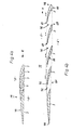
- the device for improving the efficiency of wing-like components consists of a specially designed wing head 1, which is either integrally formed on an overall wing 9 or can be connected to a fuselage wing 12 to form an overall wing 9.
- splitter wings 3 are arranged, which are connected to a wing base 10.
- the gap wings 3 are designed such that the wing edges 4 in the direction of flow X consecutive split wings 3 are each offset in the direction of the pressure zone 6 of the split wing profile.
- the chords 7 of the individual split wings 3 can be arranged generally parallel to each other. However, it is more advantageous to provide a differentiated slope for the individual slotted wings 3.
- the further gap blades 3 following the first gap blades 3 in the inflow direction X are convexly curved with respect to the respective longitudinal axis 8 of the overall blade 9 in such a way that the radially directed flow of the fluid or gas is deflected on the downstream side into a flow directed generally at right angles to the radial flow. It is advantageous to arrange the gap wings 3 extending approximately over the area of the outer third of the length of the overall wing 9.
- the free flow cross-section of the gap 2 between the gap wings 3 is designed such that it increases radially to a maximum at the respective edge 4 of the wing.
- the gap blade or blades 3 at the front in the flow direction X can also be bulged in the flow direction X in the plane of the longitudinal axis 8 of the overall blade 9.
- at least one middle gap leaf 3 is aligned generally coaxially to the longitudinal axis 8 of the overall leaf 9, while the gap leaf 3 following in the outflow direction are bulged toward the pressure zone 6.
- the gap blades 3 are preferably formed with a laminar profile in order to achieve optimal flow conditions. It is possible to form the gap 2 between the gap wings 3 in the form of a nozzle.
- the gap wings 3 are connected to the wing base 10 and integrated in its profile.
- the gap wings 3 and the wing base 10 can be formed in one piece and consist of a high-alloy, possibly high-temperature resistant metal.
- Such wing heads 1 are particularly suitable for gas turbines, in which the wing base 10 is then attached to the rotor of the rotor. They can be provided in the wing base 10 as well as in the gap wings 3 with cooling channels in order to be able to cool the wing heads 1 with a cooling medium. It is also possible for the flow vanes 3 and the wing base 10 to be formed in one piece from a high-temperature-resistant ceramic material for other turbomachines.
- the gap blades 3 and the blade root 10 can consist of a plastic, wood or metal, wherein each gap blade 3 can be connected to the blade root 10 by means of an adhesive connection 16.
- a wing head 1 designed in this way can be connected by means of a coupling or the like to a fuselage wing 12 to form an overall wing 9.
- a recess 14 is formed on the outer end section 13 of the fuselage wing 12, into which the lower section of the wing head 1 is pushed and connected to the fuselage wing 12 by means of an adhesive connection 16.
- a pin 15 is formed, which is guided through the wing base 10 and inserted into the fuselage wing 12.
- Each pin 15 is also with the wing head 1 and the fuselage wing 12 by z. B. bonded connections 16 connected.
- a laminate layer 17 made of plastic or the like is applied, the outer surface of which is adapted to the profile of the gap wings 3, the wing foot 10 and the fuselage wing 12. To increase the strength, it is expedient to form the laminate layer 17 fiber-reinforced.
- a wing head 1 designed in this way makes it possible, as a retrofit component, to improve the performance of existing wind power rotors which are in use. For this purpose, it is only necessary to shorten the existing wings to a fuselage wing 12 and then to place a wing head 1 of the type described above on the end section thereof.
- an expansion wing 19 formed from split wings 3 such that the split wings 3 can be pivoted in the radial plane from an adjacent position (FIG. 4a) into a distant spreading position (FIG. 4b).
- 3 actuators are provided in the wing base 10 for the adjustment of the spreading wings, which can act electrically or hydraulically. So it is z. B. possible to connect each gap leaf 3 with an electric servomotor with a strongly reducing gear. The actuators can be operatively connected to an electronic control device so that either all of the split leaves 3 are pivoted together or only certain selected split leaves 3 are pivoted. It is also possible to design at least one of the gap wings 3 to be rotatable about its longitudinal axis.
- the diagram according to FIG. 5 illustrates the advantages of the expansion wing 19.
- This diagram shows a test result in which a one-piece basic profile and an expansion wing 19 consisting of five split wings 3 were measured at the same inflow speeds.
- the profile envelope 73 of the expansion wing 19 corresponds to the basic profile. It can be clearly seen that with the same drag coefficients cd, the lateral force coefficients cc of the expansion wing 19 are higher than in the basic profile.
- each propeller blade 20 is designed like an expansion blade and has four split blades 3. These split wings 3 are profiled. For their formation, three radially arranged in each propeller blade 20 extending convex column 2. The columns 2 extend approximately from the propeller hub 33 to the edge of the wing 4. The profiling of the gap blades 3 is such that the individual gap blades 3 successive in the direction of rotation one each propeller blade 20 to the wing edge 4 and offset from each other in the outflow direction.
- the front gap blades 3 are generally radially aligned with the propeller hub 33.
- the middle gap wings 3 and the rear gap wings 3 are arched to the pressure zone.
- the gap wings 3 are each offset from one another.
- the front gap blades 3 are arranged in a radial normal plane which is oriented at an oblique angle to the longitudinal axis 23 of the propeller to the pressure zone.
- the surfaces of the gap wings 3 around which the fluid flows are approximately the same size.
- the middle gap blades 3 extend generally radially to the propeller hub 33, while the front gap blade 3 is pre-curved to the center gap blades 3 and the rear gap blade 3 is curved back to the center gap blades 3.
- the gap edges 24, 25 of the mutually facing edge sides of the gap blades 3 can be skewed at an angle to the propeller plane, but generally parallel to one another. As a result, the profile curvature of the individual gap wings 3 is reinforced.
- the upstream and downstream edges 26, 27 can also be sharpened at an oblique angle to the propeller plane. It is particularly distributed to make the column 2 nozzle-shaped and to provide the split wings 3 with a laminar profile.
- propeller 21 of dividing each propeller blade 20 into different gap blades 3 is not limited to propellers with regard to its application. Such propellers can also be used in water turbines designed as propeller turbines and in steam or gas turbines.
- Spreading wings 19 with split wings 3 in the form of split wing bundles 66 can also be used for other purposes on wind and motor-driven sea vehicles, such as. B. as stabilizing fins and / or trim tabs and / or deep rudders. In these cases, the maneuverability of the vessel in question is improved. It is also possible that the split wing bundle 66 on both sides on a keel 61 for z. B. to arrange sea-going sailing yachts.
- the keel of a sailing yacht serves as ballast and acts like a vertical wing to generate a hydrodynamic side force. This partially compensates for the lateral forces exerted by the sails.
- Ballast in yachts is usually made of lead and can make up between 70 and 80% of the total boat weight.
- the keel primarily has the task, the focus of the yacht to be determined. The deeper it is, the more stable the boat is.
- a keel has a significant influence on four of the five types of resistance encountered by a moving hull.
- the keel Depending on the shape, it creates a form resistance through flow pressure due to turbulence. Furthermore, the keel has a very large wetted surface and is short along the direction of flow, so that it contributes disproportionately to the frictional resistance. Third, the volume of the keel, which is only one to two meters below the surface of the water, increases the total wave-generating resistance of the yacht. Fourth, the keel shape significantly affects the size of the induced drag caused by the side force. The induced drag makes the largest contribution of the keel to the total drag and decreases as the span of the buoyancy system is increased. The range can only be increased to a limited extent for various reasons.
- 11 to 17 show the arrangement of wings 62, 63 designed as a split wing bundle 66 on a keel 61.
- the keel 61 shown schematically in a side view in FIG. 11 can have a hydraulic shape adapted to the area of application of the yacht.
- wings 62, 63 are arranged on both sides in the area of the rear section thereof, on which split wings 3 are formed by gaps 2 extending to the wing edge 4.
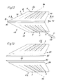
- FIGS. 12 and 13 show the top view of the wings 62, 63 to be attached to a keel 61 on both sides.
- Each wing 62, 63 forms a split wing bundle 66 which is formed by the gaps 2 extending to the wing edge 4.
- the longitudinal slots 74 are aligned in a straight line but at an oblique angle to the inflow direction x.
- the leading edge 78 of the first splitting wing 3 in the inflow direction x and the trailing edge 79 of the last splitting wing 3 in the inflow direction x are also oriented at an oblique angle to the inflow direction x.
- the wing root 10 of each wing 62, 63 consists of a one-piece foot section 84 of the respective split wing bundle 66 and a fitting piece 85 which can be connected to the foot section 84.
- the fitting pieces 85 are adapted to the profile of the foot sections 84 and can be positively connected to the keel 61.
- the adapters 85 it is possible to fasten split wing bundles 66 of wings 62, 63 to keels 61 with different profiles.
- the surfaces 55 can be flat as shown, but will generally have a spatially profiled shape due to the profiling of the keel 61.
- the gap wings 3 are rounded in the area of the wing edge 4 on the inflow side, as is shown in FIGS. 12 and 13 by the enlarged detail view.
- the overflow-side inflow edges 78, 68 of the gap vanes 3 successive in the inflow direction x are arranged horizontally offset in relation to the vacuum-side outflow edges 69 of the split vanes 3 in the inflow direction x, so that in the region of each gap inlet 81 the pressure-side inflow edge 68 of a split wing 3 the vacuum egg term trailing edge 69 of the other gap wing 3 overlaps.
- the trailing edges 69 are formed with sharp edges, as has already been described for FIGS. 4a and 4b.
- the gaps 2 are nozzle-shaped, the direction of flow extending from the pressure zone 6 to the vacuum zone 5.
- the gap wings 3 are shaped such that they are located within the profile envelope 73 defined by the wing root 10 of each gap wing bundle 66. This avoids a disturbance of the flow in the area of the pressure zone 6 or the vacuum zone 5. Relative to the vacuum zone 5, the split vanes 3 can have different pitches so that the vanes 62, 63 can be hydrodynamically optimized depending on their geometry. Furthermore, the profile envelope 73 has an overall slope to the horizontal 76.
- the pressure-side surfaces 80 have a convexly curved surface section 82 adjoining the leading edge 78, 68, to which a concavely curved surface section 83 extending up to the respective trailing edge 69 adjoins.
- This configuration of the gap cross section leads a portion of the water flowing along the underside of the wing 62, 63 to the top of the wing 62, 63, and prevents energy from prematurely swirling the water flowing past the top of the wing 62, 63.
- the cross-sectional configuration of the split wings 3 of the wings 62, 63 is thus corresponding to that of the split wings 3 of the expanding wing 19 according to FIG. 4b.
- the angles of attack of the blades 62, 63 can be adjusted simultaneously or independently of one another.
- Control units 86, 87 located on board the ship are used for this purpose, each of which is assigned to one of the wings 62, 63.
- the angle of attack of the wings 62, 63 can be adjusted depending on the operating state of the yacht carrying the keel 61.
- the setting of the angle of attack can be made particularly advantageously by means of hydraulic servomotors 88, their position is electrohydraulically adjustable by means of the control units 86, 87.
- the actuators 88 can be designed, for example, as rotary piston motors or as two-chamber swivel lever drives 97.
- each fitting 85 is provided in each fitting 85 as the servomotor 88, the position of which can be adjusted hydraulically by means of the control units 86, 87.
- Each rotary piston engine is connected by a pin 89 to the split wing bundle 66 of the wing 62, 63 in question.
- the pins 89 are supported on both sides of the rotary piston motors by means of bearings 90.
- each pin 89 is secured in the area of the adapter 85 by means of a screw connection 96.
- the fitting pieces 85 are connected to the keel 61 by means of indicated screw connections 95.
- Each rotary piston motor has a position sensor 91 which is connected to the associated control unit 86, 87 by means of a measured value line 92.
- This enables the person operating the control units 86, 87 to always be able to monitor and, if necessary, correct the angle of attack of the blades 62, 63.
- the measured value lines 92 and the pressure oil lines 93, 94 required for the operation of the actuators 88 are expediently led through the keel 61 into the ship's hull.
- an empty tube 54 can be provided in the keel 61.
- the control units 86, 87 act on an electromagnetic control unit 51, which is connected to a multi-way valve 49. This is preferably arranged on the hull-side end section of the keel 61. From the multi-way valve 49, pressure oil is metered from a pressure oil supply device 50 and supplied to the rotary lobe motors in a controlled manner.
- FIGS. 17a to 17c show a further embodiment of a hydraulic servomotor 88 which is designed as a two-chamber swivel lever drive 97.
- This two-chamber swivel lever drive 97 is double-acting and can be arranged in the keel 61, one drive part 98 being connected to the pin 89 of the one split-wing bundle 66 and the other drive part 99 being connected to the pin 89 of the other split-wing bundle 66.
- the pins 89 are guided through openings 40 formed in the fitting pieces 85 as bearings 90.
- the bearings 90 can be designed as plain bearings.
- Each drive part 98, 99 has two chambers 43, 44; 45, 46, which by means of a pressure oil line 93, 94; 47, 48 are connected to an electrohydraulic multi-way valve 49.
- a position sensor 91 is also provided on each drive part 98, 99 and is connected to the associated control unit 86, 87 by means of a measured value line 92. Even when using a two-chamber swivel lever drive 97, the pressure oil lines 93, 94; 47, 48 and the measured value lines 92 are guided through the keel 61 in an empty tube 54.
- the electrohydraulic multi-way valve 49 can be arranged on the hull-side end section of the keel 61 and can be actuated by an electromagnetic control unit 51 connected to the control units 86, 87, as has already been explained with reference to FIG. 16.
- the two-chamber swivel lever drive 97 consists of a housing 56 in which the chambers 43, 44; 45, 46 and the pivot levers 41, 42 are arranged.
- the housing 56 is advantageously inserted directly into the keel 61 and fastened by means of screws 59.
- a fitting 85 is then arranged on each side of the housing 56 and connected to the keel 61 by means of screw connections 95.
- a partition 57 is formed in the middle of the housing 56, through which the chambers 43, 44; 45, 46 are formed.
- Pins 58 which are connected to pins 89, are supported on both sides of partition 57.
- the pivot levers 41, 42 are connected in a rotationally fixed manner to the associated pins 89 of the split-wing bundle 66.
- This version of the two-chamber swivel lever drive 97 enables a particularly compact design with simultaneous transmission of large actuating forces and is therefore particularly suitable for adjusting the angle of attack of vanes 62, 63.
Abstract
Die Erfindung betrifft eine als Spreizflügel 19 ausgebildete profilierte Einrichtung zur Verbesserung des Wirkungsgrads bei von einem Gas oder einem Fluid umströmten flügelartigen Bauelementen wie Tragflügel, Schaufeln von Strömungsmaschinen, Propeller, Kiele von Schiffen oder dergleichen. Der Spreizflügel 19 besteht aus einem Bündel profilierter Spaltflügel 3 mit Laminarprofil, die durch im Abstand von der Wurzel des Spreizflügels 19 ausgebildete radial verlaufende Spalte gebildet werden. Die Flügelränder 4 der in Anströmrichtung X aufeinanderfolgenden Spaltflügel sind zueinander jeweils in Richtung der Druckzone 6 versetzt ausgebildet. Die Spalte 2 zwischen den Flügelrändern 4 sind düsenförmig ausgebildet mit einer sich von der Druckzone 6 zur Unterdruckzone 5 erstreckenden Strömungsrichtung. Die Spaltflügel 3 befinden sich innerhalb der durch den Flügelfuß des Spaltflügelbündels vorgegebenen Profilumhüllenden 73.The invention relates to a profiled device designed as an expansion wing 19 for improving the efficiency of wing-like components such as hydrofoils, blades of turbomachines, propellers, keels of ships or the like, which are surrounded by a gas or a fluid. The spreading wing 19 consists of a bundle of profiled split wings 3 with laminar profile, which are formed by radially extending gaps formed at a distance from the root of the spreading wing 19. The wing edges 4 of the gap wings which follow one another in the inflow direction X are each offset with respect to one another in the direction of the pressure zone 6. The gaps 2 between the wing edges 4 are nozzle-shaped with a flow direction extending from the pressure zone 6 to the vacuum zone 5. The gap wings 3 are located within the profile envelope 73 specified by the wing base of the gap wing bundle.
Description
Die Erfindung betrifft eine flügelartige profilierte Einrichtung, die von einem Gas oder einem Fluid umströmt wird und zur Verbesserung des Wirkungsgrades streifenförmige profilierte Flügel aufweist, zwischen denen zur Verschiebung der Strömungsabrißzone jeweils ein sich zum Rand der streifenförmigen Flügel zu einer maximalen Breite erweiternder Spalt angeordnet ist.The invention relates to a wing-like profiled device which is flowed around by a gas or a fluid and has strip-shaped profiled wings for improving the efficiency, between which a gap widening to the edge of the strip-shaped wings to a maximum width is arranged in order to shift the stall zone.
Eine derartige Einrichtung ist durch die DE-PS 31 05 183 bekannt. Bei dieser Einrichtung besteht jedoch der Nachteil, daß bei größeren Baulängen der streifenförmigen Flügel diese aufgrund ihrer Elastizität schwingen können, was die Strömung des Fluids oder Gases beeinträchtigen kann. Zur Vermeidung dieser Nachteile sind daher außerordentlich hochwertige Werkstoffe erforderlich, wodurch die Herstellungskosten dieser bekannten Einrichtung extrem erhöht werden. Außerdem hat es sich gezeigt, daß mit dieser bekannten Einrichtung die Strömungsverluste durch Verminderung des Einflusses von Strömungswirbeln zwar verringert werden, die Steigerung des Wirkungsgrades und damit der Energieausnutzung aber doch begrenzt ist.Such a device is known from DE-PS 31 05 183. With this device, however, there is the disadvantage that with longer lengths of the strip-shaped wings they can vibrate due to their elasticity, which can impair the flow of the fluid or gas. To avoid these disadvantages, extremely high-quality materials are therefore required, which extremely increases the manufacturing costs of this known device. In addition, it has been shown that with this known device the flow losses are reduced by reducing the influence of flow eddies, but the increase in efficiency and thus the energy utilization is nevertheless limited.
Die Aufgabe der Erfindung besteht darin, die Einrichtung der eingangs genannten Art so zu verbessern, daß bei vereinfachter Herstellung der Wirkungsgrad optimiert und ein universeller Einsatzbereich bei von Fluiden oder Gasen umströmten Bauteilen erzielt wird.The object of the invention is to improve the device of the type mentioned in such a way that, with simplified manufacture, the efficiency is optimized and a universal area of application is achieved in the case of components flowed around by fluids or gases.
Erfindungsgem. erfolgt die Lösung der Aufgabe dadurch, daß die flügelartige Einrichtung durch im Abstand von der Wurzel angeordnete radial verlaufende Spalte spreizflügelartig als Bündel profilierter Spaltflügel mit Laminarprofil ausgebildet ist, die derart zueinander angeordnet sind, daß die Flügelränder der in Anströmrichtung aufeinander folgenden Spaltflügel zueinander jeweils in Richtung der Druckzone des Spaltflügelsprofils versetzt ausgebildet sind. Gemäß der Erfindung ist diese Einrichtung universal an von Fluiden oder Gasen umströmten Bauteilen einsetzbar, so insbesondere zur Ausbildung von Tragflügeln, Propellerflügeln von Schraubenpropellern und Hubschrauber-Rotoren, Flügeln an Schiffsrümpfen und Schiffskielen u. dgl.According to the invention. the problem is solved in that the wing-like device is designed as a bundle of profiled split wings with a laminar profile, which are arranged in such a way that the wing edges of the split wings which follow one another in the upstream direction are in each case in the direction of one another by radially extending gaps arranged at a distance from the root the pressure zone of the split wing profile are offset. According to the invention, this device can be used universally on components around which fluids or gases flow, so in particular for the formation of wings, propeller wings of screw propellers and helicopter rotors, wings on hulls and keels and the like. the like
Weitere Merkmale der Erfindung werden in den abhängigen Ansprüchen beschrieben und nachstehend am Beispiel der in den Zeichnungen dargestellten Einrichtungen näher erläutert. Es zeigt
- Fig. 1 eine Ausführung eines erfindungsgemäßen Spreizflügels in einer Ansicht von vorn,
- Fig. 2 den Flügelfuß des Spreizflügels nach Fig. 1 in einer schematischen perspektivischen Ansicht,
- Fig. 3 den Spreizflügel nach Fig. 1 in einer Seitenansicht,
- Fig. 4a eine weitere Ausführungsform eines Spreizflügels in einer Queransicht im Schnitt mit aneinanderliegendem Spaltflügeln,
- Fig. 4b den Spreizflügel nach Fig. 4a mit auseinandergeschwenkten Spaltflügeln in einer Queransicht im Schnitt,
- Fig. 5 ein Diagramm über Vergleichsmessungen eines Normalprofils und eines Spreizflügels,
- Fig. 6 einen Schraubenpropeller in einer perspektivischen Ansicht,
- Fig. 7 und 8 den Strömungsverlauf an einem Normalflügel und an einem Spreizflügel eines Schraubenpropellers in schematischen Ansichten,
- Fig. 9 einen Propellerflügel des Schraubenpropellers nach Fig. 6 in einer schematischen Seitenansicht,
- Fig. 10 die Querschnitte der Spaltflügel eines Propellerflügels nach Fig. 9 in einer schematischen Ansicht,
- Fig. 11 einen Kiel mit einer erfindungsgemäßen Einrichtung in der Seitenansicht,
- Fig. 12 ein Flügelpaar für einen Kiel in einer schematischen Draufsicht,
- Fig. 13 das Flügelpaar nach Fig. 12 in einer Draufsicht in einer Explosionsdarstellung,
- Fig. 14 eine Ansicht auf den Flügelrand,
- Fig. 15 den Flügel nach Fig. 13 in einer Queransicht im Schnitt A-A,
- Fig. 16 eine schematische Ansicht auf einen Kiel mit Flügeln in Richtung B-B mit einer Flügelverstelleinrichtung,
- Fig. 17a bis 17c eine weitere Ausbildung einer Flügelverstelleinrichtung in einer Seitenansicht, Queransicht und Draufsicht.
- 1 shows an embodiment of an expansion wing according to the invention in a view from the front,
- 2 shows the wing base of the expansion wing according to FIG. 1 in a schematic perspective view,
- 3 shows the spreading wing according to FIG. 1 in a side view,
- 4a shows a further embodiment of an expansion wing in a transverse view in section with the split wings lying against one another,
- 4b the spreading wing according to FIG. 4a with the split wings pivoted apart in a transverse view in section,
- 5 shows a diagram of comparative measurements of a normal profile and an expansion wing,
- 6 a screw propeller in a perspective view,
- 7 and 8 the flow pattern on a normal wing and on an expansion wing of a screw propeller in schematic views,
- 9 shows a propeller wing of the screw propeller according to FIG. 6 in a schematic side view,
- 10 is a schematic view of the cross sections of the gap blades of a propeller blade according to FIG. 9,
- 11 is a keel with a device according to the invention in side view,
- 12 shows a pair of wings for a keel in a schematic plan view,
- 13 shows the wing pair according to FIG. 12 in a plan view in an exploded view,
- 14 is a view of the wing edge,
- 15 shows the wing according to FIG. 13 in a transverse view in section AA,
- 16 is a schematic view of a keel with wings in the direction BB with a wing adjustment device,
- 17a to 17c show a further embodiment of a wing adjustment device in a side view, transverse view and top view.
Wie in Fig. 1 dargestellt, besteht die Einrichtung zur Verbesserung des Wirkungsgrades von flügelartigen Bauelementen aus einem besonders ausgebildeten Flügelkopf 1, der entweder einstückig an einem Gesamtflügel 9 ausgebildet ist oder aber mit einem Rumpfflügel 12 zu einem Gesamtflügel 9 verbunden werden kann. An dem Flügelkopf 1 sind spreizflügelartig Spaltflügel 3 angeordnet, die mit einem Flügelfuß 10 verbunden sind. Die Spaltflügel 3 sind derart ausgebildet, daß die Flügelränder 4 der in Anströmrichtung X aufeinander folgenden Spaltflügel 3 zueinander jeweils in Richtung der Druckzone 6 des Spaltflügelprofils versetzt sind. Die Profilsehnen 7 der einzelnen Spaltflügel 3 können hierbei allgemein parallel zueinander angeordnet sein. Vorteilhafter ist es jedoch, für die einzelnen Spaltflügel 3 eine differenzierte Steigung vorzusehen. Die auf den in Anströmrichtung X ersten Spaltflügel 3 folgenden weiteren Spaltflügel 3 sind bezogen auf die jeweilige Längsachse 8 des Gesamtflügels 9 derart konvex gekrümmt ausgebildet, daß die radial gerichtete Strömung des Fluids oder Gases abstromseitig in eine allgemein rechtwinklig zur radialen Strömung gerichtete Strömung umgelenkt wird. Vorteilhaft ist es, die Spaltflügel 3 etwa über den Bereich des äußeren Drittels der Länge des Gesamtflügels 9 sich erstreckend anzuordnen. Hierbei ist der freie Durchströmquerschnitt der Spalte 2 zwischen den Spaltflügeln 3 so ausgebildet, daß er sich radial zu einem Maximum am jeweiligen Flügelrand 4 vergrößert.As shown in Fig. 1, the device for improving the efficiency of wing-like components consists of a specially designed
Es ist möglich, den in Anströmrichtung X vorderen Spaltflügel 3 allgemein koaxial zur Längsachse 8 des Gesamtflügels 9 auszurichten und die folgenden Spaltflügel 3 zur Druckzone 6 vorgewölbt auszubilden. Bei besonderen Betriebsbedingungen können auch der oder die in Anströmrichtung X vorderen Spaltflügel 3 in der Ebene der Längsachse 8 des Gesamtflügels 9 in Anströmrichtung X vorgewölbt sein. In diesem Fall ist mindestens ein mittlerer Spaltflügel 3 allgemein koaxial zur Längsachse 8 des Gesamtflügels 9 ausgerichtet, während die in Abströmrichtung folgenden Spaltflügel 3 zur Druckzone 6 vorgewölbt sind. Vorzugsweise werden die Spaltflügel 3 mit einem Laminarprofil ausgebildet, um optimale Strömungsverhältnisse zu erzielen. Möglich ist es, die Spalte 2 zwischen den Spaltflügeln 3 düsenförmig auszubilden.It is possible to align the front splitting
Wie in Fig. 2 angedeutet, sind die Spaltflügel 3 mit dem Flügelfuß 10 verbunden und in dessen Profil integriert. Die Spaltflügel 3 und der Flügelfuß 10 können einstückig ausgebildet sein und aus einem hochlegierten ggf. hochtemperaturbeständigen Metall bestehen. Derartige Flügelköpfe 1 eignen sich insbesondere für Gasturbinen, bei denen dann der Flügelfuß 10 auf dem Läufer des Rotors befestigt wird. Sie können sowohl im Flügelfuß 10 wie auch in den Spaltflügeln 3 mit Kühlkanälen versehen sein, um die Flügelköpfe 1 mit einem Kühlmedium kühlen zu können. Es ist auch möglich, für andere Strömungsmaschinen die Spaltflügel 3 und den Flügelfuß 10 einstückig aus einem hochtemperaturbeständigen keramischen Werkstoff auszubilden.As indicated in Fig. 2, the
Insbesondere zur Verwendung bei Windkraftrotoren können die Spaltflügel 3 und der Flügelfuß 10 aus einem Kunststoff, Holz oder Metall bestehen, wobei jeder Spaltflügel 3 mittels einer Klebverbindung 16 mit dem Flügelfuß 10 verbunden sein kann. Ein derart ausgebildeter Flügelkopf 1 kann mittels einer Kupplung od. dgl. mit einem Rumpfflügel 12 zu einem Gesamtflügel 9 verbunden werden.In particular for use in wind power rotors, the
In den Fig. 3 ist eine besondere Ausbildung einer Kupplung dargestellt. An dem äußeren Endabschnitt 13 des Rumpfflügels 12 ist eine Ausnehmung 14 ausgebildet, in die der untere Abschnitt des Flügelkopfes 1 geschoben und mittels einer Klebverbindung 16 mit dem Rumpfflügel 12 verbunden ist. An jedem Spaltflügel 3 ist ein Zapfen 15 ausgebildet, der durch den Flügelfuß 10 geführt und in den Rumpfflügel 12 gesteckt ist. Jeder Zapfen 15 ist mit dem Flügelkopf 1 und dem Rumpfflügel 12 ebenfalls durch z. B. Klebverbindungen 16 verbunden. Im Bereich der Verbindungsabschnitte der Spaltflügel 3 mit dem Flügelfuß 10 und des Flügelkopfes 1 mit dem Rumpfflügel 12 ist eine Laminatschicht 17 aus Kunststoff od. dgl. aufgetragen, deren äußere Oberfläche dem Profil der Spaltflügel 3, des Flügelfußes 10 und des Rumpfflügels 12 angepaßt ist. Zur Erhöhung der Festigkeit ist es zweckmäßig, die Laminatschicht 17 faserverstärkt auszubilden.3 shows a special design of a clutch. A
Ein derart ausgebildeter Flügelkopf 1 ermöglicht es, als Nachrüstbauteil bereits bestehende und im Einsatz befindliche Windkraftrotoren in ihrer Leistung zu verbessern. Hierzu ist es lediglich erforderlich, die vorhandenen Flügel zu einem Rumpfflügel 12 zu verkürzen und auf dessen Endabschnitt dann jeweils einen Flügelkopf 1 der oben beschriebenen Art aufzusetzen.A
Es ist auch möglich, einen aus Spaltflügeln 3 gebildeten Spreizflügel 19 so auszubilden, daß die Spaltflügel 3 in der radialen Ebene von einer aneinanderliegenden Stellung (Fig. 4a) in eine distanzierte Spreizstellung (Fig. 4b) verschwenkbar sind. In diesem Fall sind in dem Flügelfuß 10 für die Verstellung der Spreizflügel 3 Stellantriebe vorgesehen, die elektrisch oder hydraulisch wirken können. So ist es z. B. möglich, jeden Spaltflügel 3 mit einem elektrischen Stellmotor mit einem stark untersetzenden Getriebe zu verbinden. Die Stellantriebe können so mit einer elektronischen Regeleinrichtung in Wirkverbindung stehen, daß entweder alle Spaltflügel 3 gemeinsam oder aber nur bestimmte ausgewählte Spaltflügel 3 verschwenkt werden. Es ist auch möglich, mindestens einen der Spaltflügel 3 um seine Längsachse verdrehbar auszubilden. Hierdurch kann gezielt eine Störung der Umströmung des Spreizflügels 19 bewirkt werden, wenn es die jeweiligen Betriebsbedingungen erfordern. Wie Fig. 4a verdeutlicht, kann bei entsprechender Profilierung der Spaltflügel 3 nach deren Aufeinanderschwenken ein Hochleistungsprofil erzeugt werden, daß insbesondere für höhere Anströmgeschwindigkeiten geeignet ist. Bei geringen Anströmgeschwindigkeiten wird der fünfgliedrige Spreizflügel 19 in eine Stellung wie z. B. in Fig. 4b dargestellt aufgefächert. Die Spaltflügel 3 befinden sich stets innerhalb einer durch die Ausbildung des Spreizflügels 19 vorgegebenen Profilumhüllenden 73 (Fig. 4a und 4b). Im Bereich der unterdruckseitigen Spaltendabschnitte 75 sind die Abströmkanten 69 der Spaltflügel 3 scharfkantig ausgebildet. Durch die Spreizung der Spaltflügel 3 wird ohne merkliche Erhöhung des induzierten Widerstandes eine erhebliche Verbesserung des Auftriebs erzielt. Unter Einhal tung der Profilgeometrie eines Laminarprofils beeinflußt die Scherströmung den Wirbelzopf so, daß die Wirbelschleppe verkürzt und der Wirkungsgrad entscheidend verbessert wird. Bei Möglichkeit der Einzelsteuerung der Spaltflügel 3 ist es gewährleistet, den jeweiligen Energieumsatz maximal zu nutzen.It is also possible to form an
Das Diagramm nach Fig. 5 verdeutlicht die Vorteile des Spreizflügels 19. Dieses Diagramm zeigt ein Versuchsergebnis, bei dem bei gleichen Anströmgeschwindigkeiten ein einstückiges Basisprofil und ein aus funf Spaltflügeln 3 bestehender Spreizflügel 19 vermessen wurde. Die Profilumhüllende 73 des Spreizflügels 19 entspricht dem Basisprofil. Es ist deutlich erkennbar, daß bei gleichen Widerstandsbeiwerten cd die Querkraftbeiwerte cc des Spreizflügels 19 höher sind als beim Basisprofil.The diagram according to FIG. 5 illustrates the advantages of the
In Fig. 6 ist ein Propeller 21 dargestellt, der drei Propellerflügel 20 aufweist. Jeder Propellerflügel 20 ist spreizflügelartig ausgebildet und weist vier Spaltflügel 3 auf. Diese Spaltflügel 3 sind profiliert. Zu ihrer Ausbildung erstrecken sich drei radial angeordnete in jedem Propellerflügel 20 konvex verlaufende Spalte 2. Die Spalten 2 erstrecken sich etwa von der Propellernabe 33 bis zum Flügelrand 4. Die Profilierung der Spaltflügel 3 ist so, daß die einzelnen in Umdrehungsrichtung aufeinander folgenden Spaltflügel 3 eines jeden Propellerflügels 20 zum Flügelrand 4 und in Abströmrichtung zueinander versetzt ausgebildet sind.6 shows a
Die vorderen Spaltflügel 3 sind allgemein radial zur Propellernabe 33 ausgerichtet. Die mittleren Spaltflügel 3 und die hinteren Spaltflügel 3 sind zur Druckzone vorgewölbt. Hierbei sind die Spaltflügel 3 jeweils versetzt zueinander ausgebildet. Die vorderen Spaltflügel 3 sind in einer radialen Normalebene angeordnet, die schiefwinklig zur Propellerlängsachse 23 zur Druckzone ausgerichtet ist.The
Die vom Fluid umströmten Flächen der Spaltflügel 3 sind etwa gleich groß. Die mittleren Spaltflügel 3 erstrecken sich allgemein radial zur Propellernabe 33, während der vordere Spaltflügel 3 zu den mittleren Spaltflügeln 3 vorgekrümmt und der hintere Spaltflügel 3 zu den mittleren Spaltflügeln 3 zurückgekrümmt ist.The surfaces of the
Die Spaltkanten 24, 25 der einander zugewandten Randseiten der Spaltflügel 3 können zur Propellerebene schiefwinklig, zueinander aber allgemein parallel angeschärft sein. Hierdurch wird die Profilwölbung der einzelnen Spaltflügel 3 verstärkt.The gap edges 24, 25 of the mutually facing edge sides of the
Die an- und abströmseitigen Randseiten 26, 27 können ebenfalls zur Propellerebene schiefwinklig angeschärft sein. Besonders verteilhaft ist es, die Spalte 2 düsenförmig auszubilden und die Spaltflügel 3 mit einem Laminarprofil zu versehen.The upstream and
Durch die Ausbildung der Spalte 2 in den einzelnen Propellerflügeln 20 ist es möglich, die bei konventionellen Schiffsschrauben abströmseitig auftretenden Unterdruckzonen zu verringern. Turbulenzen sowie die Gefahr des Eintritts von Kavitation werden vermindert. In Fig. 7 und 8 ist der Unterschied des Strömungsverlaufs an einem üblichen einstückigen Propellerflügel 20 und an einem in Spaltflügel 3 aufgeteilten weiteren Propellerflügel 20 verdeutlicht. Während bei dem spreizflügelartigen Propellerflügel 20 das Geschwindigkeitsprofil über die Flügeltiefe gleich bleibt, erfolgt bei dem Normalprofil durch Wirbelbildung eine teilweise Umkehr der Strömungsrichtung, so daß der induzierte Widerstand vergrößert wird. Es ist daher möglich, den Propeller 21 mit einer höheren Drehzahl zu betreiben als es bei Propellern vergleichbarer Größe, jedoch ohne Spaltflügel 3 möglich ist. Durch die optimierte Übertragung der von der Antriebswelle auf den Propeller abgegebenen Energie durch Bündelung der beschleunigten Fluidmasse koaxial zur Propellerlängsachse 23 wird der Wirkungsgrad des Propellers 21 gegenuber bekannten Ausführungsformen erheblich erhöht. Hierzu trägt auch bei, daß das Profilskelett eines Propellerflügels 20 im Bereich des Flügelfußes 10 eine maximale Wölbung aufweist, während die Profilskelette der Spaltflügel 3 am Flügelrand 4 gestreckt ausgebildet sind. Fig. 9 zeigt einen Propellerflügel 20 in einer Seitenansicht und verdeutlicht die gekrümmte Ausbildung der Spaltflügel 3 und der Spalte 2. Die Überdeckungen der Spaltkanten 24, 25 einander benachbarter Spaltflügel 3 sind angedeutet. Fig. 10 zeigt den Aufriß der Profilquerschnitte der Spaltflügel 3 des Propellerflügels 20 nach Fig. 9.By forming the
Das dem Propeller 21 zugrundeliegende Prinzip der Aufteilung eines jeden Propellerflügels 20 in verschiedene Spaltflügel 3 ist hinsichtlich seiner Anwendung nicht auf Schiffsschrauben beschränkt. Derartige Propeller können auch bei als Propellerturbinen ausgebildeten Wasserturbinen sowie bei Dampf- oder Gasturbinen Anwendung finden.The principle underlying the
Spreizflügel 19 mit Spaltflügeln 3 in Form von Spaltflügelbündeln 66 können auch für andere Zwecke an wind- und motorbetriebenen Seefahrzeugen verwendet werden, so z. B. als Stabilisierungsflossen und/oder Trimmflossen und/oder Tiefenruder. In diesen Fällen wird die Manövrierfähigkeit des betreffenden Seefahrzeugs verbessert. Es ist auch möglich, die Spaltflügelbündel 66 beidseitig an einem Kiel 61 für z. B. hochseefähige Segeljachten anzuordnen.Spreading
Der Kiel einer Segeljacht dient als Ballast und wirkt wie ein vertikaler Tragflügel zur Erzeugung einer hydrodynamischen Seitenkraft. Diese gleicht die von den Segeln ausgehenden seitlichen Kräfte zum Teil aus. Als Ballast stabilisiert der Kiel den Rumpf gegen das Krängungsmoment der auf die Segel wirkenden Kräfte. Üblicherweise besteht der Ballast bei Jachten aus Blei und kann zwischen 70 und 80% des gesamten Bootsgewichts ausmachen. Der Kiel hat als Ballast vor allem die Aufgabe, den Schwerpunkt der Jacht festzulegen. Je tiefer dieser ist, um so stabiler ist das Boot. Als Tragflügel hat ein Kiel maßgeblichen Einfluß auf vier der fünf Widerstandsarten, denen ein bewegter Schiffskörper begegnet. Abhängig von der jeweiligen Formgebung erzeugt er einen Formwiderstand durch Strömungsdruck infolge Turbulenzen. Ferner hat der Kiel eine recht große benetzte Oberfläche und ist längs der Strömungsrichtung kurz, so daß er überproportional zum Reibungswiderstand beiträgt. Drittens vermehrt das Volumen des Kiels, der sich nur ein bis zwei Meter unter der Oberfläche des Wassers befindet, den gesamten wellenerzeugenden Widerstand der Jacht. Viertens beeinflußt die Kielgestalt wesentlich die Größe des induzierten Widerstandes, der durch die Seitenkraft entsteht. Der induzierte Widerstand macht den größten Beitrag des Kiels zum Gesamtwiderstand aus und nimmt ab, wenn die Spannweite des Auftriebssystems vergrößert wird. Eine Vergrößerung der Spannweite ist aus verschiedenen Gründen nur begrenzt möglich. Es ist daher bereits vorgeschlagen worden, den Kiel im Bereich des unteren Endabschnitts seitlich mit kleinen Flügeln zu versehen, wobei die Flügel zur Horizontalen in einem bestimmten Winkel abwärts geneigt angeordnet werden. Durch derartige Flügel wird der induzierte Widerstand des Kiels vermindert. Bei einem ausgeführten Kiel mit Flügeln ist ferner an diesen noch ein Trimmruder vorgesehen worden, das vom Bootsinnern her bedienbar istThe keel of a sailing yacht serves as ballast and acts like a vertical wing to generate a hydrodynamic side force. This partially compensates for the lateral forces exerted by the sails. As a ballast, the keel stabilizes the hull against the heeling moment of the forces acting on the sails. Ballast in yachts is usually made of lead and can make up between 70 and 80% of the total boat weight. As a ballast, the keel primarily has the task, the focus of the yacht to be determined. The deeper it is, the more stable the boat is. As a wing, a keel has a significant influence on four of the five types of resistance encountered by a moving hull. Depending on the shape, it creates a form resistance through flow pressure due to turbulence. Furthermore, the keel has a very large wetted surface and is short along the direction of flow, so that it contributes disproportionately to the frictional resistance. Third, the volume of the keel, which is only one to two meters below the surface of the water, increases the total wave-generating resistance of the yacht. Fourth, the keel shape significantly affects the size of the induced drag caused by the side force. The induced drag makes the largest contribution of the keel to the total drag and decreases as the span of the buoyancy system is increased. The range can only be increased to a limited extent for various reasons. It has therefore already been proposed to provide the keel with small wings laterally in the region of the lower end section, the wings being arranged inclined downwards at a certain angle to the horizontal. The induced resistance of the keel is reduced by such wings. In the case of a keel with wings, a trim rudder has also been provided, which can be operated from inside the boat
In den Fig. 11 bis 17 ist die Anordnung von als Spaltflügelbündel 66 ausgebildeten Flügeln 62, 63 an einem Kiel 61 dargestellt.11 to 17 show the arrangement of
Der in Fig. 11 schematisch in einer Seitenansicht dargestellte Kiel 61 kann eine dem Einsatzgebiet der Jacht angepaßte hydraulische Form haben. An der Unterseite des Kiels 61 sind im Bereich von dessen hinterem Abschnitt beidseitig Flügel 62,63 angeordnet, an denen durch sich bis zum Flügelrand 4 erstreckende Spalte 2 Spaltflügel 3 ausgebildet sind.The
In den Figuren 12 und 13 sind die beidseitig an einem Kiel 61 anzubringenden Flügel 62, 63 in der Draufsicht dargestellt. Jeder Flügel 62, 63 bildet ein Spaltflügelbündel 66, das durch die sich bis zum Flügelrand 4 erstreckenden Spalte 2 gebildet wird. Die Spaltlängsachsen 74 sind geradlinig aber schiefwinklig zur Anströmrichtung x ausgerichtet. Die Anströmkante 78 des in Anströmrichtung x ersten Spaltflügels 3 sowie die Abströmkante 79 des in Anströmrichtung x letzten Spaltfügels 3 sind ebenfalls schiefwinklig zur Anströmrichtung x ausgerichtet.FIGS. 12 and 13 show the top view of the
Der Flügelfuß 10 eines jeden Flügels 62, 63 besteht aus einem einstückigen Fußabschnitt 84 des jeweiligen Spaltflügelbündels 66 und einem mit dem Fußabschnitt 84 verbindbaren Paßstück 85. Die Paßstücke 85 sind an das Profil der Fußabschnitte 84 angepaßt und können mit dem Kiel 61 formschlüssig verbunden werden. Mittels der Paßstücke 85 ist es möglich, Spaltflügelbündel 66 von Flügeln 62, 63 an Kielen 61 mit unterschiedlichem Profil zu befestigen. Hierzu ist es lediglich erforderlich, die den Kielen 61 zugewandten Flächen 55 der Paßstücke 85 so auszubilden, daß eine formschlüssige Verbindung zum Kiel 61 erzielt werden kann. Die Flächen 55 können wie dargestellt eben sein, werden im Regelfall aber eine durch die Profilierung des Kiels 61 bedingte räumlich profilierte Form haben.The
Die Spaltflügel 3 sind im Bereich des Flügelrandes 4 anströmseitig gerunded ausgebildet, wie es in Fig. 12 und 13 durch die vergrößerte Detaildarstellung gezeigt ist.The
Wie aus den Figuren 14 und 15 ersichtlich, sind die überdruckseitigen Anströmkanten 78, 68 der in Anströmrichtung x aufeinanderfolgenden Spaltflügel 3 gegenüber den unterdruckseitigen Abströmkanten 69 der Spaltflügel 3 in Anströmrichtung x horizontal versetzt angeordnet, so daß im Bereich eines jeden Spalteinlasses 81 die druckseitige Anströmkante 68 des einen Spaltflügels 3 die unterdrucksei tige Abströmkante 69 des anderen Spaltflügels 3 überlappt. Im Bereich der unterdruckseitigen Spaltendabschnitte 75 sind die Abströmkanten 69 scharfkantig ausgebildet, wie es bereits zu Fig. 4a und 4b beschrieben wurde. Die Spalte 2 sind düsenförmig ausgebildet, wobei sich die Durchströmungsrichtung von der Druckzone 6 zur Unterdruckzone 5 erstreckt. Die Spaltflügel 3 sind so geformt, daß sie sich innerhalb der durch den Flügelfuß 10 eines jeden Spaltflügelbündels 66 vorgegebenen Profilumhüllenden 73 befinden. Hierdurch wird eine Störung der Strömung im Bereich der Druckzone 6 bzw. der Unterdruckzone 5 vermieden. Bezogen auf die Unterdruckzone 5 können die Spaltflügel 3 zueinander differenzierte Steigungen aufweisen, damit die Flügel 62, 63 abhängig von ihrer Geometrie hydrodynamisch optimiert werden können. Ferner weist die Profilumhüllende 73 insgesammt zur Horizontalen 76 eine Steigung auf.As can be seen from FIGS. 14 and 15, the overflow-side inflow edges 78, 68 of the
Die druckseitigen Flächen 80 weisen einen sich an die Anströmkante 78, 68 anschließenden konvex gewölbten Flächenabschnitt 82 auf, an den sich stufenlos ein sich bis zur jeweiligen Abströmkante 69 erstreckender konkav gewölbter Flächenabschnitt 83 anschließt. Durch diese Ausbildung des Spaltquerschnitts wird ein Teil des an der Unterseite des Flügels 62, 63 entlangströmenden Wassers wirbelvermindert zur Oberseite des Flügels 62, 63 geführt und verhindert hier durch Energiezufuhr eine vorzeitige Verwirbelung des an der Oberseite des Flügels 62, 63 vorbeiströmenden Wassers. Prinzipiell ist die Querschnittsausbildung der Spaltflügel 3 der Flügel 62, 63 somit entsprechend der der Spaltflügel 3 des Spreizflügels 19 nach Fig. 4b. Die Anstellwinkel der Flügel 62, 63 sind simultan oder unabhängig voneinander einstellbar. Hierzu dienen an Bord des Schiffes befindliche Steuereinheiten 86, 87, die jeweils einem der Flügel 62, 63 zugeordnet sind. Mittels der Steuereinheiten 86, 87 kann der Anstellwinkel der Flügel 62, 63 in Abhängigkeit von dem Betriebszustand der den Kiel 61 tragenden Jacht eingestellt werden. Die Einstellung der Anstellwinkel kann besonders vorteilhaft mittels hydraulischer Stellmotore 88 erfolgen, deren Stellung elektrohydraulisch mittels der Steuereinheiten 86, 87 einstellbar ist. Die Stellmotore 88 können z.B. als Drehkolbenmotore oder als Zweikammer-Schwenkhebelantriebe 97 ausgebildet sein.The pressure-
Bei der in Fig. 17 dargestellten Ausführungsform einer Flügelverstelleinrichtung ist in jedem Paßstück 85 als Stellmotor 88 ein hydraulisch betriebener Drehkolbenmotor vorgesehen, dessen Stellung hydraulisch mittels der Steuereinheiten 86, 87 einstellbar ist. Jeder Drehkolbenmotor ist mittels eines Zapfens 89 mit dem Spaltflügelbündel 66 des betreffenden Flügels 62, 63 verbunden. Beidseitig der Drehkolbenmotore sind die Zapfen 89 mittels Lagern 90 gelagert. Um ein axiales Verschieben der Zapfen 89 zu verhindern, ist jeder Zapfen 89 mittels einer Schraubverbindung 96 im Bereich des Paßstücks 85 gesichert. Die Verbindung der Paßstücke 85 mit den Kiel 61 erfolgt mittels angedeuteter Schraubverbindungen 95. Jeder Drehkolbenmotor weist einen Stellungssensor 91 auf, der mittels einer Meßwertleitung 92 mit der zugehörigen Steuereinheit 86, 87 verbunden ist. Hierdurch ist es der die Steuereinheiten 86, 87 bedienenden Person möglich, stets die Anstellwinkel der Flügel 62, 63 überwachen und gegebenenfalls korrigieren zu können. Die Meßwertleitungen 92 sowie die für den Betrieb der Stellmotore 88 erforderlichen Druckölleitungen 93, 94 werden zweckmäßigerweise durch den Kiel 61 bis in den Schiffsrumpf geführt. Hierzu kann in dem Kiel 61 ein Leerrohr 54 vorgesehen sein. Die Steuereinheiten 86, 87 wirken auf eine elektromagnetische Steuereinheit 51, die mit einem Mehrwegeventil 49 verbunden ist. Dieses ist vorzugsweise am rumpfseitigen Endabschnitt des Kiels 61 angeordnet. Von dem Mehrwegeventil 49 wird Drucköl von einer Druckölversorgungseinrichtung 50 dosiert und geregelt den Drehkolbenmotoren zugeführt.In the embodiment of a wing adjustment device shown in FIG. 17, a hydraulically operated rotary piston motor is provided in each fitting 85 as the
In den Figuren 17a bis 17c ist eine weitere Ausführungsform eines hydraulischen Stellmotors 88 dargestellt, der als Zweikammer-Schwenkhebelantrieb 97 ausgebildet ist. Dieser Zweikammer-Schwenkhebelantrieb 97 ist doppeltwirkend und kann in dem Kiel 61 angeordnet werden, wobei das eine Antriebsteil 98 mit dem Zapfen 89 des einen Spaltflügelbündels 66 und das andere Antriebsteil 99 mit dem Zapfen 89 des anderen Spaltflügelbündels 66 verbunden ist. Die Zapfen 89 sind durch in den Paßstücken 85 als Lager 90 ausgebildete Durchbrechungen 40 geführt. Hierzu ist es vorteilhaft, die Paßstücke 85 aus Bronze und die Zapfen 89 aus Edelstahl auszubilden. In diesem Fall können die Lager 90 als Gleitlager ausgebildet werden. Jedes Antriebsteil 98, 99 weist zwei Kammern 43, 44; 45, 46 auf, die mittels jeweils einer Druckölleitung 93, 94; 47, 48 mit einem elektrohydraulischen Mehrwegeventil 49 verbunden sind. An jedem Antriebsteil 98, 99 ist ferner ein Stellungssensor 91 vorgesehen, der mittels einer Meßwertleitung 92 mit der zugehörigen Steuereinheit 86, 87 verbunden ist. Auch bei Verwendung eines Zweikammer-Schwenkhebelantriebs 97 können die Druckölleitungen 93, 94; 47, 48 sowie die Meßwertleitungen 92 in einem Leerrohr 54 durch den Kiel 61 geführt werden. Das elektrohydraulische Mehrwegeventil 49 kann an dem rumpfseitigen Endabschnitt des Kiels 61 angeordnet sein und ist von einer mit den Steuereinheiten 86, 87 verbundenen elektromagnetischen Steuereinheit 51 betätigbar, wie es bereits zu Fig. 16 erläutert wurde.FIGS. 17a to 17c show a further embodiment of a
Der Zweikammer-Schwenkhebelantrieb 97 besteht aus einem Gehäuse 56, in dem die Kammern 43, 44; 45, 46 ausgebildet und die Schwenkhebel 41, 42 angeordnet sind. Das Gehäuse 56 wird vorteilhafterweise direkt in den Kiel 61 eingesetzt und mittels Schrauben 59 befestigt. Beidseitig des Gehäuses 56 wird dann jeweils ein Paßstück 85 angeordnet und mittels Schraubverbindungen 95 mit dem Kiel 61 verbunden. In der Mitte des Gehäuses 56 ist eine Trennwand 57 ausgebildet, durch die die Kammern 43, 44; 45, 46 geformt werden. Über randseitige Kanäle 60 sind die Kammern 43, 44; 45, 46 mit den Druckölleitungen 93, 94; 47, 48 verbunden. An der Trennwand 57 sind beidseitig Zapfen 58 gelagert, die mit den Zapfen 89 verbunden sind. Die Schwenkhebel 41, 42 sind drehfest mit den zugehörigen Zapfen 89 der Spaltflügelbündel 66 verbunden. Diese Ausführung des Zweikammer-Schwenkhebelantriebs 97 ermöglicht eine besonders kompakte Bauweise bei gleichzeitiger Übertragung großer Stellkräfte und ist daher zur Verstellung des Anstellwinkel von Flügeln 62, 63 besonders geeignet.The two-chamber
Die Kombination von hydrodynamisch optimierten Spaltflügelbündeln 66 an einem Kiel 61 mit der Möglichkeit, die Flügel 62, 63 individuell einstellen zu können, ermöglicht es, die so ausgerüstete Jacht optimal an die jeweiligen Wasser- und Windverhältnisse anzupassen. Darüberhinaus sind Wenden mit extrem kurzen Radien möglich, was insbesondere bei Regatten von Vorteil ist.The combination of hydrodynamically optimized split wing bundles 66 on a
Claims (42)
Priority Applications (1)
| Application Number | Priority Date | Filing Date | Title |
|---|---|---|---|
| AT88103258T ATE80102T1 (en) | 1987-03-13 | 1988-03-03 | VANE-LIKE PROFILED DEVICE WHICH IS BLOWN BY A GAS OR FLUID AND HAS STRIP-FORMED PROFILED WINGS TO IMPROVE EFFICIENCY. |
Applications Claiming Priority (4)
| Application Number | Priority Date | Filing Date | Title |
|---|---|---|---|
| DE19873708159 DE3708159A1 (en) | 1987-03-13 | 1987-03-13 | Wing |
| DE3708159 | 1987-03-13 | ||
| DE3744582 | 1987-12-31 | ||
| DE19873744582 DE3744582A1 (en) | 1987-12-31 | 1987-12-31 | Keel having wings arranged on both sides, in particular for ocean-going sailing yachts |
Publications (3)
| Publication Number | Publication Date |
|---|---|
| EP0282830A2 true EP0282830A2 (en) | 1988-09-21 |
| EP0282830A3 EP0282830A3 (en) | 1989-04-05 |
| EP0282830B1 EP0282830B1 (en) | 1992-09-02 |
Family
ID=25853452
Family Applications (1)
| Application Number | Title | Priority Date | Filing Date |
|---|---|---|---|
| EP88103258A Expired - Lifetime EP0282830B1 (en) | 1987-03-13 | 1988-03-03 | Device in a gas or fluid stream with a split airfoil to increase the efficiency |
Country Status (6)
| Country | Link |
|---|---|
| US (2) | US4913670A (en) |
| EP (1) | EP0282830B1 (en) |
| JP (1) | JP2585350B2 (en) |
| DE (1) | DE3874170D1 (en) |
| ES (1) | ES2035127T3 (en) |
| GR (1) | GR3006389T3 (en) |
Cited By (4)
| Publication number | Priority date | Publication date | Assignee | Title |
|---|---|---|---|---|
| WO1997038897A1 (en) * | 1996-04-15 | 1997-10-23 | Blohm + Voss International Gmbh | Blade for ship propellers |
| WO1999058852A1 (en) * | 1998-05-13 | 1999-11-18 | Otarid Consult Limited | Method of creation of forces for movement of vehicles and device for its embodiment |
| WO2009143846A1 (en) * | 2008-05-27 | 2009-12-03 | Fo900 Invest Aps | Blade for a rotor of a wind or water turbine |
| ITTO20090522A1 (en) * | 2009-07-13 | 2011-01-14 | Avio Spa | TURBOMACCHINA WITH IMPELLER WITH BALLED SEGMENTS |
Families Citing this family (12)
| Publication number | Priority date | Publication date | Assignee | Title |
|---|---|---|---|---|
| DE4344740A1 (en) * | 1993-12-24 | 1995-06-29 | Guenter J Dipl Ing Peters | Split keel with jet effect for yachts |
| JP2756926B2 (en) * | 1995-01-11 | 1998-05-25 | 川崎重工業株式会社 | Output structure of jet propulsion engine or gas turbine |
| US5951162A (en) * | 1997-03-14 | 1999-09-14 | General Signal Corporation | Mixing impellers and impeller systems for mixing and blending liquids and liquid suspensions having efficient power consumption characteristics |
| US6250797B1 (en) | 1998-10-01 | 2001-06-26 | General Signal Corporation | Mixing impeller system having blades with slots extending essentially all the way between tip and hub ends thereof which facilitate mass transfer |
| US20070068225A1 (en) * | 2005-09-29 | 2007-03-29 | Brown Gregory C | Leak detector for process valve |
| DE102010053798A1 (en) * | 2010-12-08 | 2012-06-14 | Rolls-Royce Deutschland Ltd & Co Kg | Turbomachine - blade with hybrid tread design |
| FR2986279B1 (en) * | 2012-01-27 | 2016-07-29 | Converteam Tech Ltd | HYDRAULIC ROTOR BLADE, HYDROLIAN ROTOR COMPRISING SUCH A BLADE, HYDROLENE ASSOCIATED, AND METHOD OF MANUFACTURING SUCH BLADE |
| EP2626513B1 (en) * | 2012-02-10 | 2018-01-17 | MTU Aero Engines GmbH | Tandem blade assembly |
| FR3010463B1 (en) * | 2013-09-11 | 2015-08-21 | IFP Energies Nouvelles | POLYPHASE PUMP IMPLUSTER WITH MEANS FOR AMPLIFYING AND DISTRIBUTING GAME FLOWS. |
| EP2977550B1 (en) * | 2014-07-22 | 2017-05-31 | Safran Aero Boosters SA | Axial turbomachine blade and corresponding turbomachine |
| US10689095B2 (en) * | 2017-12-19 | 2020-06-23 | Wing Aviation Llc | Fiber sheet stacked rotor design |
| US11473591B2 (en) * | 2018-10-15 | 2022-10-18 | Asia Vital Components (China) Co., Ltd. | Fan blade unit and fan impeller structure thereof |
Citations (7)
| Publication number | Priority date | Publication date | Assignee | Title |
|---|---|---|---|---|
| FR418047A (en) * | 1910-07-08 | 1910-11-29 | Fernand Broussouse | Propeller propeller system |
| GB196410A (en) * | 1922-02-01 | 1923-04-26 | William Robert Douglas Shaw | Improvements in wings for aerial machines |
| US1466551A (en) * | 1921-12-06 | 1923-08-28 | Bristol Aeroplane Co Ltd | Aircraft, submarine, torpedo, and other totally immersed craft or structure |
| FR2355188A1 (en) * | 1976-06-16 | 1978-01-13 | Nat Res Dev | DEVICE FOR REDUCING DRAG ON MOVING VEHICLES AND IN PARTICULAR ON AIRCRAFT |
| GB2114515A (en) * | 1982-02-05 | 1983-08-24 | Norport Pty Ltd | Sailing yacht |
| US4671473A (en) * | 1984-11-08 | 1987-06-09 | Goodson Kenneth W | Airfoil |
| DE3621800A1 (en) * | 1986-06-28 | 1988-01-07 | Riedelsheimer Hans Joachim | PLANE |
Family Cites Families (5)
| Publication number | Priority date | Publication date | Assignee | Title |
|---|---|---|---|---|
| US1553627A (en) * | 1922-06-07 | 1925-09-15 | Allis Chalmers Mfg Co | Rotor |
| FR832830A (en) * | 1937-05-18 | 1938-10-04 | Device for recovering power due to the speed of the moving air or the speed of translation in the air | |
| US3075743A (en) * | 1958-10-20 | 1963-01-29 | Gen Dynamics Corp | Turbo-machine with slotted blades |
| DE3105183C2 (en) * | 1981-02-13 | 1986-09-25 | Günther 2000 Hamburg Spranger | Device for reducing the flow resistance of blades around which gases such as air or the like flow |
| DE3424010A1 (en) * | 1984-06-29 | 1986-01-02 | Schubert, Jürgen, 6331 Schöffengrund | SCREW FOR GASEOUS OR LIQUID MEDIA, ESPECIALLY AIR SCREW |
-
1988
- 1988-03-03 DE DE8888103258T patent/DE3874170D1/en not_active Expired - Lifetime
- 1988-03-03 EP EP88103258A patent/EP0282830B1/en not_active Expired - Lifetime
- 1988-03-03 ES ES198888103258T patent/ES2035127T3/en not_active Expired - Lifetime
- 1988-03-14 US US07/168,044 patent/US4913670A/en not_active Expired - Fee Related
- 1988-03-14 JP JP63060184A patent/JP2585350B2/en not_active Expired - Lifetime
-
1989
- 1989-11-15 US US07/436,782 patent/US5002001A/en not_active Expired - Fee Related
-
1992
- 1992-11-30 GR GR920402762T patent/GR3006389T3/el unknown
Patent Citations (7)
| Publication number | Priority date | Publication date | Assignee | Title |
|---|---|---|---|---|
| FR418047A (en) * | 1910-07-08 | 1910-11-29 | Fernand Broussouse | Propeller propeller system |
| US1466551A (en) * | 1921-12-06 | 1923-08-28 | Bristol Aeroplane Co Ltd | Aircraft, submarine, torpedo, and other totally immersed craft or structure |
| GB196410A (en) * | 1922-02-01 | 1923-04-26 | William Robert Douglas Shaw | Improvements in wings for aerial machines |
| FR2355188A1 (en) * | 1976-06-16 | 1978-01-13 | Nat Res Dev | DEVICE FOR REDUCING DRAG ON MOVING VEHICLES AND IN PARTICULAR ON AIRCRAFT |
| GB2114515A (en) * | 1982-02-05 | 1983-08-24 | Norport Pty Ltd | Sailing yacht |
| US4671473A (en) * | 1984-11-08 | 1987-06-09 | Goodson Kenneth W | Airfoil |
| DE3621800A1 (en) * | 1986-06-28 | 1988-01-07 | Riedelsheimer Hans Joachim | PLANE |
Non-Patent Citations (1)
| Title |
|---|
| MARINE ENGINEERING AND SHIPBUILDING, Band 80, Nr. 9, September 1968, Seite 329, Institute of marine engineers, London, GB; "Enginneering >Abstracts" * |
Cited By (4)
| Publication number | Priority date | Publication date | Assignee | Title |
|---|---|---|---|---|
| WO1997038897A1 (en) * | 1996-04-15 | 1997-10-23 | Blohm + Voss International Gmbh | Blade for ship propellers |
| WO1999058852A1 (en) * | 1998-05-13 | 1999-11-18 | Otarid Consult Limited | Method of creation of forces for movement of vehicles and device for its embodiment |
| WO2009143846A1 (en) * | 2008-05-27 | 2009-12-03 | Fo900 Invest Aps | Blade for a rotor of a wind or water turbine |
| ITTO20090522A1 (en) * | 2009-07-13 | 2011-01-14 | Avio Spa | TURBOMACCHINA WITH IMPELLER WITH BALLED SEGMENTS |
Also Published As
| Publication number | Publication date |
|---|---|
| JP2585350B2 (en) | 1997-02-26 |
| EP0282830A3 (en) | 1989-04-05 |
| DE3874170D1 (en) | 1992-10-08 |
| JPS63289304A (en) | 1988-11-25 |
| US5002001A (en) | 1991-03-26 |
| EP0282830B1 (en) | 1992-09-02 |
| GR3006389T3 (en) | 1993-06-21 |
| ES2035127T3 (en) | 1993-04-16 |
| US4913670A (en) | 1990-04-03 |
Similar Documents
| Publication | Publication Date | Title |
|---|---|---|
| EP0282830B1 (en) | Device in a gas or fluid stream with a split airfoil to increase the efficiency | |
| DE69921115T2 (en) | DEVICE FOR A WING | |
| DE3005682C2 (en) | Ship propulsion system | |
| DE1934246A1 (en) | Boundary layer control for flow separation and heat exchange | |
| WO1998021091A1 (en) | Flow form | |
| AT507091B1 (en) | TURBOMACHINE | |
| DE102011055515A1 (en) | Propeller arrangement, in particular for watercraft | |
| DE2726589A1 (en) | ARRANGEMENT FOR REDUCING FLOW RESISTANCE ON A FLOWED BODY | |
| EP0283730A1 (en) | Aerodynamic body surrounded with air or water | |
| DE1506810A1 (en) | Flow force generator for a control system of a vehicle | |
| DE8207403U1 (en) | WING SAIL | |
| DE2540596A1 (en) | Ducted screw for ship - with tips of screw near rear edge of duct to prevent cavitation | |
| DE102011122331A1 (en) | Fluid-dynamic profile for use as e.g. sail rotor drive, stabilizer for controlling movement of cargo ship, has leading edge attached to profile part and comprising rotating element that is aligned around longitudinal axis | |
| DE3836673C2 (en) | ||
| DE1581130B1 (en) | Ship propeller with fully cavitating wing profile | |
| CH660770A5 (en) | Turbine | |
| DE3909993A1 (en) | MULTIPLE WING, IN PARTICULAR AS A SHIP SAIL | |
| DE3744582A1 (en) | Keel having wings arranged on both sides, in particular for ocean-going sailing yachts | |
| DE1286405B (en) | Airplane with a helicopter rotor | |
| DE10152977C1 (en) | Device for counteracting flow vortices generated in the hub area of propellers and / or propeller drives in the surrounding fluid | |
| AT500816B1 (en) | MOTOR-DRIVEN PROPELLER FOR A FLIGHT BODY | |
| DE3607942A1 (en) | Ship with at least one propeller | |
| DE2748979C2 (en) | Propulsion and steering equipment for ships | |
| DE1456048C (en) | Device to compensate for the neutral point migration in aircraft, especially supersonic aircraft | |
| DE19734770A1 (en) | Fluid dynamic profile |
Legal Events
| Date | Code | Title | Description |
|---|---|---|---|
| PUAI | Public reference made under article 153(3) epc to a published international application that has entered the european phase |
Free format text: ORIGINAL CODE: 0009012 |
|
| AK | Designated contracting states |
Kind code of ref document: A2 Designated state(s): AT BE CH DE ES FR GB GR IT LI NL SE |
|
| PUAL | Search report despatched |
Free format text: ORIGINAL CODE: 0009013 |
|
| RHK1 | Main classification (correction) |
Ipc: B64C 23/06 |
|
| AK | Designated contracting states |
Kind code of ref document: A3 Designated state(s): AT BE CH DE ES FR GB GR IT LI NL SE |
|
| 17P | Request for examination filed |
Effective date: 19890825 |
|
| 17Q | First examination report despatched |
Effective date: 19900814 |
|
| GRAA | (expected) grant |
Free format text: ORIGINAL CODE: 0009210 |
|
| AK | Designated contracting states |
Kind code of ref document: B1 Designated state(s): AT BE CH DE ES FR GB GR IT LI NL SE |
|
| REF | Corresponds to: |
Ref document number: 80102 Country of ref document: AT Date of ref document: 19920915 Kind code of ref document: T |
|
| REF | Corresponds to: |
Ref document number: 3874170 Country of ref document: DE Date of ref document: 19921008 |
|
| ITF | It: translation for a ep patent filed |
Owner name: ORGANIZZAZIONE D'AGOSTINI |
|
| ET | Fr: translation filed | ||
| GBT | Gb: translation of ep patent filed (gb section 77(6)(a)/1977) |
Effective date: 19921202 |
|
| REG | Reference to a national code |
Ref country code: ES Ref legal event code: FG2A Ref document number: 2035127 Country of ref document: ES Kind code of ref document: T3 |
|
| REG | Reference to a national code |
Ref country code: GR Ref legal event code: FG4A Free format text: 3006389 |
|
| PLBE | No opposition filed within time limit |
Free format text: ORIGINAL CODE: 0009261 |
|
| STAA | Information on the status of an ep patent application or granted ep patent |
Free format text: STATUS: NO OPPOSITION FILED WITHIN TIME LIMIT |
|
| 26N | No opposition filed | ||
| EAL | Se: european patent in force in sweden |
Ref document number: 88103258.5 |
|
| PGFP | Annual fee paid to national office [announced via postgrant information from national office to epo] |
Ref country code: GB Payment date: 19950303 Year of fee payment: 8 |
|
| PGFP | Annual fee paid to national office [announced via postgrant information from national office to epo] |
Ref country code: CH Payment date: 19950309 Year of fee payment: 8 |
|
| PGFP | Annual fee paid to national office [announced via postgrant information from national office to epo] |
Ref country code: FR Payment date: 19950315 Year of fee payment: 8 |
|
| PGFP | Annual fee paid to national office [announced via postgrant information from national office to epo] |
Ref country code: SE Payment date: 19950316 Year of fee payment: 8 Ref country code: ES Payment date: 19950316 Year of fee payment: 8 |
|
| PGFP | Annual fee paid to national office [announced via postgrant information from national office to epo] |
Ref country code: DE Payment date: 19950328 Year of fee payment: 8 |
|
| PGFP | Annual fee paid to national office [announced via postgrant information from national office to epo] |
Ref country code: NL Payment date: 19950331 Year of fee payment: 8 Ref country code: GR Payment date: 19950331 Year of fee payment: 8 Ref country code: AT Payment date: 19950331 Year of fee payment: 8 |
|
| PGFP | Annual fee paid to national office [announced via postgrant information from national office to epo] |
Ref country code: BE Payment date: 19950504 Year of fee payment: 8 |
|
| PG25 | Lapsed in a contracting state [announced via postgrant information from national office to epo] |
Ref country code: GB Effective date: 19960303 Ref country code: AT Effective date: 19960303 |
|
| PG25 | Lapsed in a contracting state [announced via postgrant information from national office to epo] |
Ref country code: SE Effective date: 19960304 Ref country code: ES Free format text: LAPSE BECAUSE OF NON-PAYMENT OF DUE FEES Effective date: 19960304 |
|
| PG25 | Lapsed in a contracting state [announced via postgrant information from national office to epo] |
Ref country code: LI Effective date: 19960331 Ref country code: CH Effective date: 19960331 Ref country code: BE Effective date: 19960331 |
|
| BERE | Be: lapsed |
Owner name: SPRANGER GUNTER Effective date: 19960331 |
|
| PG25 | Lapsed in a contracting state [announced via postgrant information from national office to epo] |
Ref country code: GR Free format text: THE PATENT HAS BEEN ANNULLED BY A DECISION OF A NATIONAL AUTHORITY Effective date: 19960930 |
|
| PG25 | Lapsed in a contracting state [announced via postgrant information from national office to epo] |
Ref country code: NL Effective date: 19961001 |
|
| GBPC | Gb: european patent ceased through non-payment of renewal fee |
Effective date: 19960303 |
|
| REG | Reference to a national code |
Ref country code: GR Ref legal event code: MM2A Free format text: 3006389 |
|
| REG | Reference to a national code |
Ref country code: CH Ref legal event code: PL |
|
| PG25 | Lapsed in a contracting state [announced via postgrant information from national office to epo] |
Ref country code: FR Effective date: 19961129 |
|
| NLV4 | Nl: lapsed or anulled due to non-payment of the annual fee |
Effective date: 19961001 |
|
| PG25 | Lapsed in a contracting state [announced via postgrant information from national office to epo] |
Ref country code: DE Effective date: 19961203 |
|
| EUG | Se: european patent has lapsed |
Ref document number: 88103258.5 |
|
| REG | Reference to a national code |
Ref country code: FR Ref legal event code: ST |
|
| REG | Reference to a national code |
Ref country code: ES Ref legal event code: FD2A Effective date: 19990301 |
|
| PG25 | Lapsed in a contracting state [announced via postgrant information from national office to epo] |
Ref country code: IT Free format text: LAPSE BECAUSE OF NON-PAYMENT OF DUE FEES;WARNING: LAPSES OF ITALIAN PATENTS WITH EFFECTIVE DATE BEFORE 2007 MAY HAVE OCCURRED AT ANY TIME BEFORE 2007. THE CORRECT EFFECTIVE DATE MAY BE DIFFERENT FROM THE ONE RECORDED. Effective date: 20050303 |