EP0216384B1 - Device to reduce friction drag - Google Patents
Device to reduce friction drag Download PDFInfo
- Publication number
- EP0216384B1 EP0216384B1 EP86113218A EP86113218A EP0216384B1 EP 0216384 B1 EP0216384 B1 EP 0216384B1 EP 86113218 A EP86113218 A EP 86113218A EP 86113218 A EP86113218 A EP 86113218A EP 0216384 B1 EP0216384 B1 EP 0216384B1
- Authority
- EP
- European Patent Office
- Prior art keywords
- groove
- grooved
- arrangement according
- fibre
- grooves
- Prior art date
- Legal status (The legal status is an assumption and is not a legal conclusion. Google has not performed a legal analysis and makes no representation as to the accuracy of the status listed.)
- Expired
Links
Images
Classifications
-
- B—PERFORMING OPERATIONS; TRANSPORTING
- B64—AIRCRAFT; AVIATION; COSMONAUTICS
- B64C—AEROPLANES; HELICOPTERS
- B64C21/00—Influencing air flow over aircraft surfaces by affecting boundary layer flow
- B64C21/10—Influencing air flow over aircraft surfaces by affecting boundary layer flow using other surface properties, e.g. roughness
-
- F—MECHANICAL ENGINEERING; LIGHTING; HEATING; WEAPONS; BLASTING
- F15—FLUID-PRESSURE ACTUATORS; HYDRAULICS OR PNEUMATICS IN GENERAL
- F15D—FLUID DYNAMICS, i.e. METHODS OR MEANS FOR INFLUENCING THE FLOW OF GASES OR LIQUIDS
- F15D1/00—Influencing flow of fluids
- F15D1/002—Influencing flow of fluids by influencing the boundary layer
- F15D1/0025—Influencing flow of fluids by influencing the boundary layer using passive means, i.e. without external energy supply
- F15D1/003—Influencing flow of fluids by influencing the boundary layer using passive means, i.e. without external energy supply comprising surface features, e.g. indentations or protrusions
- F15D1/0035—Influencing flow of fluids by influencing the boundary layer using passive means, i.e. without external energy supply comprising surface features, e.g. indentations or protrusions in the form of riblets
-
- B—PERFORMING OPERATIONS; TRANSPORTING
- B64—AIRCRAFT; AVIATION; COSMONAUTICS
- B64C—AEROPLANES; HELICOPTERS
- B64C2230/00—Boundary layer controls
- B64C2230/26—Boundary layer controls by using rib lets or hydrophobic surfaces
-
- Y—GENERAL TAGGING OF NEW TECHNOLOGICAL DEVELOPMENTS; GENERAL TAGGING OF CROSS-SECTIONAL TECHNOLOGIES SPANNING OVER SEVERAL SECTIONS OF THE IPC; TECHNICAL SUBJECTS COVERED BY FORMER USPC CROSS-REFERENCE ART COLLECTIONS [XRACs] AND DIGESTS
- Y02—TECHNOLOGIES OR APPLICATIONS FOR MITIGATION OR ADAPTATION AGAINST CLIMATE CHANGE
- Y02T—CLIMATE CHANGE MITIGATION TECHNOLOGIES RELATED TO TRANSPORTATION
- Y02T50/00—Aeronautics or air transport
- Y02T50/10—Drag reduction
Definitions
- the invention relates to a device for reducing the fluidic frictional resistance of an overflowed structure, in particular in the case of aircraft, spacecraft and watercraft, by applying a groove configuration to the structure surface.
- the present invention has for its object to provide a device of the type mentioned that eliminates all of these disadvantages, i.e. the service life of the groove surface configuration is significantly increased without additional work and weight.
- support structures such as wings, fuselages, shells, containers, tubes, etc. are no longer manufactured in metal versions, but from fiber composite materials.
- thermoset materials such as CFRP, GFRP, SFK or ceramic and fiber ceramic materials, as well as with thermoplastic materials with fiber inserts.
- the filament thickness of the selected fiber composite material guarantees the necessary edge sharpness of such grooves.
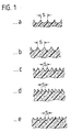
- FVW materials have an endless unidirectional placement of the reinforcing material layers on the structural surface, which are aligned in one direction and the matrix recedes so far from the fiber that grooves can be formed according to the examples shown in FIG. 1.
- a cross-sectional shape of a groove is shown, in which the sharp edges are turned outwards and the base is rounded.
- the sharp edges are also directed outwards, but the bottom is flat.
- This shape can now be achieved by various measures. Firstly, by appropriate design of the tool surface in the FVW laying technology or by surface treatment after the partial curing process of the FVW surface, for example by surface mechanical sandblasting. Furthermore, the shape can be shaped by surface contouring after Wrapping process take place during the drying phase or by forming the tear-off fabric on so-called FVW prepregs.
- the FVW materials have a directed or formed short fiber reinforcement layer on the structural surface in the form of so-called groove fields which are aligned with the desired or required surface groove shape.
- These resin fiber reinforcement layers can now be VERPREG scrims * or applied using the SMC technique.
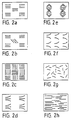
- a rectified groove field is sketched in example a in FIG. 2, it being true for this and all subsequent groove fields that the groove formation takes place in accordance with the examples or embodiments shown in FIG. 1.
- a rectified grooved field with a symmetrical transverse field is shown, and in example c, one with grooved fields offset by 90 ° to one another.
- Example d shows a non-parallel grooved field and example f shows a directed outlet grooved field.
- Example e is a closed triangular groove field, whereas it can also be a so-called tangled groove field - as shown in example g.
- a grooved field with parallel grooves of different lengths and positions is presented in example h.
- the groove formation is also as shown in FIG. 1, provided that it is parallel or approximately parallel and the distance between the grooves is S ⁇ S * (mm).
- the FVW materials can now also have an endless fiber structure, in which case these «fiber rovings» are processed in a weave (based on DIN 61 850).
- the best known are ATLAS, body and plain weave or their combinations.
- the MATRIX - regardless of its type - withdraws from the fiber surface.
Abstract
Description
Die Erfindung bezieht sich auf eine Einrichtung, zur Verringerung des strömungsmechanischen Reibungswiderstandes einer überströmten Struktur, insbesondere bei Luft- und Raumfahrzeugen sowie Wasserfahrzeugen, durch Aufbringen einer Rillenkonfiguration auf die Strukturoberfläche.The invention relates to a device for reducing the fluidic frictional resistance of an overflowed structure, in particular in the case of aircraft, spacecraft and watercraft, by applying a groove configuration to the structure surface.
Es ist bekannt, zusätzlich auf die umströmten Oberflächen von Tragstrukturen etc. Rillenkonfigurationen aufzubringen. Dies geschieht beispielsweise gemäß der WO 80/01673 durch die Bildung von zwei sich kreuzenden Strichsystemen, die zur Bewegungsrichtung Winkel bilden. Dadurch werden auf der Strukturoberfläche erhabene gitterförmige Strukturgebilde geschaffen, die nach einem anderen Vorschlag aus formgepreßten Folien gebildet und diese Folien an den Strukturoberflächen angeleimt werden.It is known to additionally apply groove configurations to the flow-around surfaces of support structures etc. According to WO 80/01673, this is done, for example, by the formation of two crossing stroke systems which form angles to the direction of movement. As a result, raised lattice-like structural structures are created on the structural surface, which according to another proposal are formed from compression-molded foils and these foils are glued to the structural surfaces.
In der DE-OS 1 923 633 wird zur Grenzschichtbeeinflussung von umströmten Körpern vorgeschlagen, einen Pelz nach Art einer Selbstklebefolie auf die Strukturoberfläche aufzukleben.In DE-OS 1 923 633, for influencing the boundary layer of flow-around bodies, it is proposed to glue a fur to the structure surface in the manner of a self-adhesive film.
In allen diesen Fällen ist jedoch ein zusätzlicher Arbeitsaufwand erforderlich, außerdem wird das Strukturgewicht erhöht. Wesentlicher ist jedoch, daß das Folienmaterial sehr erosions- und verletzungsgefährdet ist und aufgrund seiner geringen Lebensdauer erfordert, daß die Rillenoberflächen wiederholt aufgebracht werden müssen.In all these cases, however, additional work is required and the structural weight is increased. It is more important, however, that the film material is very susceptible to erosion and injury and, because of its short lifespan, requires that the groove surfaces have to be applied repeatedly.
Der vorliegenden Erfindung liegt die Aufgabe zugrunde, eine Einrichtung der eingangs genannten Art zu schaffen, die alle diese Nachteile beseitigt, d.h. ohne zusätzlichen Arbeits- und Gewichtsaufwand die Lebensdauer der Rillenoberflächenkonfiguration wesentlich erhöht.The present invention has for its object to provide a device of the type mentioned that eliminates all of these disadvantages, i.e. the service life of the groove surface configuration is significantly increased without additional work and weight.
Diese Aufgabe wird bei einer Einrichtung der vorgenannten Art dadurch gelöst, daß eine integrale Rillenoberfläche direkt aus dem Faserverbundwerkstoff-Material der herzustellenden Tragstruktur durch Formgebung bei Lege-, Oberflächenbehandlungs- oder Wickeltechnik während der Herstellung der überströmten Struktur gebildet wird. In den Unteransprüchen sind vorteilhafte Ausgestaltungen angegeben und in der nachfolgenden Beschreibung werden Ausführungsbeispiele behandelt, die in den Figuren der Zeichnung schematisch dargestellt sind. Es zeigen:
- Fig. 1 in den Beispielen a bis e Rillenformen verschiedener Querschnittsform;
- Fig. 2 in den Beispielen a bis h Rillenfelder verschiedener Ausgestaltung.
- 1 in examples a to e groove shapes of various cross-sectional shapes;
- Fig. 2 in the examples a to h grooved fields of various configurations.
Durch das Aufbringen einer Oberflächenmikrostruktur wird bekanntlich der Reibungswiderstand turbulenter Grenzschichten um gut 10% vermindert. Das beweist, daß solche «Rillenstrukturen» sowohl energietechnisch, wie auch energieökonomisch von Bedeutung sind. Solche Oberflächenmikrostrukturen sind deshalb bei allen überströmten Oberflächen von Vorteil, insbesondere bei Systemen mit Außenströmungsbelastungen, wie Flugzeuge, Wasser- und Landfahrzeuge. Der vorteilhafte Effekt tritt aber auch bei Systemen mit Innenströmungsbelastung genauso auf, also bei Einlaufströmungs- und Düsenströmungssystemen, Energietransportsystemen für Gas- oder Flüssigkeitsströmung und Förderkanäle.As is known, the application of a surface microstructure reduces the frictional resistance of turbulent boundary layers by a good 10%. This proves that such «groove structures» are important in terms of both energy technology and energy economics. Such surface microstructures are therefore advantageous for all surfaces overflowed, in particular for systems with external flow loads, such as aircraft, watercraft and land vehicles. However, the advantageous effect also occurs in systems with internal flow loading, that is to say in inlet flow and nozzle flow systems, energy transport systems for gas or liquid flow and delivery channels.
Da nun der Reibungswiderstand einer umströmten Oberfläche vor allem dort Bedeutung erlangt, wo höhere Transportgeschwindigkeiten auftreten, bedeutet dies gleichzeitig auch eine höhere mechanische Belastung dieser Oberfläche. Es ist zum einen denkbar, daß Oberflächen mit einer feinen Rillenstruktur S < S*, wobei S den Abstand zweier benachbarter Rillenoberkanten und S* den kritischen Abstand zweier benachbarter Rillenoberkanten darstellt, den Reibungswiderstand reduzieren, aber auch zum anderen bei geeigneter Rillenstruktur S < S* die Funktion von Turbulenzgeneratoren übernehmen können.Since the frictional resistance of a flowed-around surface now becomes particularly important where higher transport speeds occur, this also means a higher mechanical load on this surface. On the one hand, it is conceivable that surfaces with a fine groove structure S <S * , where S represents the distance between two adjacent upper groove edges and S * the critical distance between two adjacent upper groove edges, reduce the frictional resistance, but on the other hand with a suitable groove structure S <S * can take over the function of turbulence generators.
Für die Rillenstruktur gilt die Formel:
- γ die kinematische Zähigkeit an der Oberfläche
- p die Dichte
- 't", die Wandschubspannung an der glatten Oberfläche darstellen.
- γ the kinematic toughness on the surface
- p the density
- 't "representing the wall shear stress on the smooth surface.
Aufgrund der neuen Technologien werden Tragstrukturen wie Flügel, Rümpfe, Schalen, Behälter, Röhren usw. nicht mehr in Metallausführungen gefertigt, sondern aus Faserverbundwerkstoffen. Hier setzt nun die Erfindung ein und schlägt vor, schon bei der Herstellung der jeweils gewünschten Struktur integrale Rillenoberflächen vorzusehen und zwar so, daß die Rillen sich aus der Materialstruktur ergeben. Dies ist sowohl bei Duroplastmaterialien wie CFK, GFK, SFK bzw. Keramik- und Faserkeramikwerkstoffen möglich, wie auch bei Thermoplastwerkstoffen mit Fasereinlagen. Die Filamentdicke des jeweils gewählten Faserverbundwerkstoffes garantiert die notwendige Kantenschärfe solcher Rillen.Due to the new technologies, support structures such as wings, fuselages, shells, containers, tubes, etc. are no longer manufactured in metal versions, but from fiber composite materials. This is where the invention comes in and proposes to provide integral groove surfaces during the manufacture of the desired structure in such a way that the grooves result from the material structure. This is possible with thermoset materials such as CFRP, GFRP, SFK or ceramic and fiber ceramic materials, as well as with thermoplastic materials with fiber inserts. The filament thickness of the selected fiber composite material guarantees the necessary edge sharpness of such grooves.
Diese FVW-Materialien weisen eine endlos unidirektionale Verlegung der Verstärkungsmateriallagen auf der Strukturoberfläche auf, die nach einer Richtung ausgerichtet sind und wobei die Matrix so weit von der Faser zurücktritt, daß Rillen nach den in der Fig. 1 gezeigten Beispielen geformt werden können.These FVW materials have an endless unidirectional placement of the reinforcing material layers on the structural surface, which are aligned in one direction and the matrix recedes so far from the fiber that grooves can be formed according to the examples shown in FIG. 1.
Im Beispiel a ist eine Rillenquerschnittsform gezeigt, bei der die scharfen Kanten nach außen gestellt sind und der Boden rund gewölbt ist.In example a, a cross-sectional shape of a groove is shown, in which the sharp edges are turned outwards and the base is rounded.
m Beispiel b sind die scharfen Kanten ebenfalls nach außen gerichtet, der Boden ist jedoch eben.In example b, the sharp edges are also directed outwards, but the bottom is flat.
In den Beispielen c und d sind Sägezahnformen aufgezeigt und im Beispiel e ist ein Ausführungsbeispiel mit Doppeloberkante und Zwischeneinschnitt gezeigt. In allen Fällen herrscht die Bedingung S < S* < 0,25 mm vor.In examples c and d sawtooth shapes are shown and in example e an embodiment with a double top edge and intermediate cut is shown. In all cases, the condition S <S * <0.25 mm prevails.
Diese Formgebung läßt sich nun durch verschiedene Maßnahmen erreichen. Einmal durch entsprechende Gestaltung der Werkzeugoberfläche bei der FVW-Legetechnik oder durch Oberflächennachbehandlung nach dem Teilaushärteprozess der FVW-Oberfläche, beispielsweise durch oberflächenmechanisches Sandstrahlen. Weiterhin kann die Formgebung durch Oberflächenkonturierung nach dem Wickelprozess während der Trocknungsphase erfolgen oder durch Formieren des Abreißgewebes an sogenannten FVW-Prepregs.This shape can now be achieved by various measures. Firstly, by appropriate design of the tool surface in the FVW laying technology or by surface treatment after the partial curing process of the FVW surface, for example by surface mechanical sandblasting. Furthermore, the shape can be shaped by surface contouring after Wrapping process take place during the drying phase or by forming the tear-off fabric on so-called FVW prepregs.
In der Fig. 2 sind nun weitere Ausführungsbeispiele gezeigt, bei denen die FVW-Materialien eine gerichtete bzw. formierte Kurzfaserverstärkungslage auf der Strukturoberfläche in Form von sogenannten Rillenfeldern aufweisen, die nach gewünschter oder erforderlicher Oberflächenrillenform ausgerichtet sind. Diese Harzfaserverstärkungslagen können nun VERPREG-Gelege* seinodernachderSMC-Technik aufgebracht sein.2 now shows further exemplary embodiments in which the FVW materials have a directed or formed short fiber reinforcement layer on the structural surface in the form of so-called groove fields which are aligned with the desired or required surface groove shape. These resin fiber reinforcement layers can now be VERPREG scrims * or applied using the SMC technique.
In dem Beispiel a der Fig. 2 ist ein gleichgerichtetes Rillenfeld skizziert, wobei für dieses und alle nachfolgenden Rillenfelder gilt, daß die Rillenausbildung gemäß den in Fig. 1 aufgezeigten Beispielen bzw. Ausführungsformen erfolgt.A rectified groove field is sketched in example a in FIG. 2, it being true for this and all subsequent groove fields that the groove formation takes place in accordance with the examples or embodiments shown in FIG. 1.
In dem Ausführungsbeispiel b ist ein gleichgerichtetes Rillenfeld mit symmetrischem Querfeld gezeigt und im Beispiel c ein solches mit um 90° zueinander versetzten Rillenfeldern. Im Beispiel d wird ein nicht parallel gerichtetes Rillenfeld und im Beispiel f ein gerichtetes Auslaufrillenfeld gezeigt. Beim Beispiel e handelt es sich um ein geschlossenes Dreieck-Rillenfeld, wogegen es sich auch um ein sogenanntes Wirr-Rillenfeld - wie im Beispiel g gezeigt - handeln kann. Letztlich wird noch ein Rillenfeld mit parallelen Rillen verschiedener Länge und Lage im Beispiel h vorgestellt. Bei den Beispielen e bis h ist die Rillenausbildung ebenfalls so wie in Fig. 1 gezeigt, soweit diese parallel oder näherungsweise parallel und der Abstand der Rillen mit S < S* (mm) ausgeführt ist.In embodiment b, a rectified grooved field with a symmetrical transverse field is shown, and in example c, one with grooved fields offset by 90 ° to one another. Example d shows a non-parallel grooved field and example f shows a directed outlet grooved field. Example e is a closed triangular groove field, whereas it can also be a so-called tangled groove field - as shown in example g. Finally, a grooved field with parallel grooves of different lengths and positions is presented in example h. In examples e to h, the groove formation is also as shown in FIG. 1, provided that it is parallel or approximately parallel and the distance between the grooves is S <S * (mm).
Die FVW-Materialien können nun auch eine Endlos-Faserstruktur haben, wobei dann diese «Faserrovings» in Gewebebindung (in Anlehnung an DIN 61 850) verarbeitet sind. Die bekanntesten sind ATLAS-, Körper- und Leinwandbindung bzw. deren Kombinationen. Auch hier tritt die MATRIX - ganz gleich wie geartet - von der Faseroberfläche zurück.The FVW materials can now also have an endless fiber structure, in which case these «fiber rovings» are processed in a weave (based on DIN 61 850). The best known are ATLAS, body and plain weave or their combinations. Here too, the MATRIX - regardless of its type - withdraws from the fiber surface.
Claims (5)

Applications Claiming Priority (2)
| Application Number | Priority Date | Filing Date | Title |
|---|---|---|---|
| DE3534293 | 1985-09-26 | ||
| DE19853534293 DE3534293A1 (en) | 1985-09-26 | 1985-09-26 | DEVICE FOR REDUCING FRICTION RESISTANCE |
Publications (3)
| Publication Number | Publication Date |
|---|---|
| EP0216384A2 EP0216384A2 (en) | 1987-04-01 |
| EP0216384A3 EP0216384A3 (en) | 1987-11-25 |
| EP0216384B1 true EP0216384B1 (en) | 1989-12-20 |
Family
ID=6281978
Family Applications (1)
| Application Number | Title | Priority Date | Filing Date |
|---|---|---|---|
| EP86113218A Expired EP0216384B1 (en) | 1985-09-26 | 1986-09-25 | Device to reduce friction drag |
Country Status (3)
| Country | Link |
|---|---|
| US (1) | US4907765A (en) |
| EP (1) | EP0216384B1 (en) |
| DE (1) | DE3534293A1 (en) |
Families Citing this family (97)
| Publication number | Priority date | Publication date | Assignee | Title |
|---|---|---|---|---|
| US5133516A (en) * | 1985-05-31 | 1992-07-28 | Minnesota Mining And Manufacturing Co. | Drag reduction article |
| US4986496A (en) * | 1985-05-31 | 1991-01-22 | Minnesota Mining And Manufacturing | Drag reduction article |
| US5386955A (en) * | 1986-05-22 | 1995-02-07 | Rolls-Royce Plc | Control of fluid flow |
| EP0246916B1 (en) * | 1986-05-22 | 1992-06-24 | ROLLS-ROYCE plc | Boundary layer flow control |
| DE3772448D1 (en) * | 1986-05-22 | 1991-10-02 | Rolls Royce Plc | LIMIT LAYER FLOW CONTROL. |
| US4930729A (en) * | 1986-05-22 | 1990-06-05 | Rolls-Royce Plc | Control of fluid flow |
| GB8706554D0 (en) * | 1987-03-19 | 1987-04-23 | Rolls Royce Plc | Boundary layer devices |
| DE3762219D1 (en) * | 1986-05-22 | 1990-05-17 | Rolls Royce Plc | LIQUID FLOW CONTROL. |
| US5114099A (en) * | 1990-06-04 | 1992-05-19 | W. L. Chow | Surface for low drag in turbulent flow |
| AU5016493A (en) * | 1992-08-18 | 1994-03-15 | Four Winds Energy Corporation | Wind turbine particularly suited for high-wind conditions |
| DE4237307C2 (en) * | 1992-11-05 | 1994-08-18 | Voith Gmbh J M | Headbox of a machine forming a fibrous web |
| ES2064261B1 (en) * | 1993-02-25 | 1998-07-16 | Doria Iriarte Jose Javier | IMPROVED FUSELAGE IN ORDER TO ACHIEVE STABILIZATION EFFECTS OF TORBELLINOS. |
| DE4319628A1 (en) * | 1993-06-15 | 1994-12-22 | Klein Schanzlin & Becker Ag | Structured surfaces of fluid machine components |
| DE9316009U1 (en) * | 1993-10-20 | 1994-01-13 | Moser Josef | Surface of a fluid-flowed body |
| DE19613304A1 (en) * | 1996-04-03 | 1997-10-09 | Ernst Koelle | Upper surface structure for outer skin of bodies in flow medium |
| FR2751049B1 (en) | 1996-07-15 | 1998-09-18 | Inst Francais Du Petrole | MODIFIED SURFACE TO REDUCE THE TURBULENCE OF A FLUID AND METHOD OF TRANSPORTING |
| DE19631537C2 (en) * | 1996-07-23 | 1999-02-04 | Okoe Charles Dipl Ing Fh | Boundary layer profile for liquids and / or gases |
| DE19650439C1 (en) * | 1996-12-05 | 1998-03-12 | Deutsch Zentr Luft & Raumfahrt | Ribbed surface for wall subjected to turbulent airflow |
| US5833389A (en) * | 1996-12-09 | 1998-11-10 | Orlev Scientific Computing Ltd. | Apparatus for controlling turbulence in boundary layer and other wall-bounded fluid flow fields |
| US5884871A (en) * | 1997-03-27 | 1999-03-23 | Boeing North American, Inc. | Use of absorbing walls for laminar flow control |
| DE19725251C2 (en) * | 1997-06-14 | 2000-07-13 | Voith Hydro Gmbh & Co Kg | Method for producing a component for a hydraulic fluid machine, and a component produced thereafter |
| US5988568A (en) * | 1997-09-22 | 1999-11-23 | Drews; Hilbert F. P. | Surface modification apparatus and method for decreasing the drag or retarding forces created by fluids flowing across a moving surface |
| DE19840303A1 (en) * | 1998-09-04 | 2000-03-09 | Brandhorst Ingo | Micro turbulence generator system to reduce flow losses for motor vehicles consists of grained parts imprinted on self-adhesive foil for e.g. Formula 1 racing cars |
| US6303193B1 (en) * | 1998-11-05 | 2001-10-16 | General Electric Company | Process for fabricating a tool used in electrochemical machining |
| US6200439B1 (en) | 1998-11-05 | 2001-03-13 | General Electric Company | Tool for electrochemical machining |
| US6448669B1 (en) | 1998-12-01 | 2002-09-10 | Dillyn M. Elder | Water power generation system |
| US6191496B1 (en) | 1998-12-01 | 2001-02-20 | Dillyn M. Elder | Wind turbine system |
| NL1012753C2 (en) * | 1999-07-30 | 2001-02-01 | Chromalloy Holland B V | Gas turbine energy components with effectively reduced drag comprise a number of riblets on the gas flow surface of specific height, width and length |
| NL1014924C2 (en) * | 1999-07-30 | 2001-02-01 | Chromalloy Holland B V | Limitation of air resistance for components of a gas turbine engine. |
| US6387242B1 (en) | 1999-08-16 | 2002-05-14 | General Electric Company | Method and tool for electrochemical machining |
| US6234752B1 (en) | 1999-08-16 | 2001-05-22 | General Electric Company | Method and tool for electrochemical machining |
| US6290461B1 (en) | 1999-08-16 | 2001-09-18 | General Electric Company | Method and tool for electrochemical machining |
| DE10012666A1 (en) * | 2000-03-15 | 2001-09-20 | Fhp Motors Gmbh | Pump, in particular circulation pump for household machines such as washing machines and / or dishwashers |
| ES2195689B1 (en) * | 2000-07-26 | 2005-04-01 | Manuel Muñoz Saiz | SUSTAINING PROVISION FOR AIRPLANE SIDE SURFACES. |
| US6857604B2 (en) * | 2001-07-18 | 2005-02-22 | Eric T. Schmidt | Shock wave absorber |
| DE10139436A1 (en) | 2001-08-10 | 2003-03-06 | Airbus Gmbh | Device for reducing the fluidic frictional resistance |
| WO2003064254A2 (en) | 2002-01-30 | 2003-08-07 | Gulfstream Aerospace Corporation | Fuselage shaping and inclusion of spike on a supersonic aircraft for controlling and reducing sonic boom |
| US6698684B1 (en) | 2002-01-30 | 2004-03-02 | Gulfstream Aerospace Corporation | Supersonic aircraft with spike for controlling and reducing sonic boom |
| DE10217111A1 (en) * | 2002-04-17 | 2003-11-06 | Roehm Gmbh | Solid with microstructured surface |
| EP1371813A1 (en) * | 2002-06-13 | 2003-12-17 | ALSTOM (Switzerland) Ltd | Blading of a turbomachine |
| US7357351B2 (en) * | 2002-07-18 | 2008-04-15 | Eric T. Schmidt | Linear shock wave absorber |
| US6892989B1 (en) | 2003-05-29 | 2005-05-17 | The United States Of America As Represented By The Administrator Of The National Aeronautics And Space Administration | Method for reducing the drag of blunt-based vehicles by adaptively increasing forebody roughness |
| DE10357629A1 (en) † | 2003-12-10 | 2005-07-07 | Mtu Aero Engines Gmbh | Process for structuring the aerodynamics of components in aircraft gas turbines |
| DE102004009755A1 (en) * | 2004-02-28 | 2005-09-15 | Mtu Aero Engines Gmbh | Gas turbine blade |
| DE102004044655B4 (en) * | 2004-09-15 | 2009-06-10 | Airbus Deutschland Gmbh | Painting device, painting arrangement, method for painting a curved surface of an aircraft and use of an inkjet device for painting an aircraft |
| US20060068109A1 (en) * | 2004-09-15 | 2006-03-30 | Airbus Deutschland Gmbh | Painting device, painting arrangement, method for painting a curved surface of an object, and use of an inkjet device for painting an aircraft |
| US20060251859A1 (en) * | 2005-05-05 | 2006-11-09 | D Urso Brian R | Friction drag-reducing surface |
| US20070018055A1 (en) | 2005-07-11 | 2007-01-25 | Schmidt Eric T | Aerodynamically efficient surface |
| NL1029708C2 (en) * | 2005-08-10 | 2007-02-13 | Kick Off Ltd | Turbulence foil. |
| CA2998361C (en) | 2005-12-15 | 2020-04-28 | Gulfstream Aerospace Corporation | Isentropic compression inlet for supersonic aircraft |
| US8113469B2 (en) * | 2006-02-21 | 2012-02-14 | University Of Alabama | Passive micro-roughness array for drag modification |
| US20090065645A1 (en) * | 2007-02-05 | 2009-03-12 | United Technologies Corporation | Articles with reduced fluid dynamic drag |
| US8794574B2 (en) * | 2007-03-30 | 2014-08-05 | The Board Of Trustees Of The University Of Alabama | Micro-array surface for passive drag modification |
| NL1034178C2 (en) * | 2007-07-24 | 2009-01-27 | Kick Off Ltd | Friction resistance reducing layer for object e.g. vehicle, building, has repetitive waveform-like approach flow surface which has overhanging wave tops and cavities and grooves for transporting fluid from fluid boundary layer into cavities |
| NL1035216C2 (en) * | 2007-07-24 | 2009-01-27 | Kick Off Ltd | Friction-reducing reducing layer and method for the manufacture thereof. |
| FR2921448A1 (en) * | 2007-09-24 | 2009-03-27 | Snecma Sa | METHOD FOR FORMING RELIEF RELIEFS OF LIMITED LAYER |
| US8393158B2 (en) | 2007-10-24 | 2013-03-12 | Gulfstream Aerospace Corporation | Low shock strength inlet |
| US20090210103A1 (en) * | 2007-12-03 | 2009-08-20 | Mr. Michael Cook | Controlling aircraft aerial movements, defeating icing on aircraft surfaces, aiding decontamination, and damping turbulence effects on aircraft by the method of micro-perforated airfoil coordinated precision flow management |
| ES2585411T3 (en) * | 2008-08-05 | 2016-10-05 | Alcoa Inc. | Metal sheets and plates that have textured surfaces that reduce friction and methods to manufacture them |
| US8668166B2 (en) * | 2009-01-29 | 2014-03-11 | The Boeing Company | Shape memory riblets |
| US20100206038A1 (en) * | 2009-02-16 | 2010-08-19 | Santiago Vitagliano | Passive Turbulance Control Product for Minimizing Drag and Its Method of Manufacture |
| US8220754B2 (en) * | 2009-06-03 | 2012-07-17 | Lockheed Martin Corporation | Plasma enhanced riblet |
| FR2947313B1 (en) * | 2009-06-26 | 2015-02-20 | Inst Francais Du Petrole | SYSTEM AND METHOD FOR REDUCING TRAINING WITH STRUCTURED SURFACES OF EVOLUTIVE FORM |
| US20110186685A1 (en) * | 2010-02-02 | 2011-08-04 | The Boeing Company | Thin-Film Composite Having Drag-Reducing Riblets and Method of Making the Same |
| DE102010007570A1 (en) | 2010-02-10 | 2011-08-11 | ThyssenKrupp Nirosta GmbH, 47807 | Product for fluidic applications, process for its preparation and use of such a product |
| DE102011009998A1 (en) * | 2011-02-01 | 2012-08-02 | Airbus Operations Gmbh | Method for producing a flow body with a desired surface texturing and laser material removal device |
| DE102011106763A1 (en) * | 2011-07-05 | 2013-01-10 | Eads Deutschland Gmbh | A method of manufacturing a surface of a reduced airflow resistance component and a reduced airflow resistance component |
| DE102011121054A1 (en) * | 2011-12-14 | 2013-06-20 | Airbus Operations Gmbh | Riblet structure on a flow surface, method for producing a riblet structure on a flow surface and use of reinforcing elements in riblets for a flow area |
| GB2514214B (en) * | 2012-09-25 | 2015-04-22 | Messier Dowty Ltd | Aircraft component noise reducing patch |
| US10899045B2 (en) * | 2013-03-12 | 2021-01-26 | U.S.A. As Represented By The Administrator Of The National Aeronautics And Space Administration | High pressure soft lithography for micro-topographical patterning of molded polymers and composites |
| DE102013214075A1 (en) * | 2013-07-18 | 2015-01-22 | Fraunhofer-Gesellschaft zur Förderung der angewandten Forschung e.V. | Fabric with polymer layer |
| CN103407210B (en) * | 2013-08-02 | 2015-04-01 | 北京化工大学 | High-molecular biomimetic resistance-reducing surface and preparation device thereof |
| DE102013013817A1 (en) * | 2013-08-22 | 2015-02-26 | Airbus Defence and Space GmbH | Structural component with a riblet surface |
| DE202014104613U1 (en) | 2014-04-09 | 2015-08-11 | Kuka Systems Gmbh | applicator |
| US9308987B1 (en) | 2014-05-15 | 2016-04-12 | The Curators Of The University Of Missouri | Drag reduction utilizing driven micro-cavities |
| US20160243586A1 (en) * | 2014-08-01 | 2016-08-25 | The Boeing Company | Drag reduction riblets integrated in a paint layer |
| US10072511B2 (en) | 2014-10-02 | 2018-09-11 | Rolls-Royce North American Technologies Inc. | Engine nacelle |
| CN104613056A (en) * | 2015-01-21 | 2015-05-13 | 北京超微上达科技有限公司 | Bionic drag reduction surface for herringbone structure |
| US9482096B1 (en) * | 2015-04-28 | 2016-11-01 | The Boeing Company | Textured leading edge for aerospace and nautical structures |
| US10569365B2 (en) * | 2015-11-23 | 2020-02-25 | The Boeing Company | Method for preparing a fluid flow surface |
| US10322436B2 (en) | 2016-10-06 | 2019-06-18 | Nano And Advanced Materials Institute Limited | Method of coating interior surfaces with riblets |
| US11156099B2 (en) | 2017-03-28 | 2021-10-26 | General Electric Company | Turbine engine airfoil with a modified leading edge |
| CN107605874B (en) * | 2017-08-09 | 2019-11-15 | 浙江大学 | A kind of anti-cavitation corrosion micro-structure surface layer |
| FR3074546B1 (en) * | 2017-12-05 | 2020-07-10 | Wind-It | COATING SUITABLE FOR REDUCING THE TRAIL OF THE FLOW OF A FLUID AROUND A CYLINDRICAL ELEMENT |
| FR3076540B1 (en) * | 2018-01-08 | 2021-04-16 | Airbus Operations Sas | AERODYNAMIC ELEMENT OF AN AIRCRAFT, PROVIDED WITH A SET OF PROTUBERANT ELEMENTS. |
| US11492923B2 (en) * | 2018-04-09 | 2022-11-08 | Gulfstream Aerospace Corporation | Ice shedding aircraft engine |
| US10900509B2 (en) * | 2019-01-07 | 2021-01-26 | Rolls-Royce Corporation | Surface modifications for improved film cooling |
| EA037061B1 (en) * | 2019-01-25 | 2021-02-01 | Частное Учреждение "Назарбаев Университет Рисеч Энд Инновэйшн Систэм" | Centrifugal pump impeller blade |
| US11136673B2 (en) | 2019-02-08 | 2021-10-05 | The Boeing Company | Method of surface micro-texturing with a subtractive agent |
| US11142830B2 (en) | 2019-02-08 | 2021-10-12 | The Boeing Company | Method of surface micro-texturing with a subtractive agent |
| US20210231142A1 (en) * | 2019-08-21 | 2021-07-29 | Lockheed Martin Corporation | Submerged periodic riblets |
| US11614106B2 (en) | 2019-08-21 | 2023-03-28 | Lockheed Martin Corporation | Partially submerged periodic riblets |
| KR102403823B1 (en) * | 2019-12-13 | 2022-05-30 | 두산에너빌리티 주식회사 | Strut structure with strip for exhaust diffuser and gas turbine having the same |
| RU2757938C1 (en) * | 2020-09-18 | 2021-10-25 | Федеральное государственное унитарное предприятие "Центральный аэрогидродинамический институт имени профессора Н.Е. Жуковского" (ФГУП "ЦАГИ") | Aerodynamic wing airfoil for transonic speeds |
| US20220241645A1 (en) * | 2021-02-02 | 2022-08-04 | Iron Warrior Llc | Smart training system |
| WO2022225897A1 (en) | 2021-04-20 | 2022-10-27 | Nikon Corporation | Systems and methods for measuring height properties of surfaces |
| RU2763634C1 (en) * | 2021-04-28 | 2021-12-30 | федеральное государственное бюджетное образовательное учреждение высшего образования "Национальный исследовательский университет "МЭИ" (ФГБОУ ВО "НИУ "МЭИ") | Wide-angle flat, conical and axisymmetric ring diffusers |
Citations (1)
| Publication number | Priority date | Publication date | Assignee | Title |
|---|---|---|---|---|
| WO1980001673A1 (en) * | 1979-02-13 | 1980-08-21 | A Malmstroem | Surface structure of a surface adapted for movement relative to a fluid |
Family Cites Families (10)
| Publication number | Priority date | Publication date | Assignee | Title |
|---|---|---|---|---|
| NL218803A (en) * | 1956-07-09 | |||
| US3574040A (en) * | 1967-06-29 | 1971-04-06 | Gen Dynamics Corp | Apparatus for making laminated structural shapes by the controlled detrusive placement and polymerization of tectonic filamentous tapes |
| DE1923633A1 (en) * | 1969-05-09 | 1970-12-03 | Ursula Haenle | Boundary layer influencing of aerodynamic bodies |
| CA1099435A (en) * | 1971-04-01 | 1981-04-14 | Gwendyline Y. Y. T. Chen | Photosensitive block copolymer composition and elements |
| US3902944A (en) * | 1974-02-14 | 1975-09-02 | Fiber Science Inc | Noncircular filament wound article of manufacture and method of making same |
| US4060016A (en) * | 1976-07-26 | 1977-11-29 | Gerber Garment Technology, Inc. | Method and apparatus for blanking out pattern pieces from a layup |
| DE2942183A1 (en) * | 1979-10-18 | 1981-05-07 | Basf Ag, 6700 Ludwigshafen | PHOTOPOLYMERIZABLE MIXTURES AND ELEMENTS THEREOF |
| DE3137416A1 (en) * | 1981-09-19 | 1983-03-31 | Basf Ag, 6700 Ludwigshafen | PHOTOPOLYMERIZABLE MIXTURES AND ELEMENTS THEREOF |
| DE3528135A1 (en) * | 1985-08-06 | 1987-04-02 | Messerschmitt Boelkow Blohm | DEVICE FOR REDUCING FRICTION RESISTANCE |
| DE3621331A1 (en) * | 1986-06-26 | 1988-01-14 | Fraunhofer Ges Forschung | MICRO VALVE |
-
1985
- 1985-09-26 DE DE19853534293 patent/DE3534293A1/en active Granted
-
1986
- 1986-09-25 EP EP86113218A patent/EP0216384B1/en not_active Expired
-
1988
- 1988-04-07 US US07/183,330 patent/US4907765A/en not_active Expired - Lifetime
Patent Citations (1)
| Publication number | Priority date | Publication date | Assignee | Title |
|---|---|---|---|---|
| WO1980001673A1 (en) * | 1979-02-13 | 1980-08-21 | A Malmstroem | Surface structure of a surface adapted for movement relative to a fluid |
Also Published As
| Publication number | Publication date |
|---|---|
| US4907765A (en) | 1990-03-13 |
| EP0216384A2 (en) | 1987-04-01 |
| DE3534293A1 (en) | 1987-04-02 |
| EP0216384A3 (en) | 1987-11-25 |
| DE3534293C2 (en) | 1992-09-17 |
Similar Documents
| Publication | Publication Date | Title |
|---|---|---|
| EP0216384B1 (en) | Device to reduce friction drag | |
| DE102006035939B4 (en) | Process for the production of fiber composite components and fiber composite component | |
| DE3113791C2 (en) | ||
| EP3496936B1 (en) | Spar cap made of prefabricated elements with laid fabric and method for producing same | |
| DE102014015840B4 (en) | A method of manufacturing an I-stringer of an aircraft and apparatus for use in such methods | |
| WO1997012754A1 (en) | Process and device for producing large-surface structural elements by resin transfer moulding | |
| EP3444107A1 (en) | Method for manufacturing a sandwich component, core for a sandwich component and sandwich component | |
| EP0387400A2 (en) | Bulkhead | |
| DE3400043A1 (en) | METHOD FOR THE PRODUCTION OF ROD-SHAPED COMPONENTS OF LARGE EXTENSION, AND DEVICE FOR IMPLEMENTING THE METHOD | |
| DE2721651C3 (en) | Main wing connector for aircraft and spacecraft | |
| DE102011121054A1 (en) | Riblet structure on a flow surface, method for producing a riblet structure on a flow surface and use of reinforcing elements in riblets for a flow area | |
| EP2712724A1 (en) | Integral reinforcing elements | |
| DE102005030939A1 (en) | Method for producing a substantially cup-shaped component | |
| EP3286078B1 (en) | Control surface element | |
| EP3490782B1 (en) | Method for producing a three-dimensional, multi-layer fibre composite part | |
| DE2424068C3 (en) | Process for the production of a composite layer | |
| DE102018215356B4 (en) | Method for producing a fuselage component for an aircraft | |
| DE10037540B4 (en) | Technology for producing a fiber composite article | |
| DE102016123456A1 (en) | COMPRESSION TOOLS FOR MACHINING AIRCRAFT AND METHODS USING THROTTLE THREAD | |
| DE102007015516B4 (en) | Plastic-fiber composite component in the form of a profile with over the length varying profile cross-section | |
| DE102010023496B4 (en) | Fuselage segment of an aircraft | |
| EP0261375B1 (en) | Method for manufacturing a hollow fibre-reinforced composite beam | |
| DE102014221356A1 (en) | Assembly with individual components made of a fiber-reinforced composite material | |
| DE102018009379A1 (en) | New method for producing a flat component in some areas from a fiber composite material | |
| DE102020113677A1 (en) | A connection comprising a first component, a second component and a connection arrangement |
Legal Events
| Date | Code | Title | Description |
|---|---|---|---|
| PUAI | Public reference made under article 153(3) epc to a published international application that has entered the european phase |
Free format text: ORIGINAL CODE: 0009012 |
|
| AK | Designated contracting states |
Kind code of ref document: A2 Designated state(s): FR GB IT NL |
|
| PUAL | Search report despatched |
Free format text: ORIGINAL CODE: 0009013 |
|
| 17P | Request for examination filed |
Effective date: 19870813 |
|
| AK | Designated contracting states |
Kind code of ref document: A3 Designated state(s): FR GB IT NL |
|
| 17Q | First examination report despatched |
Effective date: 19890207 |
|
| GRAA | (expected) grant |
Free format text: ORIGINAL CODE: 0009210 |
|
| AK | Designated contracting states |
Kind code of ref document: B1 Designated state(s): FR GB IT NL |
|
| ET | Fr: translation filed | ||
| ITF | It: translation for a ep patent filed |
Owner name: STUDIO JAUMANN |
|
| GBT | Gb: translation of ep patent filed (gb section 77(6)(a)/1977) | ||
| PLBE | No opposition filed within time limit |
Free format text: ORIGINAL CODE: 0009261 |
|
| STAA | Information on the status of an ep patent application or granted ep patent |
Free format text: STATUS: NO OPPOSITION FILED WITHIN TIME LIMIT |
|
| 26N | No opposition filed | ||
| ITTA | It: last paid annual fee | ||
| PGFP | Annual fee paid to national office [announced via postgrant information from national office to epo] |
Ref country code: NL Payment date: 19960930 Year of fee payment: 11 |
|
| PG25 | Lapsed in a contracting state [announced via postgrant information from national office to epo] |
Ref country code: NL Free format text: LAPSE BECAUSE OF NON-PAYMENT OF DUE FEES Effective date: 19980401 |
|
| NLV4 | Nl: lapsed or anulled due to non-payment of the annual fee |
Effective date: 19980401 |
|
| PGFP | Annual fee paid to national office [announced via postgrant information from national office to epo] |
Ref country code: GB Payment date: 20010906 Year of fee payment: 16 |
|
| PGFP | Annual fee paid to national office [announced via postgrant information from national office to epo] |
Ref country code: FR Payment date: 20010920 Year of fee payment: 16 |
|
| REG | Reference to a national code |
Ref country code: GB Ref legal event code: IF02 |
|
| PG25 | Lapsed in a contracting state [announced via postgrant information from national office to epo] |
Ref country code: GB Free format text: LAPSE BECAUSE OF NON-PAYMENT OF DUE FEES Effective date: 20020925 |
|
| GBPC | Gb: european patent ceased through non-payment of renewal fee |
Effective date: 20020925 |
|
| PG25 | Lapsed in a contracting state [announced via postgrant information from national office to epo] |
Ref country code: FR Free format text: LAPSE BECAUSE OF NON-PAYMENT OF DUE FEES Effective date: 20030603 |
|
| REG | Reference to a national code |
Ref country code: FR Ref legal event code: ST |
|
| PG25 | Lapsed in a contracting state [announced via postgrant information from national office to epo] |
Ref country code: IT Free format text: LAPSE BECAUSE OF NON-PAYMENT OF DUE FEES;WARNING: LAPSES OF ITALIAN PATENTS WITH EFFECTIVE DATE BEFORE 2007 MAY HAVE OCCURRED AT ANY TIME BEFORE 2007. THE CORRECT EFFECTIVE DATE MAY BE DIFFERENT FROM THE ONE RECORDED. Effective date: 20050925 |