EP0127192A1 - Apparatus for producing perforated plastic film - Google Patents
Apparatus for producing perforated plastic film Download PDFInfo
- Publication number
- EP0127192A1 EP0127192A1 EP84106225A EP84106225A EP0127192A1 EP 0127192 A1 EP0127192 A1 EP 0127192A1 EP 84106225 A EP84106225 A EP 84106225A EP 84106225 A EP84106225 A EP 84106225A EP 0127192 A1 EP0127192 A1 EP 0127192A1
- Authority
- EP
- European Patent Office
- Prior art keywords
- film
- molding element
- element means
- screen
- perforated
- Prior art date
- Legal status (The legal status is an assumption and is not a legal conclusion. Google has not performed a legal analysis and makes no representation as to the accuracy of the status listed.)
- Granted
Links
Images


Classifications
-
- B—PERFORMING OPERATIONS; TRANSPORTING
- B26—HAND CUTTING TOOLS; CUTTING; SEVERING
- B26F—PERFORATING; PUNCHING; CUTTING-OUT; STAMPING-OUT; SEVERING BY MEANS OTHER THAN CUTTING
- B26F1/00—Perforating; Punching; Cutting-out; Stamping-out; Apparatus therefor
- B26F1/26—Perforating by non-mechanical means, e.g. by fluid jet
-
- B—PERFORMING OPERATIONS; TRANSPORTING
- B29—WORKING OF PLASTICS; WORKING OF SUBSTANCES IN A PLASTIC STATE IN GENERAL
- B29C—SHAPING OR JOINING OF PLASTICS; SHAPING OF MATERIAL IN A PLASTIC STATE, NOT OTHERWISE PROVIDED FOR; AFTER-TREATMENT OF THE SHAPED PRODUCTS, e.g. REPAIRING
- B29C59/00—Surface shaping of articles, e.g. embossing; Apparatus therefor
- B29C59/02—Surface shaping of articles, e.g. embossing; Apparatus therefor by mechanical means, e.g. pressing
- B29C59/06—Surface shaping of articles, e.g. embossing; Apparatus therefor by mechanical means, e.g. pressing using vacuum drums
Definitions
- the present invention relates to thermoplastic sheet and film products. More particularly, the invention relates to an apparatus for producing selectively apertured thermoplastic sheet or film.
- Perforated and embossed thermoplastic sheet or film have many useful applications.
- Perforated film is used in gardening and farming to prevent the growth of grass and other weeds while permitting more moisture to be transmitted through the film to the soil beneath.
- Perforated film is also used for making disposable baby diapers.
- U. S. Pat. No. 3,814,101 discloses diapers employing perforated thermoplastic film which permits the flow of liquid in the direction of the absorbent material in the diaper but substantially reduces the possibility of flow in the opposite direction.
- Embossed film without perforations are also used in making baby diapers, and in other applications where it is important that the film have a clothlike appearance or feel.
- thermoplastic sheet or film One of the methods for perforating thermoplastic sheet or film is disclosed in U. S. Pat. No. 3,054,148, issued to Zimmerli, which is hereby incorporated by reference.
- the Z immerli patent discloses a stationary drum having a molding element mounted around the outer surface of the drum and being adapted to rotate freely thereon.
- a vacuum chamber is employed beneath the screen or molding element to create a pressure differential between the respective surfaces of the thermoplastic sheet to cause the plasticized sheet to flow into the perforations provided in the molding element and thereby cause a series of holes to be formed in the sheet.
- An apparatus for the manufacture of selectively apertured thermoplastic film or sheet which comprises: a rotatable molding element means or screen for receiving the thermoplastic film and for imparting a desired pattern of perforated areas and non-apertured areas on the film upon contact therewith and the application of a fluid pressure differential to the surface of the film, each of said areas being continuous across the web of the film or sheet and alternating in the machine direction.
- a method is also provided for making a selectively apertured thermoplastic film in which apertured and non-apertured areas of the film are continuous across the web of the film and alternate in the machine direction.
- a stationary cylindrical roll or drum 10 is shown disposed about an axle 12.
- the outer cylindrical surface of the drum is preferably formed of highly polished metal but may be made of any other material having a relatively low coefficient of friction.
- a rotatable molding element or screen of the invention is generally indicated by the numeral 14 and is shown in Figs. 1 and 2 to be placed about the drum 10.
- Axle 12 defines the axis about which the molding element 14 rotates.
- the screen 14 is mounted around the surface of the drum 10 and is adapted to be rotated freely thereon.
- the screen may be formed as an integral unit in the shape of a cylinder and adapted to be slipped on the drum 10 from an end thereof or it may be wrapped around the drum 10 and then secured in any suitable manner.
- a gear drive may be employed which is adapted to mesh with gearing provided on the screen itself, or a pully drive may be connected to the molding element or screen by means of caps provided on the ends thereof.
- the screen could be rigidly attached to the drum 10 and the entire drum could be rotated, thereby rotating the screen 14. In effect, the screen 14 may be rotated about the drum in any desired manner by any suitable means.
- the screen 14 is composed of a cylindrical base pattern screen 20, an air flow restrictor sheet material 21, and an overlayed pattern screen 22.
- the base screen 20 is preferably made of metal or other suitable material of high heat conductivity to effect a reduction in the relative temperature of those portions of plasticized material which come in contact with the solid surface of the screen as distinguished from those portions of the plastic material which are directly over the perforations or voids in the screen.
- the screen can be made of a variety of materials and, depending on the effect desired, the perforations may be of many shapes and designs.
- the molding element may be made from a metal sheet or cylinder having the perforated design stamped or otherwise formed, normally by etching or plating techniques, or can be made of a woven wire mesh.
- the screen 20 provides the apertured or perforated area of the plastic sheet or film.
- the thin air flow restrictor sheet material 21, such as spunbonded-nonwoven remay polyester cloth is mounted over the outer surface of a portion of the cylindrical screen in a localized area from which a non-apertured or non-perforated film is desired.
- the restrictor material 21 is adhered to the screen with a spray adhesive or suitable equivalent.
- An overlay screen of any desired or predetermined pattern is cut to substantially the same size and shape as the overlayed restrictor material 21 and is soldered or otherwise secured in place around its entire perimeter. Testing has indicated that as much as two 5 mil layers of the remay material are required to completely eliminate formation of holes in the non-apertured areas.
- Other material, such as fine mesh, thin screens or the like are acceptable as restrictor material.
- the completed screen or molding element 14 when operated on standard vacuum equipment, with standard seals, produces a non-apertured film where the overlay has been applied and apertured film in all of the other areas. It can readily be appreciated that the application of the overlay provides an unlimited variety of configurations. The variety of selectively apertured film which can be produced on such a screen is basically unlimited.
- the vacuum chamber is schematically represented by the area 25 between the dotted lines at the end of the drum 10 and the surface of the drum 10.
- the vacuum chamber 25 may be any conventional vacuum chamber well known in the art.
- the vacuum chamber 25 is similar to that disclosed in the aforementioned Zimmerli patent although in the particular embodiment shown in the present invention, the drum 10 rotates about the axle 12 and the molding element or screen 14 rotates therewith.
- the area defined by the vacuum chamber 25 remains stationary within the drum.
- the base screen 20 has a plurality of holes 20a therein.
- the restrictor material 21 has a plurality of much smaller openings 21a therein.
- the overlay screen 22 has a plurality of openings 22a therein which are designed to impart a particular shaped perforation or aperture in the plastic film.
- the multilayer screen 14 is also illustrated in Fig. 9 and each of the screens 20, 21 and 22 with their respective openings 20a, 21a and 22a can be readily seen.
- a plastic sheet or film 30 is shown which has non-apertured areas 31 and 32 on each side thereof and an apertured portion 33 in the center thereof between the non-apertured areas.
- the machine direction of the film 30 is indicated at A.
- a portion of the film 30 is illustrated showing non-apertured depressions 31a and apertured depressions 33a with openings or perforations 33b therein. It can be appreciated that this is only one illustration of a type of embossment or depression that can be imparted to a plastic film.
- a plastic film 40 which can be prepared on a screen of the present invention wherein the machine direction is as indicated in B.
- the plastic film 40 has non-perforated areas 41 and 42 and a perforated area 43.
- the embossings or depressions are similar to those illustrated in Fig. 5, but can be of a variety of constructions as desired.
- a portion of a plastic film 50 is illustrated which has a series of generally hexagonally-shaped depressions 51 attached at their edges.
- the hexagonal depressions have elliptical-shaped holes 52 centered therein.
- Another portion of the film 50 has similarly shaped hexagonal depressions 53, but these do not have the holes 52 therein.
- This film is only one type which can be manufactured on the screen of the present invention.
- Fig. 8 which is illustrative of a screen 114 which has a base screen 120 having a plurality of openings 120a therein and on which is positioned a remay polyester cloth 121 and an overlay screen 122 having openings 122a therein positioned over the cloth 121.
- the screen 114 may be seen with its separate layers 120, 121 and 122. Openings or holes 120a and 122a may be seen in their respective screens 120 and 122.
- the screen of the present invention may be used with any thermoplastic material which can be formed into flexible film or sheets.
- exemplary thermoplastic materials include cellulose, e.g., cellulose acetate, cellulose propionate, cellulose butyrate; mixed esters of cellulose; cellulose ethers, e.g., ethyl cellulose; nylon or polymeric materials, e.g. polyvinyl alcohol acetals, polyvinyl chloride, polyvinyl chloride acetate, polystyrene, methyl methacrylate, polyethylene, polypropylene, and other polyolefins which may be formed into flexible sheet or film, and the like. Polyolefins are preferred and polyethylene is especially preferred. Sheets or films made from cellulose materials may be plasticized with suitable plasticizers and other additives known in the art may be added to achieve a desired physical characteristic.
- screens cloth, or other material combinations which when overlayed and bonded to a base cylindrical screen will produce selectively apertured film, via a vacuum process and which film has an unlimited variety of sizes, shapes and texture qualities.
- films can be produced which have repetitive areas differing in pattern, porosity, texture, appearance and mechanical properties.
- thermoly resistant materials In addition to remay polyester cloth, other breathable thermally resistant materials can be used.
Abstract
Description
- The present invention relates to thermoplastic sheet and film products. More particularly, the invention relates to an apparatus for producing selectively apertured thermoplastic sheet or film.
- Perforated and embossed thermoplastic sheet or film have many useful applications. Perforated film is used in gardening and farming to prevent the growth of grass and other weeds while permitting more moisture to be transmitted through the film to the soil beneath. Perforated film is also used for making disposable baby diapers. U. S. Pat. No. 3,814,101 discloses diapers employing perforated thermoplastic film which permits the flow of liquid in the direction of the absorbent material in the diaper but substantially reduces the possibility of flow in the opposite direction. Embossed film without perforations are also used in making baby diapers, and in other applications where it is important that the film have a clothlike appearance or feel.
- One of the methods for perforating thermoplastic sheet or film is disclosed in U. S. Pat. No. 3,054,148, issued to Zimmerli, which is hereby incorporated by reference. The Zimmerli patent discloses a stationary drum having a molding element mounted around the outer surface of the drum and being adapted to rotate freely thereon. A vacuum chamber is employed beneath the screen or molding element to create a pressure differential between the respective surfaces of the thermoplastic sheet to cause the plasticized sheet to flow into the perforations provided in the molding element and thereby cause a series of holes to be formed in the sheet.
- More recently, various apparatuses have been constructed to produce a variety of types of perforated plastic film. These are illustrated by U. S. 4,155,693 and U. S. 4,157,237, issued to Raley, and U. S. 4,252,516 issued to Raley and Adams. Although all of these devices are effective for their intended purposes, they have limited capability for producing selectively apertured or perforated film.
- In general, to successfully aperture or perforate a film on vacuum process equipment, a minimum vacuum level and a minimum melt temperature must be maintained. In order to prevent operating in a selected area one or both of these conditions must be lowered in that area but only to the extent that holes or perforations are not formed and the pattern retained.
- Previously, it has been possible to manufacture an apertured/non-apertured thermoplastic film only with the apertured area and non-apertured area alternating across the web of the film and running continuously in the machine direction. Production of a film of this type requires modification of the stationary seals within the vacuum roll or drum. The modification is accomplished by cutting back the seals to provide a controlled vacuum leak. The latter produces the non-perforated area during production of the film.
- Since the screen or molding element rotates with the web it is desirable to produce a screen which will produce a selectively apertured film of any desired configuration.
- Elimination of the seal cut back requirement facilitates changing from one type of product to another.
- An apparatus is provided for the manufacture of selectively apertured thermoplastic film or sheet which comprises: a rotatable molding element means or screen for receiving the thermoplastic film and for imparting a desired pattern of perforated areas and non-apertured areas on the film upon contact therewith and the application of a fluid pressure differential to the surface of the film, each of said areas being continuous across the web of the film or sheet and alternating in the machine direction.
- A method is also provided for making a selectively apertured thermoplastic film in which apertured and non-apertured areas of the film are continuous across the web of the film and alternate in the machine direction.
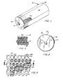
- Fig. 1 is a perspective view of a perforating drum with a screen positioned thereon;
- Fig. 2 is an end view of the drum of Fig. 1;
- Fig. 3 is a cut-away, enlarged view of a portion of the screen of Figs. 1 and 2;
- Fig. 4 is a top plan view of a section of plastic film having apertured and non-apertured areas alternating across the web of the film and running continuously in the machine direction;
- Fig. 5 is an enlarged sectional view of the plastic film taken along line 5-5 of Fig. 4;
- Fig. 6 is a view similar to that of Fig. 4 with the plastic film having apertured and non-apertured areas alternating in the machine direction.
- Fig. 7 is an enlarged view of a small portion of the plastic film of Fig. 4;
- Fig. 8 is a cut-away enlarged view of a portion of an alternate screen construction;
- Fig. 9 is a sectional view taken along line 9-9 of Fig. 3; and,
- Fig. 10 is a sectional view taken along line 10-10 of Fig. 8.
- Referring now to Figs. 1 and 2 of the drawings, a stationary cylindrical roll or
drum 10 is shown disposed about anaxle 12. The outer cylindrical surface of the drum is preferably formed of highly polished metal but may be made of any other material having a relatively low coefficient of friction. A rotatable molding element or screen of the invention is generally indicated by thenumeral 14 and is shown in Figs. 1 and 2 to be placed about thedrum 10.Axle 12 defines the axis about which themolding element 14 rotates. - The
screen 14 is mounted around the surface of thedrum 10 and is adapted to be rotated freely thereon. The screen may be formed as an integral unit in the shape of a cylinder and adapted to be slipped on thedrum 10 from an end thereof or it may be wrapped around thedrum 10 and then secured in any suitable manner. For the purpose of rotating thescreen 14, a gear drive may be employed which is adapted to mesh with gearing provided on the screen itself, or a pully drive may be connected to the molding element or screen by means of caps provided on the ends thereof. If desired, the screen could be rigidly attached to thedrum 10 and the entire drum could be rotated, thereby rotating thescreen 14. In effect, thescreen 14 may be rotated about the drum in any desired manner by any suitable means. - The
screen 14 is composed of a cylindricalbase pattern screen 20, an air flowrestrictor sheet material 21, and an overlayedpattern screen 22. - The
base screen 20 is preferably made of metal or other suitable material of high heat conductivity to effect a reduction in the relative temperature of those portions of plasticized material which come in contact with the solid surface of the screen as distinguished from those portions of the plastic material which are directly over the perforations or voids in the screen. The screen can be made of a variety of materials and, depending on the effect desired, the perforations may be of many shapes and designs. The molding element may be made from a metal sheet or cylinder having the perforated design stamped or otherwise formed, normally by etching or plating techniques, or can be made of a woven wire mesh. Thescreen 20 provides the apertured or perforated area of the plastic sheet or film. - The thin air flow
restrictor sheet material 21, such as spunbonded-nonwoven remay polyester cloth is mounted over the outer surface of a portion of the cylindrical screen in a localized area from which a non-apertured or non-perforated film is desired. Therestrictor material 21 is adhered to the screen with a spray adhesive or suitable equivalent. An overlay screen of any desired or predetermined pattern is cut to substantially the same size and shape as the overlayedrestrictor material 21 and is soldered or otherwise secured in place around its entire perimeter. Testing has indicated that as much as two 5 mil layers of the remay material are required to completely eliminate formation of holes in the non-apertured areas. Other material, such as fine mesh, thin screens or the like are acceptable as restrictor material. The completed screen ormolding element 14 when operated on standard vacuum equipment, with standard seals, produces a non-apertured film where the overlay has been applied and apertured film in all of the other areas. It can readily be appreciated that the application of the overlay provides an unlimited variety of configurations. The variety of selectively apertured film which can be produced on such a screen is basically unlimited. - Also in Figs. 1 and 2, the vacuum chamber is schematically represented by the
area 25 between the dotted lines at the end of thedrum 10 and the surface of thedrum 10. Thevacuum chamber 25 may be any conventional vacuum chamber well known in the art. Thevacuum chamber 25 is similar to that disclosed in the aforementioned Zimmerli patent although in the particular embodiment shown in the present invention, thedrum 10 rotates about theaxle 12 and the molding element orscreen 14 rotates therewith. The area defined by thevacuum chamber 25 remains stationary within the drum. - Referring now to Fig. 3, an enlarged portion of a *
screen 14 is illustrated. Thebase screen 20 has a plurality of holes 20a therein. Therestrictor material 21 has a plurality of much smaller openings 21a therein. Theoverlay screen 22 has a plurality of openings 22a therein which are designed to impart a particular shaped perforation or aperture in the plastic film. Themultilayer screen 14 is also illustrated in Fig. 9 and each of thescreens - It can be appreciated that other arrangements of restrictor material or
screen 21 andoverlay screen 22 may be made around thebase screen 20 to produce a particular patterned or selectively apertured plastic sheet or film. Referring to Fig. 4, a plastic sheet orfilm 30 is shown which hasnon-apertured areas apertured portion 33 in the center thereof between the non-apertured areas. The machine direction of thefilm 30 is indicated at A. - In Fig. 5, a portion of the
film 30 is illustrated showing non-apertured depressions 31a and apertured depressions 33a with openings or perforations 33b therein. It can be appreciated that this is only one illustration of a type of embossment or depression that can be imparted to a plastic film. - In Fig. 6, a
plastic film 40 is shown which can be prepared on a screen of the present invention wherein the machine direction is as indicated in B. Theplastic film 40 hasnon-perforated areas perforated area 43. The embossings or depressions are similar to those illustrated in Fig. 5, but can be of a variety of constructions as desired. - Referring now to Fig. 7 a portion of a plastic film 50 is illustrated which has a series of generally hexagonally-shaped depressions 51 attached at their edges. The hexagonal depressions have elliptical-shaped holes 52 centered therein. Another portion of the film 50 has similarly shaped hexagonal depressions 53, but these do not have the holes 52 therein. This film is only one type which can be manufactured on the screen of the present invention.
- Fig. 8, which is illustrative of a
screen 114 which has abase screen 120 having a plurality of openings 120a therein and on which is positioned aremay polyester cloth 121 and anoverlay screen 122 having openings 122a therein positioned over thecloth 121. In Fig. 10, thescreen 114 may be seen with itsseparate layers respective screens - The screen of the present invention may be used with any thermoplastic material which can be formed into flexible film or sheets. Exemplary thermoplastic materials include cellulose, e.g., cellulose acetate, cellulose propionate, cellulose butyrate; mixed esters of cellulose; cellulose ethers, e.g., ethyl cellulose; nylon or polymeric materials, e.g. polyvinyl alcohol acetals, polyvinyl chloride, polyvinyl chloride acetate, polystyrene, methyl methacrylate, polyethylene, polypropylene, and other polyolefins which may be formed into flexible sheet or film, and the like. Polyolefins are preferred and polyethylene is especially preferred. Sheets or films made from cellulose materials may be plasticized with suitable plasticizers and other additives known in the art may be added to achieve a desired physical characteristic.
- It can be appreciated that a wide variety of screens, cloth, or other material combinations which when overlayed and bonded to a base cylindrical screen will produce selectively apertured film, via a vacuum process and which film has an unlimited variety of sizes, shapes and texture qualities. Using screens of this invention films can be produced which have repetitive areas differing in pattern, porosity, texture, appearance and mechanical properties.
- In addition to remay polyester cloth, other breathable thermally resistant materials can be used.
Claims (10)
Applications Claiming Priority (2)
| Application Number | Priority Date | Filing Date | Title |
|---|---|---|---|
| US06/499,857 US4541794A (en) | 1983-06-01 | 1983-06-01 | Apparatus for producing perforated plastic film |
| US499857 | 1990-03-27 |
Publications (2)
| Publication Number | Publication Date |
|---|---|
| EP0127192A1 true EP0127192A1 (en) | 1984-12-05 |
| EP0127192B1 EP0127192B1 (en) | 1987-07-22 |
Family
ID=23987026
Family Applications (1)
| Application Number | Title | Priority Date | Filing Date |
|---|---|---|---|
| EP84106225A Expired EP0127192B1 (en) | 1983-06-01 | 1984-05-30 | Apparatus for producing perforated plastic film |
Country Status (5)
| Country | Link |
|---|---|
| US (1) | US4541794A (en) |
| EP (1) | EP0127192B1 (en) |
| JP (1) | JPS6068928A (en) |
| CA (1) | CA1243175A (en) |
| DE (1) | DE3464863D1 (en) |
Cited By (8)
| Publication number | Priority date | Publication date | Assignee | Title |
|---|---|---|---|---|
| EP0205289A1 (en) * | 1985-05-31 | 1986-12-17 | Minnesota Mining And Manufacturing Company | Drag reduction article |
| US5133516A (en) * | 1985-05-31 | 1992-07-28 | Minnesota Mining And Manufacturing Co. | Drag reduction article |
| EP0705933A2 (en) * | 1994-09-16 | 1996-04-10 | McNEIL-PPC, INC. | Apparatus for making nonwoven fabrics having raised portions |
| GB2295166A (en) * | 1994-11-21 | 1996-05-22 | Tohoku Ricoh Co Limited | Porous sheet for the drum of a stencil printer |
| WO1997022434A1 (en) * | 1995-12-18 | 1997-06-26 | Mcneil-Ppc, Inc. | Laser drilling processes for making fabric and film forming devices |
| US5740734A (en) * | 1995-02-10 | 1998-04-21 | Tohoku Ricoh Co., Ltd. | Drum and stencil for a stencil printer |
| US5906159A (en) * | 1996-03-26 | 1999-05-25 | Tohoku Ricoh Co., Ltd. | Stencil ink holding member made of sintered fibers |
| EP2261117A3 (en) * | 2009-06-12 | 2017-05-03 | Peter Adrian Leitl | Method for producing a microstructured film |
Families Citing this family (15)
| Publication number | Priority date | Publication date | Assignee | Title |
|---|---|---|---|---|
| US4636161A (en) * | 1983-06-01 | 1987-01-13 | Ethyl Corporation | Screen for selectively perforating thermoplastic film |
| US4741877A (en) * | 1983-10-17 | 1988-05-03 | The Procter & Gamble Company | Uniformly debossing and aperturing a moving plastic web using stationary support member in forming area |
| DE3476015D1 (en) * | 1983-10-17 | 1989-02-16 | Procter & Gamble | Method and apparatus for uniformly debossing and optionally aperturing a moving plastic web |
| FI70388C (en) * | 1985-07-24 | 1986-09-19 | Uponor Ab | SAETT OCH ANORDNING FOER ATT AOSTADKOMMA ETT HAOL I ETT PLASTROER |
| ES2092305T3 (en) | 1992-04-27 | 1996-11-16 | Dowbrands Inc | MICROPERFORATED FILM AND PACKAGING BAG MADE FROM THE SAME. |
| WO1996026697A1 (en) | 1995-02-28 | 1996-09-06 | Tredegar Industries, Inc. | Three-dimensional film formed by melt bonding fibers on the surface of a polymeric film |
| US5628856A (en) * | 1996-04-29 | 1997-05-13 | The Procter & Gamble Company | Method for forming a composite elastic material |
| US5645672A (en) * | 1996-06-24 | 1997-07-08 | The Proctor & Gamble Company | Method for forming a composite elastic material |
| US6024553A (en) | 1997-12-22 | 2000-02-15 | Mcneil-Ppc, Inc. | Apparatus for supporting a starting web during formation of the apertured web |
| US6700036B2 (en) | 2000-09-22 | 2004-03-02 | Tredegar Film Products Corporation | Acquisition distribution layer having void volumes for an absorbent article |
| US6610904B1 (en) | 2000-09-22 | 2003-08-26 | Tredegar Film Products Corporation | Acquisition distribution layer having void volumes for an absorbent article |
| US20030195487A1 (en) * | 2000-09-22 | 2003-10-16 | Tredegar Film Products Corporation | Absorbent article with enhanced cooling |
| TW564818U (en) * | 2002-09-04 | 2003-12-01 | Jen-Jeng Huang | Multi-surface diffusion holed structure and manufacturing device therefor |
| US7021918B1 (en) | 2005-02-07 | 2006-04-04 | Reum Sr Donald J | Apparatus for shaping and perforating a plastic film |
| US8292863B2 (en) | 2009-10-21 | 2012-10-23 | Donoho Christopher D | Disposable diaper with pouches |
Citations (8)
| Publication number | Priority date | Publication date | Assignee | Title |
|---|---|---|---|---|
| US2776451A (en) * | 1952-02-16 | 1957-01-08 | Chavannes Ind Synthetics Inc | Apparatus for method for producing embossed thermoplastic film |
| AT219268B (en) * | 1957-01-05 | 1962-01-25 | United Plastics Ind Inc | Device for embossing thermoplastic films or the like. |
| US3054148A (en) * | 1951-12-06 | 1962-09-18 | Zimmerli William Frederick | Process of producing a perforated thermoplastic sheet |
| GB909352A (en) * | 1958-01-07 | 1962-10-31 | Robert John Trewella | Embossing, Perforating and Cutting Thermoplastic Sheet Material. |
| DE2746440A1 (en) * | 1976-10-19 | 1978-04-20 | Procter & Gamble | PROCESS FOR EMBOSSING AND PERFORATING A RUNNING TAPE OF THERMOPLASTIC FILM AND DEVICE FOR CARRYING OUT THE PROCESS |
| US4155693A (en) * | 1978-07-24 | 1979-05-22 | Ethyl Corporation | Embossed screen assembly |
| US4157237A (en) * | 1978-07-10 | 1979-06-05 | Ethyl Corporation | Molding element for producing thermoplastic film |
| US4252516A (en) * | 1979-08-23 | 1981-02-24 | Ethyl Corporation | Apparatus for producing perforated film |
Family Cites Families (3)
| Publication number | Priority date | Publication date | Assignee | Title |
|---|---|---|---|---|
| US3679535A (en) * | 1970-03-24 | 1972-07-25 | Johnson & Johnson | Nonwoven fabric comprising discontinuous groups of small holes connected by ribbons defining large holes |
| US4395215A (en) * | 1981-02-02 | 1983-07-26 | The Procter & Gamble Company | Film forming structure for uniformly debossing and selectively aperturing a resilient plastic web and method for its construction |
| EP0059506B2 (en) * | 1981-03-02 | 1994-01-26 | THE PROCTER & GAMBLE COMPANY | Macroscopically expanded three-dimensional plastic web exhibiting non-glossy visible surface and cloth-like tactile impression and process for its manufacture |
-
1983
- 1983-06-01 US US06/499,857 patent/US4541794A/en not_active Expired - Lifetime
-
1984
- 1984-05-25 CA CA000455153A patent/CA1243175A/en not_active Expired
- 1984-05-30 DE DE8484106225T patent/DE3464863D1/en not_active Expired
- 1984-05-30 EP EP84106225A patent/EP0127192B1/en not_active Expired
- 1984-06-01 JP JP59112911A patent/JPS6068928A/en active Granted
Patent Citations (8)
| Publication number | Priority date | Publication date | Assignee | Title |
|---|---|---|---|---|
| US3054148A (en) * | 1951-12-06 | 1962-09-18 | Zimmerli William Frederick | Process of producing a perforated thermoplastic sheet |
| US2776451A (en) * | 1952-02-16 | 1957-01-08 | Chavannes Ind Synthetics Inc | Apparatus for method for producing embossed thermoplastic film |
| AT219268B (en) * | 1957-01-05 | 1962-01-25 | United Plastics Ind Inc | Device for embossing thermoplastic films or the like. |
| GB909352A (en) * | 1958-01-07 | 1962-10-31 | Robert John Trewella | Embossing, Perforating and Cutting Thermoplastic Sheet Material. |
| DE2746440A1 (en) * | 1976-10-19 | 1978-04-20 | Procter & Gamble | PROCESS FOR EMBOSSING AND PERFORATING A RUNNING TAPE OF THERMOPLASTIC FILM AND DEVICE FOR CARRYING OUT THE PROCESS |
| US4157237A (en) * | 1978-07-10 | 1979-06-05 | Ethyl Corporation | Molding element for producing thermoplastic film |
| US4155693A (en) * | 1978-07-24 | 1979-05-22 | Ethyl Corporation | Embossed screen assembly |
| US4252516A (en) * | 1979-08-23 | 1981-02-24 | Ethyl Corporation | Apparatus for producing perforated film |
Cited By (17)
| Publication number | Priority date | Publication date | Assignee | Title |
|---|---|---|---|---|
| EP0205289A1 (en) * | 1985-05-31 | 1986-12-17 | Minnesota Mining And Manufacturing Company | Drag reduction article |
| US4986496A (en) * | 1985-05-31 | 1991-01-22 | Minnesota Mining And Manufacturing | Drag reduction article |
| US5069403A (en) * | 1985-05-31 | 1991-12-03 | Minnesota Mining And Manufacturing Company | Drag reduction article |
| US5133516A (en) * | 1985-05-31 | 1992-07-28 | Minnesota Mining And Manufacturing Co. | Drag reduction article |
| EP0705933A3 (en) * | 1994-09-16 | 1997-10-01 | Mcneil Ppc Inc | Apparatus for making nonwoven fabrics having raised portions |
| EP0705933A2 (en) * | 1994-09-16 | 1996-04-10 | McNEIL-PPC, INC. | Apparatus for making nonwoven fabrics having raised portions |
| CN1064728C (en) * | 1994-09-16 | 2001-04-18 | 麦克尼尔-Ppc公司 | Apparatus for making nonwoven fabrics having raised portions |
| USRE38105E1 (en) | 1994-09-16 | 2003-05-06 | Mcneil-Ppc, Inc. | Apparatus for making nonwoven fabrics having raised portions |
| GB2295166A (en) * | 1994-11-21 | 1996-05-22 | Tohoku Ricoh Co Limited | Porous sheet for the drum of a stencil printer |
| US5662040A (en) * | 1994-11-21 | 1997-09-02 | Tohoku Ricoh Co., Ltd. | Structures of a drum and a stencil for a stencil printer |
| GB2295166B (en) * | 1994-11-21 | 1998-09-02 | Tohoku Riko Kk | Structures of a drum and a stencil for a stencil printer |
| US5740734A (en) * | 1995-02-10 | 1998-04-21 | Tohoku Ricoh Co., Ltd. | Drum and stencil for a stencil printer |
| US5855169A (en) * | 1995-02-10 | 1999-01-05 | Tohoku Ricoh Co., Ltd. | Drum and stencil for a stencil printing |
| WO1997022434A1 (en) * | 1995-12-18 | 1997-06-26 | Mcneil-Ppc, Inc. | Laser drilling processes for making fabric and film forming devices |
| AU711811B2 (en) * | 1995-12-18 | 1999-10-21 | Mcneil-Ppc, Inc. | Laser drilling processes for making fabric and film forming devices |
| US5906159A (en) * | 1996-03-26 | 1999-05-25 | Tohoku Ricoh Co., Ltd. | Stencil ink holding member made of sintered fibers |
| EP2261117A3 (en) * | 2009-06-12 | 2017-05-03 | Peter Adrian Leitl | Method for producing a microstructured film |
Also Published As
| Publication number | Publication date |
|---|---|
| EP0127192B1 (en) | 1987-07-22 |
| DE3464863D1 (en) | 1987-08-27 |
| US4541794A (en) | 1985-09-17 |
| CA1243175A (en) | 1988-10-18 |
| JPH0126858B2 (en) | 1989-05-25 |
| JPS6068928A (en) | 1985-04-19 |
Similar Documents
| Publication | Publication Date | Title |
|---|---|---|
| EP0127192A1 (en) | Apparatus for producing perforated plastic film | |
| US4636161A (en) | Screen for selectively perforating thermoplastic film | |
| US4644623A (en) | Method of making a rotatable molding element for selectively aperturing thermoplastic film | |
| US4252516A (en) | Apparatus for producing perforated film | |
| US4317792A (en) | Process for producing perforated film | |
| US4351784A (en) | Corona treatment of perforated film | |
| CA1125980A (en) | Embossed screen assembly | |
| US5591510A (en) | Layered fabric material having angled capillaries | |
| CA2225719C (en) | Screen for producing a perforated film | |
| US6024553A (en) | Apparatus for supporting a starting web during formation of the apertured web | |
| EP0859700B1 (en) | Film with angled capillaries | |
| US5897543A (en) | Film | |
| US4622036A (en) | Porous film and absorptive structure | |
| US5824352A (en) | Apparatus for producing an apertured plastic film having a tricot texture | |
| JP3150010B2 (en) | Method of forming a web, apparatus for producing a perforated web and web or film product having a plurality of holes on a surface | |
| US4839216A (en) | Formed material produced by solid-state formation with a high-pressure liquid stream | |
| IE53139B1 (en) | Apparatus and method for debossing and selectively aperturing a resilient plastic web | |
| RU95115980A (en) | PERFORATED PLASTIC FILM | |
| US4157237A (en) | Molding element for producing thermoplastic film | |
| CA1125973A (en) | Method and apparatus for producing perforated film | |
| GB2103933A (en) | Absorbent pad with perforated cover | |
| KR100339933B1 (en) | MicroPerforation and Microembossing Method of Polymeric Webs | |
| MXPA98000617A (en) | Movie with capillaries in ang | |
| US3762255A (en) | Method and apparatus for piercing thin sheet material | |
| JPS6356541A (en) | Liquid permeable sheet material |
Legal Events
| Date | Code | Title | Description |
|---|---|---|---|
| PUAI | Public reference made under article 153(3) epc to a published international application that has entered the european phase |
Free format text: ORIGINAL CODE: 0009012 |
|
| AK | Designated contracting states |
Designated state(s): BE DE FR GB IT LU NL |
|
| 17P | Request for examination filed |
Effective date: 19841029 |
|
| GRAA | (expected) grant |
Free format text: ORIGINAL CODE: 0009210 |
|
| AK | Designated contracting states |
Kind code of ref document: B1 Designated state(s): BE DE FR GB IT LU NL |
|
| ITF | It: translation for a ep patent filed |
Owner name: JACOBACCI & PERANI S.P.A. |
|
| REF | Corresponds to: |
Ref document number: 3464863 Country of ref document: DE Date of ref document: 19870827 |
|
| ET | Fr: translation filed | ||
| PLBE | No opposition filed within time limit |
Free format text: ORIGINAL CODE: 0009261 |
|
| STAA | Information on the status of an ep patent application or granted ep patent |
Free format text: STATUS: NO OPPOSITION FILED WITHIN TIME LIMIT |
|
| 26N | No opposition filed | ||
| ITTA | It: last paid annual fee | ||
| REG | Reference to a national code |
Ref country code: GB Ref legal event code: 732E |
|
| NLS | Nl: assignments of ep-patents |
Owner name: TREDEGAR INDUSTRIES, INC. TE RICHMOND, VIRGINIE, V |
|
| REG | Reference to a national code |
Ref country code: FR Ref legal event code: TP |
|
| ITPR | It: changes in ownership of a european patent |
Owner name: CESSIONE;TREDEGAR INDUSTRIES INC. |
|
| EPTA | Lu: last paid annual fee | ||
| NLT1 | Nl: modifications of names registered in virtue of documents presented to the patent office pursuant to art. 16 a, paragraph 1 |
Owner name: TREDEGAR CORPORATION |
|
| REG | Reference to a national code |
Ref country code: FR Ref legal event code: CD |
|
| PGFP | Annual fee paid to national office [announced via postgrant information from national office to epo] |
Ref country code: FR Payment date: 20000502 Year of fee payment: 17 |
|
| PGFP | Annual fee paid to national office [announced via postgrant information from national office to epo] |
Ref country code: DE Payment date: 20000503 Year of fee payment: 17 |
|
| PGFP | Annual fee paid to national office [announced via postgrant information from national office to epo] |
Ref country code: GB Payment date: 20000504 Year of fee payment: 17 |
|
| PGFP | Annual fee paid to national office [announced via postgrant information from national office to epo] |
Ref country code: NL Payment date: 20000509 Year of fee payment: 17 |
|
| PGFP | Annual fee paid to national office [announced via postgrant information from national office to epo] |
Ref country code: LU Payment date: 20000518 Year of fee payment: 17 |
|
| PGFP | Annual fee paid to national office [announced via postgrant information from national office to epo] |
Ref country code: BE Payment date: 20000523 Year of fee payment: 17 |
|
| NLS | Nl: assignments of ep-patents |
Owner name: TREDEGAR FILM PRODUCTS CORPORATION |
|
| PG25 | Lapsed in a contracting state [announced via postgrant information from national office to epo] |
Ref country code: LU Free format text: LAPSE BECAUSE OF NON-PAYMENT OF DUE FEES Effective date: 20010530 Ref country code: GB Free format text: LAPSE BECAUSE OF NON-PAYMENT OF DUE FEES Effective date: 20010530 |
|
| PG25 | Lapsed in a contracting state [announced via postgrant information from national office to epo] |
Ref country code: BE Free format text: LAPSE BECAUSE OF NON-PAYMENT OF DUE FEES Effective date: 20010531 |
|
| REG | Reference to a national code |
Ref country code: GB Ref legal event code: 732E |
|
| BERE | Be: lapsed |
Owner name: TREDEGAR FILM PRODUCTS CORP. Effective date: 20010531 |
|
| PG25 | Lapsed in a contracting state [announced via postgrant information from national office to epo] |
Ref country code: NL Free format text: LAPSE BECAUSE OF NON-PAYMENT OF DUE FEES Effective date: 20011201 |
|
| GBPC | Gb: european patent ceased through non-payment of renewal fee |
Effective date: 20010530 |
|
| PG25 | Lapsed in a contracting state [announced via postgrant information from national office to epo] |
Ref country code: FR Free format text: LAPSE BECAUSE OF NON-PAYMENT OF DUE FEES Effective date: 20020131 |
|
| NLV4 | Nl: lapsed or anulled due to non-payment of the annual fee |
Effective date: 20011201 |
|
| PG25 | Lapsed in a contracting state [announced via postgrant information from national office to epo] |
Ref country code: DE Free format text: LAPSE BECAUSE OF NON-PAYMENT OF DUE FEES Effective date: 20020301 |