EP0077914A1 - Wind power plant with at least one rotating blade - Google Patents
Wind power plant with at least one rotating blade Download PDFInfo
- Publication number
- EP0077914A1 EP0077914A1 EP82108589A EP82108589A EP0077914A1 EP 0077914 A1 EP0077914 A1 EP 0077914A1 EP 82108589 A EP82108589 A EP 82108589A EP 82108589 A EP82108589 A EP 82108589A EP 0077914 A1 EP0077914 A1 EP 0077914A1
- Authority
- EP
- European Patent Office
- Prior art keywords
- rotor
- power plant
- wind power
- plant according
- wing
- Prior art date
- Legal status (The legal status is an assumption and is not a legal conclusion. Google has not performed a legal analysis and makes no representation as to the accuracy of the status listed.)
- Granted
Links
- 230000005540 biological transmission Effects 0.000 claims abstract description 5
- XLYOFNOQVPJJNP-UHFFFAOYSA-N water Substances O XLYOFNOQVPJJNP-UHFFFAOYSA-N 0.000 claims description 13
- 230000005484 gravity Effects 0.000 claims description 5
- 239000013641 positive control Substances 0.000 claims description 2
- 238000004873 anchoring Methods 0.000 claims 3
- 238000002485 combustion reaction Methods 0.000 claims 1
- 238000004519 manufacturing process Methods 0.000 claims 1
- 239000000463 material Substances 0.000 claims 1
- 238000005096 rolling process Methods 0.000 claims 1
- 239000007789 gas Substances 0.000 description 5
- 241001481833 Coryphaena hippurus Species 0.000 description 2
- 241001125840 Coryphaenidae Species 0.000 description 2
- 238000010276 construction Methods 0.000 description 2
- 229910000831 Steel Inorganic materials 0.000 description 1
- 238000004026 adhesive bonding Methods 0.000 description 1
- 238000005452 bending Methods 0.000 description 1
- 230000005611 electricity Effects 0.000 description 1
- 238000005265 energy consumption Methods 0.000 description 1
- 238000007689 inspection Methods 0.000 description 1
- 230000005923 long-lasting effect Effects 0.000 description 1
- 239000002184 metal Substances 0.000 description 1
- 230000006641 stabilisation Effects 0.000 description 1
- 238000011105 stabilization Methods 0.000 description 1
- 239000010959 steel Substances 0.000 description 1
- 239000000725 suspension Substances 0.000 description 1
- 238000003466 welding Methods 0.000 description 1
- 239000002023 wood Substances 0.000 description 1
Images


Classifications
-
- B—PERFORMING OPERATIONS; TRANSPORTING
- B63—SHIPS OR OTHER WATERBORNE VESSELS; RELATED EQUIPMENT
- B63H—MARINE PROPULSION OR STEERING
- B63H13/00—Marine propulsion by wind motors driving water-engaging propulsive elements
-
- F—MECHANICAL ENGINEERING; LIGHTING; HEATING; WEAPONS; BLASTING
- F03—MACHINES OR ENGINES FOR LIQUIDS; WIND, SPRING, OR WEIGHT MOTORS; PRODUCING MECHANICAL POWER OR A REACTIVE PROPULSIVE THRUST, NOT OTHERWISE PROVIDED FOR
- F03D—WIND MOTORS
- F03D1/00—Wind motors with rotation axis substantially parallel to the air flow entering the rotor
-
- F—MECHANICAL ENGINEERING; LIGHTING; HEATING; WEAPONS; BLASTING
- F03—MACHINES OR ENGINES FOR LIQUIDS; WIND, SPRING, OR WEIGHT MOTORS; PRODUCING MECHANICAL POWER OR A REACTIVE PROPULSIVE THRUST, NOT OTHERWISE PROVIDED FOR
- F03D—WIND MOTORS
- F03D13/00—Assembly, mounting or commissioning of wind motors; Arrangements specially adapted for transporting wind motor components
- F03D13/20—Arrangements for mounting or supporting wind motors; Masts or towers for wind motors
- F03D13/25—Arrangements for mounting or supporting wind motors; Masts or towers for wind motors specially adapted for offshore installation
-
- F—MECHANICAL ENGINEERING; LIGHTING; HEATING; WEAPONS; BLASTING
- F03—MACHINES OR ENGINES FOR LIQUIDS; WIND, SPRING, OR WEIGHT MOTORS; PRODUCING MECHANICAL POWER OR A REACTIVE PROPULSIVE THRUST, NOT OTHERWISE PROVIDED FOR
- F03D—WIND MOTORS
- F03D7/00—Controlling wind motors
- F03D7/02—Controlling wind motors the wind motors having rotation axis substantially parallel to the air flow entering the rotor
- F03D7/022—Adjusting aerodynamic properties of the blades
- F03D7/0224—Adjusting blade pitch
-
- F—MECHANICAL ENGINEERING; LIGHTING; HEATING; WEAPONS; BLASTING
- F03—MACHINES OR ENGINES FOR LIQUIDS; WIND, SPRING, OR WEIGHT MOTORS; PRODUCING MECHANICAL POWER OR A REACTIVE PROPULSIVE THRUST, NOT OTHERWISE PROVIDED FOR
- F03D—WIND MOTORS
- F03D80/00—Details, components or accessories not provided for in groups F03D1/00 - F03D17/00
- F03D80/70—Bearing or lubricating arrangements
-
- F—MECHANICAL ENGINEERING; LIGHTING; HEATING; WEAPONS; BLASTING
- F03—MACHINES OR ENGINES FOR LIQUIDS; WIND, SPRING, OR WEIGHT MOTORS; PRODUCING MECHANICAL POWER OR A REACTIVE PROPULSIVE THRUST, NOT OTHERWISE PROVIDED FOR
- F03D—WIND MOTORS
- F03D9/00—Adaptations of wind motors for special use; Combinations of wind motors with apparatus driven thereby; Wind motors specially adapted for installation in particular locations
- F03D9/008—Adaptations of wind motors for special use; Combinations of wind motors with apparatus driven thereby; Wind motors specially adapted for installation in particular locations the wind motor being combined with water energy converters, e.g. a water turbine
-
- F—MECHANICAL ENGINEERING; LIGHTING; HEATING; WEAPONS; BLASTING
- F03—MACHINES OR ENGINES FOR LIQUIDS; WIND, SPRING, OR WEIGHT MOTORS; PRODUCING MECHANICAL POWER OR A REACTIVE PROPULSIVE THRUST, NOT OTHERWISE PROVIDED FOR
- F03D—WIND MOTORS
- F03D9/00—Adaptations of wind motors for special use; Combinations of wind motors with apparatus driven thereby; Wind motors specially adapted for installation in particular locations
- F03D9/10—Combinations of wind motors with apparatus storing energy
- F03D9/13—Combinations of wind motors with apparatus storing energy storing gravitational potential energy
- F03D9/14—Combinations of wind motors with apparatus storing energy storing gravitational potential energy using liquids
-
- F—MECHANICAL ENGINEERING; LIGHTING; HEATING; WEAPONS; BLASTING
- F03—MACHINES OR ENGINES FOR LIQUIDS; WIND, SPRING, OR WEIGHT MOTORS; PRODUCING MECHANICAL POWER OR A REACTIVE PROPULSIVE THRUST, NOT OTHERWISE PROVIDED FOR
- F03D—WIND MOTORS
- F03D9/00—Adaptations of wind motors for special use; Combinations of wind motors with apparatus driven thereby; Wind motors specially adapted for installation in particular locations
- F03D9/20—Wind motors characterised by the driven apparatus
- F03D9/25—Wind motors characterised by the driven apparatus the apparatus being an electrical generator
-
- F—MECHANICAL ENGINEERING; LIGHTING; HEATING; WEAPONS; BLASTING
- F03—MACHINES OR ENGINES FOR LIQUIDS; WIND, SPRING, OR WEIGHT MOTORS; PRODUCING MECHANICAL POWER OR A REACTIVE PROPULSIVE THRUST, NOT OTHERWISE PROVIDED FOR
- F03D—WIND MOTORS
- F03D9/00—Adaptations of wind motors for special use; Combinations of wind motors with apparatus driven thereby; Wind motors specially adapted for installation in particular locations
- F03D9/20—Wind motors characterised by the driven apparatus
- F03D9/28—Wind motors characterised by the driven apparatus the apparatus being a pump or a compressor
-
- F—MECHANICAL ENGINEERING; LIGHTING; HEATING; WEAPONS; BLASTING
- F03—MACHINES OR ENGINES FOR LIQUIDS; WIND, SPRING, OR WEIGHT MOTORS; PRODUCING MECHANICAL POWER OR A REACTIVE PROPULSIVE THRUST, NOT OTHERWISE PROVIDED FOR
- F03D—WIND MOTORS
- F03D9/00—Adaptations of wind motors for special use; Combinations of wind motors with apparatus driven thereby; Wind motors specially adapted for installation in particular locations
- F03D9/30—Wind motors specially adapted for installation in particular locations
- F03D9/32—Wind motors specially adapted for installation in particular locations on moving objects, e.g. vehicles
-
- F—MECHANICAL ENGINEERING; LIGHTING; HEATING; WEAPONS; BLASTING
- F05—INDEXING SCHEMES RELATING TO ENGINES OR PUMPS IN VARIOUS SUBCLASSES OF CLASSES F01-F04
- F05B—INDEXING SCHEME RELATING TO WIND, SPRING, WEIGHT, INERTIA OR LIKE MOTORS, TO MACHINES OR ENGINES FOR LIQUIDS COVERED BY SUBCLASSES F03B, F03D AND F03G
- F05B2220/00—Application
- F05B2220/62—Application for desalination
-
- F—MECHANICAL ENGINEERING; LIGHTING; HEATING; WEAPONS; BLASTING
- F05—INDEXING SCHEMES RELATING TO ENGINES OR PUMPS IN VARIOUS SUBCLASSES OF CLASSES F01-F04
- F05B—INDEXING SCHEME RELATING TO WIND, SPRING, WEIGHT, INERTIA OR LIKE MOTORS, TO MACHINES OR ENGINES FOR LIQUIDS COVERED BY SUBCLASSES F03B, F03D AND F03G
- F05B2240/00—Components
- F05B2240/90—Mounting on supporting structures or systems
- F05B2240/93—Mounting on supporting structures or systems on a structure floating on a liquid surface
-
- F—MECHANICAL ENGINEERING; LIGHTING; HEATING; WEAPONS; BLASTING
- F05—INDEXING SCHEMES RELATING TO ENGINES OR PUMPS IN VARIOUS SUBCLASSES OF CLASSES F01-F04
- F05B—INDEXING SCHEME RELATING TO WIND, SPRING, WEIGHT, INERTIA OR LIKE MOTORS, TO MACHINES OR ENGINES FOR LIQUIDS COVERED BY SUBCLASSES F03B, F03D AND F03G
- F05B2260/00—Function
- F05B2260/70—Adjusting of angle of incidence or attack of rotating blades
- F05B2260/74—Adjusting of angle of incidence or attack of rotating blades by turning around an axis perpendicular the rotor centre line
-
- F—MECHANICAL ENGINEERING; LIGHTING; HEATING; WEAPONS; BLASTING
- F05—INDEXING SCHEMES RELATING TO ENGINES OR PUMPS IN VARIOUS SUBCLASSES OF CLASSES F01-F04
- F05B—INDEXING SCHEME RELATING TO WIND, SPRING, WEIGHT, INERTIA OR LIKE MOTORS, TO MACHINES OR ENGINES FOR LIQUIDS COVERED BY SUBCLASSES F03B, F03D AND F03G
- F05B2260/00—Function
- F05B2260/70—Adjusting of angle of incidence or attack of rotating blades
- F05B2260/79—Bearing, support or actuation arrangements therefor
-
- Y—GENERAL TAGGING OF NEW TECHNOLOGICAL DEVELOPMENTS; GENERAL TAGGING OF CROSS-SECTIONAL TECHNOLOGIES SPANNING OVER SEVERAL SECTIONS OF THE IPC; TECHNICAL SUBJECTS COVERED BY FORMER USPC CROSS-REFERENCE ART COLLECTIONS [XRACs] AND DIGESTS
- Y02—TECHNOLOGIES OR APPLICATIONS FOR MITIGATION OR ADAPTATION AGAINST CLIMATE CHANGE
- Y02A—TECHNOLOGIES FOR ADAPTATION TO CLIMATE CHANGE
- Y02A20/00—Water conservation; Efficient water supply; Efficient water use
- Y02A20/124—Water desalination
- Y02A20/138—Water desalination using renewable energy
- Y02A20/141—Wind power
-
- Y—GENERAL TAGGING OF NEW TECHNOLOGICAL DEVELOPMENTS; GENERAL TAGGING OF CROSS-SECTIONAL TECHNOLOGIES SPANNING OVER SEVERAL SECTIONS OF THE IPC; TECHNICAL SUBJECTS COVERED BY FORMER USPC CROSS-REFERENCE ART COLLECTIONS [XRACs] AND DIGESTS
- Y02—TECHNOLOGIES OR APPLICATIONS FOR MITIGATION OR ADAPTATION AGAINST CLIMATE CHANGE
- Y02E—REDUCTION OF GREENHOUSE GAS [GHG] EMISSIONS, RELATED TO ENERGY GENERATION, TRANSMISSION OR DISTRIBUTION
- Y02E10/00—Energy generation through renewable energy sources
- Y02E10/70—Wind energy
- Y02E10/72—Wind turbines with rotation axis in wind direction
-
- Y—GENERAL TAGGING OF NEW TECHNOLOGICAL DEVELOPMENTS; GENERAL TAGGING OF CROSS-SECTIONAL TECHNOLOGIES SPANNING OVER SEVERAL SECTIONS OF THE IPC; TECHNICAL SUBJECTS COVERED BY FORMER USPC CROSS-REFERENCE ART COLLECTIONS [XRACs] AND DIGESTS
- Y02—TECHNOLOGIES OR APPLICATIONS FOR MITIGATION OR ADAPTATION AGAINST CLIMATE CHANGE
- Y02E—REDUCTION OF GREENHOUSE GAS [GHG] EMISSIONS, RELATED TO ENERGY GENERATION, TRANSMISSION OR DISTRIBUTION
- Y02E10/00—Energy generation through renewable energy sources
- Y02E10/70—Wind energy
- Y02E10/727—Offshore wind turbines
-
- Y—GENERAL TAGGING OF NEW TECHNOLOGICAL DEVELOPMENTS; GENERAL TAGGING OF CROSS-SECTIONAL TECHNOLOGIES SPANNING OVER SEVERAL SECTIONS OF THE IPC; TECHNICAL SUBJECTS COVERED BY FORMER USPC CROSS-REFERENCE ART COLLECTIONS [XRACs] AND DIGESTS
- Y02—TECHNOLOGIES OR APPLICATIONS FOR MITIGATION OR ADAPTATION AGAINST CLIMATE CHANGE
- Y02E—REDUCTION OF GREENHOUSE GAS [GHG] EMISSIONS, RELATED TO ENERGY GENERATION, TRANSMISSION OR DISTRIBUTION
- Y02E60/00—Enabling technologies; Technologies with a potential or indirect contribution to GHG emissions mitigation
- Y02E60/16—Mechanical energy storage, e.g. flywheels or pressurised fluids
-
- Y—GENERAL TAGGING OF NEW TECHNOLOGICAL DEVELOPMENTS; GENERAL TAGGING OF CROSS-SECTIONAL TECHNOLOGIES SPANNING OVER SEVERAL SECTIONS OF THE IPC; TECHNICAL SUBJECTS COVERED BY FORMER USPC CROSS-REFERENCE ART COLLECTIONS [XRACs] AND DIGESTS
- Y02—TECHNOLOGIES OR APPLICATIONS FOR MITIGATION OR ADAPTATION AGAINST CLIMATE CHANGE
- Y02E—REDUCTION OF GREENHOUSE GAS [GHG] EMISSIONS, RELATED TO ENERGY GENERATION, TRANSMISSION OR DISTRIBUTION
- Y02E70/00—Other energy conversion or management systems reducing GHG emissions
- Y02E70/30—Systems combining energy storage with energy generation of non-fossil origin
-
- Y—GENERAL TAGGING OF NEW TECHNOLOGICAL DEVELOPMENTS; GENERAL TAGGING OF CROSS-SECTIONAL TECHNOLOGIES SPANNING OVER SEVERAL SECTIONS OF THE IPC; TECHNICAL SUBJECTS COVERED BY FORMER USPC CROSS-REFERENCE ART COLLECTIONS [XRACs] AND DIGESTS
- Y02—TECHNOLOGIES OR APPLICATIONS FOR MITIGATION OR ADAPTATION AGAINST CLIMATE CHANGE
- Y02T—CLIMATE CHANGE MITIGATION TECHNOLOGIES RELATED TO TRANSPORTATION
- Y02T70/00—Maritime or waterways transport
- Y02T70/50—Measures to reduce greenhouse gas emissions related to the propulsion system
- Y02T70/5218—Less carbon-intensive fuels, e.g. natural gas, biofuels
- Y02T70/5236—Renewable or hybrid-electric solutions
-
- Y—GENERAL TAGGING OF NEW TECHNOLOGICAL DEVELOPMENTS; GENERAL TAGGING OF CROSS-SECTIONAL TECHNOLOGIES SPANNING OVER SEVERAL SECTIONS OF THE IPC; TECHNICAL SUBJECTS COVERED BY FORMER USPC CROSS-REFERENCE ART COLLECTIONS [XRACs] AND DIGESTS
- Y10—TECHNICAL SUBJECTS COVERED BY FORMER USPC
- Y10S—TECHNICAL SUBJECTS COVERED BY FORMER USPC CROSS-REFERENCE ART COLLECTIONS [XRACs] AND DIGESTS
- Y10S416/00—Fluid reaction surfaces, i.e. impellers
- Y10S416/08—Stack or chimney with fluid motor
Definitions
- Wind turbines with a vertical axis of rotation according to the Darrieus principle - in which the buoyancy forces of the blade profiles are used to convert the kinetic energy into rotational energy - have application advantages only with smaller outputs compared to rotors with a horizontal axis of rotation.
- the object of the invention is to design a wind turbine with at least one wing rotatable about an axis of rotation in such a way that the disadvantages of the known horizontal and vertical rotors with regard to the investment and the performance are avoided.
- the wind turbine should be reliable in operation, long-lasting and maintenance-free and, with a high degree of efficiency, simple and uncomplicated to set up.
- the object is achieved in that the axis of rotation of the rotor is arranged at an oblique angle to the horizontal and the hub for receiving the wing base with associated energy transmission means with a bearing is connected.
- each rotor 1, 2 has a hub 8 which is rotatably connected to a support piece 11.
- the support piece 11 is arranged on an indicated base plate 12.
- the rotor 1 comprises two A rbeitserieln 3, whose wings feet 9 are connected to the hub. 8
- the rotor 2 has only one working wing 3, to which a supporting wing 4 is assigned.
- the wing base 10 of the support wing 4 is also connected to the hub 8.
- a counterweight 6 is arranged on the free end section of the support wing 4.
- the axis of rotation 5 of the rotors 1, 2 are at an angle to the horizontal 7. of about 45 °.
- the Winkelß between the axis of rotation 5 and the working wing 3 or support wing 4 is also about 45 °.
- the bearing surface 11 can be attached to a tower-like frame, so that the rotors 1, 2 are at a distance from the ground. But it is also possible to attach the support pieces to a base plate 12, which is arranged approximately at zero level 13. Here, the base plate 12 or the support piece 11 can be connected to an actuating device which enables the rotor 1, 2 to be rotated horizontally in different directions. It is also possible to provide the rotor 1, 2 with a guiding device which can be actuated by the wind and which enables the rotor 1, 2 to always rotate in the direction of the wind flow.
- the wind turbine 33 consists of a rotor 1 with two working blades 3, which are connected by means of tensioning cables 14 to a pylon 19 arranged coaxially to the axis of rotation 5 on the hub 8.
- the main bearing 24 is located in the area of the hub 8.
- the hub 8 can e.g. be formed as shown in Fig. 7.
- the wing feet 9, 10 and the pylon 19 are combined in a ring 49.
- the ring 49 can serve to brake or lock the rotor 1, 2. It is also possible to rotate the ring 49 around fixed wheels 58 or to hold it magnetically in suspension.
- the ring 49 can also be used as a pulley for power transmission. If in this case the transmission belt 50 is crossed by 90 °, the output shaft 51 can be arranged horizontally.
- the ring 49 can be connected to a truncated cone 52 which is rotatably mounted with its free end section 53 in a journal bearing 54.
- the wind turbine 34 has a rotor 2 with a working wing 3 and a supporting wing 4.
- the working wing 3 and the supporting wing 4 are connected by means of tensioning cables 14, 20 to a pylon 19 which is also arranged coaxially to the axis of rotation 5 on the hub 8.
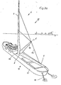
- the ship's hull 15 is anchored on the water by means of anchor chains 17 and can thereby rotate in such a way that the rotor 1 is always in the . Wind flow direction is aligned. It is also possible to fasten the ship's hull 15 to a dolphin washed into the sea floor by means of holding ropes.
- the anchor chains 17 or tether cables can be attached asymmetrically to the ship's hull 15 to compensate for one-sided moments. If, when arranging a rotor 1, 2 on a ship's hull 15, as in the case of wind turbines 33, 34, water flows such as, for example, tidal flows are to be compensated, it is expedient to use the dolphins, piles 57 or the like to attach attached tethers or chains 56 at the center of the lateral point of the ship, that is to say approximately in the middle of the ship, on the underside of the ship, for example on the keel (FIG. 3c).
- the attachment stop 55 of the tethers or chains 56 on the ship's hull 15 can be displaced to starboard or port from the longitudinal axis 59 of the ship's hull 15 (FIG. 3d).
- the water flow presses against bow and stern with approximately the same force.
- the hull 15 thus rotates only about the dolphin or pile 57, but not about itself. If the center of gravity for the rotor 1, 2 lies approximately in the center of the hub 8, the wind can move the hull 15 independently of its movement around the Turn dolphins or stake 57 around themselves in the wind.
- a sail area at the stern of the hull 15, such as a mizzen mast with sail can also be provided.
- FIG. 4a A further embodiment of a wind power plant 30 as an offshore wind power plant is shown in FIG. 4a.
- a rotor 1 with a pylon 19 is arranged on a pontoon 16 in the form of a wind turbine 33.
- the pontoon 16 is also anchored by means of anchor chains 17 so that the rotor 1 can always turn in the direction of the wind flow.
- the support piece 11 it is also possible to design the support piece 11 to be rotatable by means of an actuating device, so that the rotor 1 is rotated into the respective wind inflow direction when the pontoon 16 is stationary.
- the pontoon 16 can be rectangular as well as circular or polygonal. It is also possible to provide the pontoon 16 with lateral arms, so as to increase the stability of the pontoon 16.
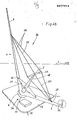
- the rotor 1 is provided with further stiffening means.
- the rotor 1 is on a pontoon 16, which like can be formed in the wind turbine 35.
- the working wings 3 are connected by means of rigid connecting elements 21 which are fastened to the pylon 19.
- the connecting elements 21 are fastened to the working wings 3 by means of bearings 23.
- a cross member 25 is arranged on the upper end section of the pylon 19 and is oriented parallel to the direction of movement of the working wings 3 Counteracts gravity of the working wing 3. Between the end portions of the cross member 25 and the working wings 3, wire ropes 26 or the like are. curious; excited.
- bearings 22 are provided on the working wings 3 in the region of their longitudinal centers of gravity, to which the wire cables 26 can be fastened. It is possible to attach the wire ropes 26 and the connecting elements 21 to the working wings 3 in such a way that they can be adapted to the wind and centrifugal forces by a variable angle of attack by torsion.
- Actuating elements can be used to actuate the wire cables 26 and the connecting elements 21. These can be used as passive control elements such as springs or the like. or can be designed as active control elements such as hydraulic cylinders, motor drives or also as positive controls connected to the pylon 19, for example via eccentrics. This allows the blades 3, 4 to be adjusted cyclically to adapt to the respective operating conditions.
- a secondary rotor 32 which can be connected to an energy generating device, is arranged on the free end section of the one working wing 3. In special cases, it is conceivable that the generation of electrical energy takes place via such secondary rotors 32. However, it is also possible to use such a secondary rotor 32 as a starting aid for the rotor 1. By arranging a secondary rotor 32 appropriately on one of the working wings 3, it is possible to form a circle form flow vortex, which increases the efficiency of the other working wing 3. As a result of the improved flow against the other working wing 3, advantages are achieved with regard to the energy consumption at the wing foot 9, 10, particularly in the case of large spans.
- FIG. 5a shows a possible design of a working wing 3 or supporting wing 4.
- This wing consists of a spar 37, the inside cavity 40 of which can be walked on.
- the cavity 40 serves for receiving control elements and the like.
- frames 38 are fastened at a distance from one another and are provided with a sheeting 39.
- the entire wing is divided into different wing sections 27, which are connected to one another by means of joints 28.
- the individual wing sections 27 can each be rotated relative to one another about these joints 28, so that different angles of attack of the wing sections 37 can be set in sections via the extension of the wing. This makes it possible to optimally adapt each wing to the respective inflow conditions.
- FIG. 5b A further embodiment of a working wing 3 or supporting wing 4 is shown in cross section in FIG. 5b.
- the wing core is formed by a three-belt carrier 41.
- This consists of an upper flange 42, lower flange 43 and rear flange 44.
- the rear flange 44 is located in the area of the trailing edge of the wing.
- Upper chord 42 and lower chord 43 are connected by struts 47.
- Struts 46 are arranged between the upper chord 42 or the lower chord 43 and the rear chord 44.
- the struts 46, 47 can be designed in a grid-like manner in order to increase the torsional rigidity.
- the three-belt carrier 41 is on the outside with a paneling 39 made of wood, sheet metal or the like. surround. However, a covering can also be provided in a manner known per se.
- this can also be provided with special buoyancy aids. It is also possible to form the working wing 3 from two individual wings 29, 30, which can be arranged parallel to one another one behind the other, or one above the other or also at an angle to one another. If the individual wings 29, 30 are arranged one above the other, it is expedient to connect the individual wings 29, 30 by means of profiled connecting elements 31 (FIG. 6cl.
- a wing of the rotor 1, 2 designed like a lattice mast is shown. It consists of four individual wings 29, 29a, 30, 30a, which are connected to one another by means of vertical connecting elements 31 and horizontal connecting elements 48.
- the connecting elements 31, 48 - are preferably profiled and arranged like a lattice mast, so that great inherent rigidity of the wing formed from the four individual wings 29, 29a, 30, 30a is ensured.
- connections both within the wings 3, 4 and the connecting elements 31, 48 of the grid arrangement can be made by welding, screwing, riveting or gluing. It is also possible to connect tubular belts and cross struts by means of pipe sleeves through shrink connections. This means that high-strength spring steels that cannot be welded can also be used.
- the wing weights can be used to compensate for the wind bending moments, for example in the case of a two-wing aircraft such as the rotor 2, the wing weight is selected to be approximately half of the maximum wind torque to be expected. In the case of a single-wing aircraft such as rotor 1, the wing weight is selected as approximately 1/4 of the expected wind moment.
- the support wing 4 is made unbalanced, ie, a centrifugal force is developed at full load, which is greater than that of the work wing 3. As a guideline, the centrifugal force should be about 1/4 of the expected maximum wind moment.
- power generators that are not tied to a fixed speed, such as, for example, rotor-fed asynchronous machines.
- main bearing 24 of the hub 8 it is also possible to design the main bearing 24 of the hub 8 in such a way that electrical energy can be drawn off directly in the region of the main bearing 24.
- appropriately trained electrical generator can be integrated or a magnetic system comparable to a linear motor system is used.
- the generator can be operated in parallel with an external drive device such as be connected to a gas turbine to ensure the continued generation of energy when there is no wind.
- an external drive device such as be connected to a gas turbine to ensure the continued generation of energy when there is no wind.
- the energy contained in the exhaust gases can additionally be used to generate electrical energy by means of the rotor 1, 2.
- rotors 1, 2 it is also possible to directly rotate rotors 1, 2 according to the invention with work tools such as To connect screw conveyors.
- the profile of the blades of the rotor 1, 2 is formed symmetrically in order to be independent of the wind flow direction.
- the speed of the rotor 1, 2 can also be transmitted in the area of the hub via a gearbox or directly to a drive shaft: has a screw intended for marine propulsion.
- the rotor 1, 2 is therefore also used to drive e.g. Sports boats or toy ships are suitable to let them go against the wind.
- rotors 1, 2 when operating pumped storage plants.
- a generator and a water pump are connected to each rotor 1, 2 in parallel to one another.
- water turbines are connected to the generators parallel to the rotors 1, 2.
- the rotors 1, 2 thus serve both to drive the water pumps and the generators, which can take place simultaneously or alternately.
- electrical energy can then be generated by the generators using the water turbines.
Abstract
Die Erfindung betrifft eine Windkraftanlage mit mindestens einem um eine Drehachse drehbaren Flügel. Die Drehachse 5 des Rotors 1 ist schiefwinklig aufgerichtet zur Horizontalen 7 angeordnet, während die Nabe 8 zur Aufnahme des Flügelfußes 9 mit zugehörigen Energieübertragungsmitteln mit einem Auflagerstück 12 verbunden ist. Vorzugsweise wird die Drehachse 5 zur Horizontalen in einem Winkel a von ca. 45° bis 55° angeordnet. Jeder Flügel 3 des Rotors 1 ist in einem Winkel β von ca. 45° bis ca 55° zur Drehachse 5 ausgerichtet. Der Rotor kann aus einem Arbeitsflügel 3 und einem Stützflügel mit Gegengewicht bestehen (Fig. 1).
Description
Es sind bereits verschiedene Ausgestaltungen von Windkraftanlagen bekannt geworden, deren wesentliches Unterscheidungsmerkmal in der Anordnung der Drehachse besteht.Various configurations of wind turbines have already become known, the main distinguishing feature of which is the arrangement of the axis of rotation.
Bei Windkraftanlagen mit horizontalen Drehachsen sind -insbesondere bei Großanlagen- aufgrund der Lasten des Turms, der Gondel, Nabe, Getriebe und Generator aufnimmt, aufwendige bauliche Maßnahmen erforderlich, so daß derartige Windkraftanlagen, bezogenauf die Energieausbeute, einen hohen Investitionsaufwand erfordern. Windkraftanlagen mit vertikaler Drehachse nach dem Darrieus-Prinzip -bei dem die Auftriebskräfte der Blattprofile zur Umwandlung der kinetischen Energie in Rotationsenergie genutzt werden- haben lediglich bei kleineren Leistungen gegenüber Rotoren mit horizontaler Drehachse Anwendungsvorteile. Sie benötigen jedoch besondere Anlaufhilfen, wie z.B. einen Elektromotor oder aber einen Savonius-Rotor. Konstruktionsbedingt ist aber bei Vertikalläufern der auf die Flügellänge bezogene Windeinfangquerschnitt und der Wirkungsgrad geringer als bei Horizontalläufern. Um eine Leistung wie beim Horizontalläufer zu erzielen, bewirken Vertikalläufer eine größere Bauweise und damit erhöhte Kosten.In wind turbines with horizontal axes of rotation - especially in large systems - due to the loads of the tower, the nacelle, hub, gearbox and generator, complex structural measures are required, so that such wind turbines, based on the energy yield, require a high investment. Wind turbines with a vertical axis of rotation according to the Darrieus principle - in which the buoyancy forces of the blade profiles are used to convert the kinetic energy into rotational energy - have application advantages only with smaller outputs compared to rotors with a horizontal axis of rotation. However, you need special start-up aids, such as an electric motor or a Savonius rotor. Due to the design, the wind trap cross-section related to the wing length and the efficiency are lower for vertical rotors than for horizontal rotors. In order to achieve a performance similar to that of the horizontal rotor, vertical rotors result in a larger construction and thus increased costs.
Die Aufgabe der Erfindung besteht darin, eine Windkraftanlage mit mindestens einem um eine Drehachse drehbaren Flügel so auszubilden, daß die Nachteile der bekannten Horizontal- und Vertikalläufer hinsichtlich des Investitionsaufwandes und der Leistungsfähigkeit vermieden werden. Die Windkraftanlage soll zuverlässig im Betrieb, langlebig und wartungsfrei sein und bei einem hohen Wirkungsgrad einen einfachen und unkomplizierten Aufbau haben.The object of the invention is to design a wind turbine with at least one wing rotatable about an axis of rotation in such a way that the disadvantages of the known horizontal and vertical rotors with regard to the investment and the performance are avoided. The wind turbine should be reliable in operation, long-lasting and maintenance-free and, with a high degree of efficiency, simple and uncomplicated to set up.
Erfindungsgemäß erfolgt die Lösung der Aufgabe dadurch, daß die Drehachse des Rotors schiefwinklig aufgerichtet zur Horizontalen angeordnet und die Nabe zur Aufnahme des Flügelfußes mit zugehörigen Energieübertragungsmitteln mit einem Auflagerstück verbunden ist. Bei dieser Lösung befinden sich sämtliche schweren maschinentechnischen Elemente, wie Getriebe, Naben und Generator auf dem Boden und erfordern keine Hochbaumaßnahmen. Da sowohl der Stützflügel wie auch die Arbeitsflügel umlaufend eine Horizontalposition einnehmen können, ist die Montage, Inspektion und Reparatur erheblich erleichtert. Darüberhinaus kann ein Flügel des Rotors zur Sturmsicherheit in dieser Position arretiert werden.According to the invention the object is achieved in that the axis of rotation of the rotor is arranged at an oblique angle to the horizontal and the hub for receiving the wing base with associated energy transmission means with a bearing is connected. With this solution, all heavy mechanical elements, such as gears, hubs and generators, are on the floor and do not require any construction work. Since both the supporting wing and the working wing can assume a horizontal position all round, assembly, inspection and repair are made considerably easier. In addition, a wing of the rotor can be locked in this position for storm safety.
Weitere Merkmale der Erfindung werden in den Unteransprüchen beschrieben. In den Zeichnungen sind Ausführungsbeispiele der Erfindung dargestellt, die nachstehend näher erläutert werden. Es zeigt
- Fig. 1 den Rotor einer erfindungsgemäßen Windkraftanlage in einer schematischen Seitenansicht,
- Fig. 2 eine weitere Ausbildung eines Rotors in einer schematischen Seitenansicht,
- Fig. 3a eine Ausbildung einer schwimmenden Windkraftanlage in einer schematischen Ansicht,
- Fig. 3b eine weitere Ausbildung einer schwimmenden Windkraftanlage in einer Seitenansicht,
- Fig. 4a als Offshorewindkraftwerk ausgebildete Wind-und 4b kraftanlage in schaubildlichen Ansichten,
- Fig. 5a eine Ausbildung eines Flügels eines Rotors für eine Windkraftanlage in einer Explosionsdarstellung,
- Fig. 5b eine andere Ausbildung eines Flügels in einer Seitenansicht im Schnitt,
- Fig. 6a Ausbildungen von Flügeln in verschiedenen
- bis 6b Ansichten,
- Fig. 7 eine Ausbildung der Nabe des Rotors in einer schematischen Seitenansicht.
- 1 shows the rotor of a wind turbine according to the invention in a schematic side view,
- 2 shows a further embodiment of a rotor in a schematic side view,
- 3a shows a design of a floating wind turbine in a schematic view,
- 3b shows a further embodiment of a floating wind turbine in a side view,
- 4a designed as an offshore wind power plant and 4b power plant in diagrammatic views,
- 5a an embodiment of a wing of a rotor for a wind turbine in an exploded view,
- 5b shows another design of a wing in a side view in section,
- Fig. 6a training of wings in different
- up to 6b views,
- Fig. 7 shows an embodiment of the hub of the rotor in a schematic side view.
In den Fig. 1 und 2 sind zwei Rotoren 1, 2 dargestellt, deren Drehachse 5 aufgerichtet schiefwinklig zur Horizontalen 7 angeordnet sind. Jeder Rotor 1, 2 weist eine Nabe 8 auf, die drehbar mit einem Auflagerstück 11 verbunden ist. Das Auflagerstück 11 ist auf einer angedeuteten Grundplatte 12 angeordnet. Der Rotor 1 besteht aus zwei Arbeitsflügeln 3, deren Flügelfüße 9 mit der Nabe 8 verbunden sind. Der Rotor 2 weist demgegenüber nur einen Arbeitsflügel 3 auf, dem ein Stützflügel 4 zugeordnet ist. Auch der Flügelfuß 10 des Stützflügels 4 ist mit der Nabe 8 verbunden. An dem freien Endabschnitt des Stützflügels 4 ist ein Gegengewicht 6 angeordnet. Die Drehachse 5 der Rotoren 1, 2 sind zur Horizontalen 7 in einem WinkelöZ. von etwa 45° angeordnet. Der Winkelß zwischen der Drehachse 5 und dem Arbeitsflügel 3 bzw. Stützflügel 4 beträgt ebenfalls etwa 45°.1 and 2, two
Die Auflagerfläche 11 kann an einem turmartigen Gestell befestigt werden, so daß sich die Rotoren 1, 2 im Abstand vom Boden befinden. Es ist aber auch möglich, die Auflagerstücke an einer Grundplatte 12 zu befestigen, die annähernd auf Nullniveau 13 angeordnet ist. Hierbei kann die Grundplatte 12 bzw. das Auflagerstück 11 mit einer Stelleinrichtung verbunden werden, die es ermöglicht, den Rotor 1, 2 horizontal in verschiedene Richtungen zu drehen. Es ist auch möglich, den Rotor 1, 2 mit einer vom Wind betätigbaren Leiteinrichtung zu versehen, die es ermöglicht, daß sich der Rotor 1, 2 stets in Windanströmrichtung dreht.The
Es ist auch möglich, die Grundplatte 12 mit dem Auflagerstück 11 auf einem Schwimmkörper 18 anzuordnen. Hierdurch kann ein Offshore-Windkraftwerk ausgebildet werden.It is also possible to arrange the
In den Fig. 3a und 3b sind zwei Windkraftanlagen 33, 34 dargestellt, bei denen jeweils ein Rotor 1, 2 auf einem Schiffsrumpf 15 angeordnet ist.3a and 3b, two
Die Windkraftanlage 33 besteht aus einem Rotor 1 mit zwei Arbeitsflügeln 3, die mittels Spannseilen 14 mit einem koaxial zur Drehachse 5 auf der Nabe 8 angeordneten Pylon 19 verbunden sind. Das Hauptlager 24 befindet sich im Bereich der Nabe 8. Die Nabe 8 kann z.B. wie in Fig. 7 dargestellt ausgebildet sein. Hierbei sind die Flügelfüße 9, 10 und der Pylon 19 in einem Ring 49 vereinigt. Der Ring 49 kann zum Abbremsen oder Feststellen des Rotors 1, 2 dienen. Es ist auch möglich, den Ring 49 um feststehende Räder 58 rotieren zu lassen oder magnetisch in der Schwebe zu halten. Der Ring 49 kann auch als Riemenscheibe zur Kraftübertragung verwendet werden. Wenn hierbei der Ubertragungsriemen 50 um 90° verschränkt wird, kann die Abtriebswelle 51 horizontal angeordnet sein. Der Ring 49 kann mit einem Kegelstumpf 52 verbunden sein, der drehbar mit seinem freien Endabschnitt 53 in einem Zapfenlager 54 gelagert ist. Die Windkraftanlage 34 weist einen Rotor 2 mit einem Arbeitsflügel 3 und einem Stützflügel 4 auf. Der Arbeitsflügel 3 und der Stützflügel 4 sind mittels Spannseilen 14, 20 mit einem Pylon 19 verbunden, der ebenfalls koaxial zur Drehachse 5 auf der Nabe 8 angeordnet ist.The
Der Schiffsrumpf 15 ist mittels Ankerketten 17 auf dem Gewässer verankert und kann hierdurch jeweils so drehen, daß der Rotor 1 stets in die.Windanströmrichtung ausgerichtet ist. Es ist auch möglich, den Schiffsrumpf 15 mittels Halteseilen an einem in den Meeresboden eingespülten Dalben zu befestigen.The ship's
Bei ungünstigen Strömungsverhältnissen können die Ankerketten 17 oder Halteseile zur Kompensation von einseitigen Momenten unsymmetrisch am Schiffsrumpf 15 befestigt werden. Wenn bei Anordnung eines Rotors 1, 2 auf einem Schiffsrumpf 15 wie bei den Windkraftanlagen 33, 34 Was- .serströmungen wie z.B. Tideströmungen ausgeglichen werden sollen, ist es zweckmäßig, die an Dalben, Pfählen 57 od.dgl. angeschlagenen Halteseile oder Ketten 56 an der Mitte des Schiffslateralpunktes, also etwa in Schiffsmitte, an der Schiffsunterseite z.B. am Kiel zu befestigen (Fig. 3c). Um Drehmomentenkräfte des Rotors 1, 2 zusätzlich aufzufangen, kann der Befestigungsanschlag 55 der Halteseile oder Ketten 56 am Schiffsrumpf 15 nach Steuerbord oder Backbord aus der Längsachse 59 des Schiffsrumpfs 15 versetzt sein (Fig. 3d). Die Wasserströmung drückt hierbei mit etwa gleicher Kraft gegen Bug und Heck. Der Schiffsrumpf 15 dreht sich dadurch nur um den Dalben oder Pfahl 57, aber nicht um sich selbst. Wenn der Windangriffsschwerpunkt für den Rotor 1, 2 etwa in der Mitte der Nabe 8 liegt, kann der Wind den Schiffsrumpf 15 unabhängig von dessen Bewegung um den Dalben oder Pfahl 57 um sich selbst in den Wind drehen. Zur weiteren Stabilisierung kann auch noch eine Segelfläche am Heck des Schiffsrumpfes 15, wie z.B. ein Besanmast mit Segel vorgesehen werden.If the flow conditions are unfavorable, the
Eine weitere Ausbildung einer Windkraftanlage 30 als Offshorewindkraftwerk ist in Fig. 4a dargestellt. Hier ist ein Rotor 1 mit einem Pylon 19 in der Ausbildung wie bei der Windkraftanlage 33 auf einem Ponton 16 angeordnet. Der Ponton 16 ist ebenfalls mittels Ankerketten 17 so verankert, daß sich der Rotor 1 stets in die Windanströmrichtung eindrehen kann. Es ist aber auch möglich, das Auflagerstück 11 mittels einer Stelleinrichtung drehbar auszubilden, so daß bei feststehendem Ponton 16 der Rotor 1 in die jeweilige Windanströmrichtung eingedreht wird. Der Ponton 16 kann sowohl rechteckförmig wie auch kreisrund oder aber polygonal ausgebildet sein. Es ist auch möglich, den Ponton 16 mit seitlichen Auslegern zu versehen, um so die Stabilität des Pontons 16 zu erhöhen.A further embodiment of a
Bei der in Fig. 4b dargestellten Windkraftanlage 36 ist der Rotor 1 mit weiteren Versteifungsmitteln versehen. Der Rotor 1 befindet sich auf einem Ponton 16, der wie bei der Windkraftanlage 35 ausgebildet sein kann. Die Arbeitsflügel 3 sind mittels starrer Verbindungselemente 21 verbunden, die an dem Pylon 19 befestigt sind. Um eine Drehbarkeit der Arbeitsflügel 3 um ihre Längsachse zu ermöglichen, erfolgt die Befestigung der Verbindungselemente 21 an den Arbeitsflügeln 3 mittels Lagern 23. An dem oberen Endabschnitt des Pylons 19 ist ein Querträger 25 angeordnet, der parallel zur Bewegungsrichtung der Arbeitsflügel 3 ausgerichtet ist und der Schwerkraft der Arbeitsflügel 3 entgegenwirkt. Zwischen den Endabschnitten des Querträgers 25 und den Arbeitsflügeln 3 sind Drahtseile 26 od.dgl. gespannt. Hierzu sind an den Arbeitsflügeln 3 im Bereich von deren Längsschwerpunkten Lager 22 vorgesehen, an denen die Drahtseile 26 befestigt werden können. Es ist möglich, die Drahtseile 26 und die Verbindungselemente 21 so an den Arbeitsflügeln 3 zu befestigen, daß diese durch Torsion den Windkräften und Zentrifugalkräften durch ei- .nen variablen Anstellwinkel angepaßt werden können. Zur Betätigung der Drahtseile 26 und der Verbindungselemente 21 können nicht näher dargestellte Stellelemente verwendet werden. Diese können entweder als passive Stellelemente wie Federn od.dgl. oder aber als aktive Stellelemente wie Hydraulikzylinder, motorische Antriebe oder aber auch als mit dem Pylon 19 z.B. über Exzenter verbundene Zwangssteuerungen ausgebildet sein. Dadurch können die Flügel 3, 4 zur Anpassung an die jeweiligen Betriebsbedingungen zyklisch verstellt werden.In the
An dem freien Endabschnitt des einen Arbeitsflügels 3 ist ein Sekundärrotor 32 angeordnet, der mit einer Energieerzeugungseinrichtung verbunden sein kann. Es ist in besonderen Fällen denkbar, daß über derartige Sekundärrotoren 32 die Erzeugung elektrischer Energie erfolgt. Es ist aber auch möglich, einen solchen Sekundärrotor 32 als Anfahrhilfe für den Rotor 1 zu verwenden. Durch eine entsprechende Anordnung eines Sekundärrotors 32 an einem der Arbeitsflügel 3 ist es möglich, einen kreisförmigen Strömungswirbel auszubilden, der den Wirkungsgrad des anderen Arbeitsflügels 3 erhöht. Durch die verbesserte Anströmung des anderen Arbeitsflügels 3 werden im Hinblick auf die Energieabnahme am Flügelfuß 9, 10 insbesondere bei großen Spannweiten Vorteile erzielt.A
In Fig. 5a ist eine mögliche Ausbildung eines Arbeitsflügels 3 oder Stützflügels 4 dargestellt. Dieser Flügel besteht aus-.einem Holm 37, dessen innenseitiger Hohlraum 40 begehbar sein kann. Der Hohlraum 40 dient zur Aufnahme von Steuerelementen u.dgl. An dem Holm 37 sind im Abstand voneinander Spanten 38 befestigt, die mit einer Beplankung 39 versehen werden. Der gesamte Flügel ist in verschiedene Flügelabschnitte 27 unterteilt, die mittels Gelenken 28 miteinander verbunden sind, Um diese Gelenke 28 sind die einzelnen Flügelabschnitte 27 jeweils relativ zueinander verdrehbar, so daß über die Streckung des Flügels abschnittsweise unterschiedliche Anstellwinkel der Flügelabschnitte 37 eingestellt werden können. Hierdurch ist es möglich, jeden Flügel an die jeweiligen Anströmverhältnisse optimal anzupassen.5a shows a possible design of a working
In Fig. 5b ist eine weitere Ausbildung eines Arbeitsflügels 3 oder Stützflügels 4 im Querschnitt dargestellt. Der Flügelkern wird durch einen Dreigurtträger 41 ausgebildet. Dieser besteht aus einem Obergurt 42, Untergurt 43 und Hintergurt 44. Der Hintergurt 44 befindet sich im Bereich der Flügelhinterkante. Obergurt 42 und Untergurt 43 sind durch Verstrebungen 47 verbunden. Zwischen dem Obergurt 42 bzw. dem Untergurt 43 und dem Hintergurt 44 sind Verstrebungen 46 angeordnet. Die Verstrebungen 46, 47 können gitterartig ausgebildet sein, um die Verwindungssteifigkeit zu erhöhen. Der Dreigurtträger 41 ist außenseitig mit einer Beplankung 39 aus Holz, Metallblech od.dgl. umgeben. Es kann aber auch in an sich bekannter Weise eine Bespannung vorgesehen werden.A further embodiment of a working
Um den Wirkungsgrad eines Arbeitsflügels 3 zu erhöhen, kann.dieser auch mit besonderen Auftriebshilfen versehen sein. Es ist auch möglich, den Arbeitsflügel 3 aus zwei Einzelflügeln 29, 30 auszubilden, die parallel zueinander hintereinander oder aber übereinander oder aber auch zueinander schräg versetzt angeordnet sein können. Bei einer Anordnung der Einzelflügel 29, 30 übereinander ist es zweckmäßig, die Einzelflügel 29, 30 mittels profilierter Verbindungselemente 31 zu verbinden (Fig. 6cl.In order to increase the efficiency of a working
In Fig. 6a und 6b ist ein gittermastartig ausgebildeter Flügel des Rotors 1, 2 dargestellt. Er besteht aus vier Einzelflügeln 29, 29a, 30, 30a, die mittels vertikaler Verbindungselemente 31 und horizontaler Verbindungselemente 48 miteinander verbunden sind. Die Verbindungselemente 31, 48-sind vorzugsweise profiliert und gittermastartig angeordnet, so daß eine große Eigensteifigkeit des aus den vier Einzelflügeln 29, 29a, 30, 30a gebildeten Flügels gewährleistet ist.6a and 6b, a wing of the
Die Verbindungen sowohl innerhalb der Flügel 3, 4 wie auch der Verbindungselemente 31, 48 der Gitteranordnung können durch Schweißen, Schrauben, Nieten oder Kleben erfolgen. Es ist auch möglich, röhrenförmige Gurte und Querverstrebungen mittels Rohrmuffen durch Schrumpfverbindungen zu verbinden, Hierdurch lassen sich auch hochfeste Federstähle verwenden, die nicht schweißbar sind.The connections both within the
Die Flügelgewichte können zur Kompensation der Windbiegemomente herangezogen werden, indem z.B. bei einem Zweiflügler wie dem Rotor 2 das Flügelgewicht etwa zur Hälfte des zu erwartenden maximalen Windmomentes gewählt wird. Bei einem Einflügler wie beim Rotor 1 wird das Flügelgewicht als etwa 1/4 des zu erwartenden Windmomentes gewählt. Beim Rotor 1 wird der Stützflügel 4 unwuchtig gemacht, d.h., bei Vollast eine Zentrifugalkraft entwickelt, die größer ist, als die des Arbeitsflügels 3. Als Richtwert soll die Zentrifugalkraft um etwa 1/4 des zu erwartenden maximalen Windmomentes größer sein. Zur Stromerzeugung werden zweckmäßigerweise Stromerzeuger verwendet, die nicht an eine feste Drehzahl gebunden sind, wie z.B. läufergespeiste Asynchronmaschinen. Es ist auch möglich, das Hauptlager 24 der Nabe 8 so auszubilden, daß im Bereich des Hauptlagers 24 unmittelbar elektrische Energie abgenommen werden kann. Hierzu kann in das Hauptlager 24 entweder ein . entsprechend ausgebildeter elektrischer Generator integriert werden oder aber es findet ein Magnetsystem vergleichbar einem Linearmotorsystem Anwendung.The wing weights can be used to compensate for the wind bending moments, for example in the case of a two-wing aircraft such as the
Der Generator kann parallel mit einer externen Antriebseinrichtung wie z.B. einer Gasturbine verbunden sein, um bei Windstille die weitere Energieerzeugung zu gewährleisten. Hierbei ist es möglich, die Abgase der Gasturbine über entsprechende Rohrleitungen zu einem an .den Flügeln des Rotors 1, 2 ausgebildeten Düsensystem zu leiten, die beim Austritt der Abgase in die Atmosphäre den Rotor 1, 2 in eine Drehbewegung versetzen. Hierdurch kann die in den Abgasen enthaltene Energie zusätzlich zur Erzeugung elektrischer Energie mittels des Rotors 1, 2 verwendet werden.The generator can be operated in parallel with an external drive device such as be connected to a gas turbine to ensure the continued generation of energy when there is no wind. Here, it is possible to conduct the exhaust gases of the gas turbine via appropriate pipelines to a nozzle system formed on the blades of the
Es ist auch möglich, Rotoren 1, 2 entsprechend der Erfindung unmittelbar mit Arbeitsgeräten wie z.B. Schnekkenförderern zu verbinden. In diesem Fall wird das Profil der Flügel des Rotors 1, 2 symmetrisch ausgebildet, um von der Windanströmrichtung unabhängig zu sein. Darüberhinaus kann auch im Bereich der Nabe die Drehzahl des Rotors 1, 2 über ein Getriebe oder aber direkt auf eine Antriebswelle:übertragen werden, die z.B. eine für einen Schiffsantrieb bestimmte Schraube aufweist. Der Rotor 1, 2 ist daher auch zum Antrieb von z.B. Sportbooten oder Spielzeugschiffen geeignet, um diese gegen den Wind fahren lassen zu können.It is also possible to directly rotate
Es besteht auch die Möglichkeit, Rotoren 1, 2 beim Betrieb von Pumpspeicherwerken zu nutzen. In diesem Fall ist an jedem Rotor 1, 2 parallel zueinander ein Generator und eine Wasserpumpe angeschlossen. Gleichzeitig sind Wasserturbinen parallel zu den Rotoren 1, 2 mit den Generatoren verbunden. Die Rotoren 1, 2 dienen somit sowohl zum Antrieb der Wasserpumpen wie auch der Generatoren, was gleichzeitig oder wechselweise erfolgen kann. Bei gefülltem Pumpspeicherwerk kann dann mittels der Wasserturbinen über die Generatoren elektrische Energie erzeugt werden.There is also the possibility of using
Claims (50)
Priority Applications (1)
| Application Number | Priority Date | Filing Date | Title |
|---|---|---|---|
| AT82108589T ATE25420T1 (en) | 1981-10-26 | 1982-09-17 | WIND POWER PLANT WITH AT LEAST ONE BLADE ROTATIVE ABOUT ONE ROTARY AXIS. |
Applications Claiming Priority (4)
| Application Number | Priority Date | Filing Date | Title |
|---|---|---|---|
| DE3142434 | 1981-10-26 | ||
| DE3142434 | 1981-10-26 | ||
| DE3213396 | 1982-04-10 | ||
| DE3213396 | 1982-04-10 |
Publications (2)
| Publication Number | Publication Date |
|---|---|
| EP0077914A1 true EP0077914A1 (en) | 1983-05-04 |
| EP0077914B1 EP0077914B1 (en) | 1987-02-04 |
Family
ID=25796884
Family Applications (1)
| Application Number | Title | Priority Date | Filing Date |
|---|---|---|---|
| EP82108589A Expired EP0077914B1 (en) | 1981-10-26 | 1982-09-17 | Wind power plant with at least one rotating blade |
Country Status (23)
| Country | Link |
|---|---|
| US (1) | US4624623A (en) |
| EP (1) | EP0077914B1 (en) |
| JP (1) | JPS58501780A (en) |
| KR (1) | KR840002073A (en) |
| AR (1) | AR228532A1 (en) |
| AT (1) | ATE25420T1 (en) |
| AU (1) | AU563109B2 (en) |
| BR (1) | BR8207944A (en) |
| CA (1) | CA1212333A (en) |
| DE (1) | DE3234170C2 (en) |
| DK (1) | DK292483A (en) |
| ES (1) | ES516816A0 (en) |
| FI (1) | FI832125A0 (en) |
| GR (1) | GR78396B (en) |
| HU (1) | HUT42600A (en) |
| IL (1) | IL66973A (en) |
| MX (1) | MX154409A (en) |
| NO (1) | NO832289L (en) |
| PL (1) | PL138707B1 (en) |
| PT (1) | PT75732B (en) |
| RO (1) | RO88449A (en) |
| SU (1) | SU1301323A3 (en) |
| WO (1) | WO1983001489A1 (en) |
Cited By (1)
| Publication number | Priority date | Publication date | Assignee | Title |
|---|---|---|---|---|
| EP0193624A1 (en) * | 1983-09-12 | 1986-09-10 | Oeko-Energie Ag | Wind power propulsion |
Families Citing this family (32)
| Publication number | Priority date | Publication date | Assignee | Title |
|---|---|---|---|---|
| EP0364020B1 (en) * | 1988-10-03 | 1992-12-30 | Josef Moser | Rotor for a wind motor |
| US5186822A (en) * | 1991-02-25 | 1993-02-16 | Ocean Resources Engineering, Inc. | Wave powered desalination apparatus with turbine-driven pressurization |
| EP1310671A4 (en) * | 2000-08-17 | 2005-06-01 | Hongsun Hua | Windmill |
| US8197179B2 (en) * | 2001-06-14 | 2012-06-12 | Douglas Spriggs Selsam | Stationary co-axial multi-rotor wind turbine supported by continuous central driveshaft |
| WO2006043932A1 (en) * | 2004-10-14 | 2006-04-27 | Lee Tommy L | Wind powered generator platform |
| CN100443718C (en) * | 2006-05-25 | 2008-12-17 | 刘运超 | Oblique axis type windpower generating unit |
| US7802426B2 (en) | 2008-06-09 | 2010-09-28 | Sustainx, Inc. | System and method for rapid isothermal gas expansion and compression for energy storage |
| US8479505B2 (en) | 2008-04-09 | 2013-07-09 | Sustainx, Inc. | Systems and methods for reducing dead volume in compressed-gas energy storage systems |
| US8359856B2 (en) | 2008-04-09 | 2013-01-29 | Sustainx Inc. | Systems and methods for efficient pumping of high-pressure fluids for energy storage and recovery |
| US20110266810A1 (en) | 2009-11-03 | 2011-11-03 | Mcbride Troy O | Systems and methods for compressed-gas energy storage using coupled cylinder assemblies |
| US7958731B2 (en) | 2009-01-20 | 2011-06-14 | Sustainx, Inc. | Systems and methods for combined thermal and compressed gas energy conversion systems |
| US8225606B2 (en) | 2008-04-09 | 2012-07-24 | Sustainx, Inc. | Systems and methods for energy storage and recovery using rapid isothermal gas expansion and compression |
| US8448433B2 (en) | 2008-04-09 | 2013-05-28 | Sustainx, Inc. | Systems and methods for energy storage and recovery using gas expansion and compression |
| US7832207B2 (en) | 2008-04-09 | 2010-11-16 | Sustainx, Inc. | Systems and methods for energy storage and recovery using compressed gas |
| US8037678B2 (en) | 2009-09-11 | 2011-10-18 | Sustainx, Inc. | Energy storage and generation systems and methods using coupled cylinder assemblies |
| US20100307156A1 (en) | 2009-06-04 | 2010-12-09 | Bollinger Benjamin R | Systems and Methods for Improving Drivetrain Efficiency for Compressed Gas Energy Storage and Recovery Systems |
| US8677744B2 (en) | 2008-04-09 | 2014-03-25 | SustaioX, Inc. | Fluid circulation in energy storage and recovery systems |
| US8250863B2 (en) | 2008-04-09 | 2012-08-28 | Sustainx, Inc. | Heat exchange with compressed gas in energy-storage systems |
| US8474255B2 (en) | 2008-04-09 | 2013-07-02 | Sustainx, Inc. | Forming liquid sprays in compressed-gas energy storage systems for effective heat exchange |
| US8240140B2 (en) | 2008-04-09 | 2012-08-14 | Sustainx, Inc. | High-efficiency energy-conversion based on fluid expansion and compression |
| KR101028748B1 (en) * | 2008-08-08 | 2011-04-14 | 이달은 | Wind power generator of large size |
| US7963110B2 (en) | 2009-03-12 | 2011-06-21 | Sustainx, Inc. | Systems and methods for improving drivetrain efficiency for compressed gas energy storage |
| US8104274B2 (en) | 2009-06-04 | 2012-01-31 | Sustainx, Inc. | Increased power in compressed-gas energy storage and recovery |
| US8171728B2 (en) | 2010-04-08 | 2012-05-08 | Sustainx, Inc. | High-efficiency liquid heat exchange in compressed-gas energy storage systems |
| US8191362B2 (en) | 2010-04-08 | 2012-06-05 | Sustainx, Inc. | Systems and methods for reducing dead volume in compressed-gas energy storage systems |
| US8234863B2 (en) | 2010-05-14 | 2012-08-07 | Sustainx, Inc. | Forming liquid sprays in compressed-gas energy storage systems for effective heat exchange |
| US8747070B2 (en) * | 2010-07-13 | 2014-06-10 | Greg E Blonder | Spinning horizontal axis wind turbine |
| US8495872B2 (en) | 2010-08-20 | 2013-07-30 | Sustainx, Inc. | Energy storage and recovery utilizing low-pressure thermal conditioning for heat exchange with high-pressure gas |
| US8578708B2 (en) | 2010-11-30 | 2013-11-12 | Sustainx, Inc. | Fluid-flow control in energy storage and recovery systems |
| WO2012158781A2 (en) | 2011-05-17 | 2012-11-22 | Sustainx, Inc. | Systems and methods for efficient two-phase heat transfer in compressed-air energy storage systems |
| US20130091834A1 (en) | 2011-10-14 | 2013-04-18 | Sustainx, Inc. | Dead-volume management in compressed-gas energy storage and recovery systems |
| DE112020007452A5 (en) * | 2019-07-27 | 2023-06-07 | Siva RaghuRam Prasad Chennupati | UNIVERSAL PROPELLER, OPERATING METHOD AND FAVORITE USES |
Citations (11)
| Publication number | Priority date | Publication date | Assignee | Title |
|---|---|---|---|---|
| FR542172A (en) * | 1921-10-11 | 1922-08-07 | Improvements made to motor devices operating under the action of the wind | |
| DE577917C (en) * | 1927-06-27 | 1933-06-07 | Expl Des Procedes Maurice Lebl | Wind turbine coupled to an electric generator |
| US2627928A (en) * | 1945-04-30 | 1953-02-10 | Alexander S Mullgardt | Propeller |
| DE877280C (en) * | 1947-02-03 | 1953-05-21 | Richard Bauer | Wind power machine |
| DE907400C (en) * | 1943-12-21 | 1954-03-25 | Richard Bauer | Wind turbine |
| DE2753956B1 (en) * | 1977-12-03 | 1979-03-22 | Maschf Augsburg Nuernberg Ag | Maintenance or inspection facility for large wind turbines |
| DE2806874A1 (en) * | 1976-08-26 | 1979-08-23 | Praktisk Teknik Ab | HORIZONTAL AXIS ROTOR, PREFERABLY FOR WIND POWER PLANTS |
| FR2464384A1 (en) * | 1979-08-28 | 1981-03-06 | Charpentier Pierre | High speed wind generator - uses second wind turbine mounted on tip of primary turbine blade whose rotation forces air through second turbine giving high shaft speed |
| DE2940485A1 (en) * | 1978-02-23 | 1981-04-16 | Sidney Philadelphia Pa. Dvorak | PLANT FOR GENERATING ELECTRICAL ENERGY |
| DE2944718A1 (en) * | 1979-11-06 | 1981-05-21 | Hans-Dietrich Ing.(grad.) 2000 Hamburg Goslich | ROTOR FOR LIGHTWEIGHT WIND TURBINES |
| FR2486018A1 (en) * | 1980-07-03 | 1982-01-08 | Henry Eugene | Wind driven catamaran with submerged propeller - is rotated by vertical shaft supporting variable orientation paddle wheels |
Family Cites Families (24)
| Publication number | Priority date | Publication date | Assignee | Title |
|---|---|---|---|---|
| US869709A (en) * | 1906-09-28 | 1907-10-29 | Josef Homola | Machine for use with wind-power. |
| NL7176C (en) * | 1918-07-17 | |||
| US1883336A (en) * | 1925-02-12 | 1932-10-18 | Chillingworth Rudolph | Screw propeller for aircraft |
| US2152984A (en) * | 1936-08-17 | 1939-04-04 | Wilford Edward Burke | Watercraft |
| FR993473A (en) * | 1949-06-28 | 1951-10-31 | Wind power generating installation | |
| US2661068A (en) * | 1950-09-02 | 1953-12-01 | Leo B Gaskill | Air circulator for orchards and field crops |
| CH356366A (en) * | 1959-12-07 | 1961-08-15 | Marbury Fendall Jr | Method for propelling a ship and installation for implementing this method |
| DE1120390B (en) * | 1961-03-18 | 1961-12-21 | Wilhelm Goldau | Vertical single-wing wind power machine with angled output shaft |
| DE2814247A1 (en) * | 1977-04-05 | 1978-10-19 | Daniel Henggeler | Wind driven electrical generator - utilised magnus effect on two revolving rotors to produce couple driving generator |
| DK140382B (en) * | 1977-07-25 | 1979-08-13 | Peder Ulrik Poulsen | Wind Power. |
| DE2737767C2 (en) * | 1977-08-22 | 1979-05-17 | Ulrich Prof. Dr.-Ing. 7312 Kirchheim Huetter | Wind turbine |
| US4168439A (en) * | 1977-11-28 | 1979-09-18 | Palma F Neto | Wind turbine |
| US4264279A (en) * | 1978-05-12 | 1981-04-28 | Dereng Viggo G | Fixed geometry self starting transverse axis wind turbine |
| SE414073B (en) * | 1978-10-06 | 1980-07-07 | Ljungstrom Olle | WIND TURBINE OF TWO FLOWER TYPE SA CALLED BACK BLADE OR DARRIEV TYPE RESP GYROMILL TYPE WITH FIXED OR PA KNITTED CYLICALLY ADJUSTABLE BLAD ANGLE |
| DE2844262A1 (en) * | 1978-10-11 | 1980-04-17 | Franz Xaver Prof Dr I Wortmann | SINGLE BLADE ROTOR FOR WIND TURBINES |
| JPS5579319A (en) * | 1978-12-07 | 1980-06-14 | Shiyaaman Baaton | Method of introducing vitamine a analogue to respiratory tract of smoker |
| GB2049831A (en) * | 1979-05-29 | 1980-12-31 | Chabek K | Wind Turbine Plant |
| US4355956A (en) * | 1979-12-26 | 1982-10-26 | Leland O. Lane | Wind turbine |
| FR2473639A1 (en) * | 1980-01-16 | 1981-07-17 | Aeropower | AEROGENERATOR WITH AXIS OF ORIENTATION ORDER |
| US4360315A (en) * | 1980-04-14 | 1982-11-23 | Leonard Olson | Vortex wind turbine |
| US4353702A (en) * | 1980-07-21 | 1982-10-12 | F M Machine Company | Sailing craft mainsail and auxiliary propulsion means therefor |
| DE3039387A1 (en) * | 1980-10-18 | 1982-06-03 | Bernhard 6800 Mannheim Jöst | WIND DRIVE FOR VEHICLES AND STATIONARY MACHINES OF ANY KIND |
| US4432695A (en) * | 1981-10-29 | 1984-02-21 | Institut Gidrodinamiki Imeni M.A. Lavrentieva | Wind motor |
| US4533297A (en) * | 1982-09-15 | 1985-08-06 | Bassett David A | Rotor system for horizontal axis wind turbines |
-
1982
- 1982-09-15 DE DE3234170A patent/DE3234170C2/en not_active Expired
- 1982-09-17 HU HU823401A patent/HUT42600A/en unknown
- 1982-09-17 WO PCT/DE1982/000186 patent/WO1983001489A1/en active Application Filing
- 1982-09-17 EP EP82108589A patent/EP0077914B1/en not_active Expired
- 1982-09-17 BR BR8207944A patent/BR8207944A/en unknown
- 1982-09-17 JP JP57502817A patent/JPS58501780A/en active Pending
- 1982-09-17 RO RO11140382A patent/RO88449A/en unknown
- 1982-09-17 AT AT82108589T patent/ATE25420T1/en not_active IP Right Cessation
- 1982-09-17 AU AU89047/82A patent/AU563109B2/en not_active Ceased
- 1982-10-12 IL IL66973A patent/IL66973A/en unknown
- 1982-10-19 GR GR69571A patent/GR78396B/el unknown
- 1982-10-25 ES ES516816A patent/ES516816A0/en active Granted
- 1982-10-25 CA CA000414096A patent/CA1212333A/en not_active Expired
- 1982-10-25 PT PT75732A patent/PT75732B/en unknown
- 1982-10-26 AR AR291096A patent/AR228532A1/en active
- 1982-10-26 KR KR1019820004797A patent/KR840002073A/en unknown
- 1982-10-26 MX MX194941A patent/MX154409A/en unknown
- 1982-10-26 PL PL1982238737A patent/PL138707B1/en unknown
-
1983
- 1983-06-14 FI FI832125A patent/FI832125A0/en not_active Application Discontinuation
- 1983-06-23 NO NO832289A patent/NO832289L/en unknown
- 1983-06-24 DK DK292483A patent/DK292483A/en not_active Application Discontinuation
- 1983-06-24 SU SU833609883A patent/SU1301323A3/en active
-
1985
- 1985-03-20 US US06/714,614 patent/US4624623A/en not_active Expired - Fee Related
Patent Citations (11)
| Publication number | Priority date | Publication date | Assignee | Title |
|---|---|---|---|---|
| FR542172A (en) * | 1921-10-11 | 1922-08-07 | Improvements made to motor devices operating under the action of the wind | |
| DE577917C (en) * | 1927-06-27 | 1933-06-07 | Expl Des Procedes Maurice Lebl | Wind turbine coupled to an electric generator |
| DE907400C (en) * | 1943-12-21 | 1954-03-25 | Richard Bauer | Wind turbine |
| US2627928A (en) * | 1945-04-30 | 1953-02-10 | Alexander S Mullgardt | Propeller |
| DE877280C (en) * | 1947-02-03 | 1953-05-21 | Richard Bauer | Wind power machine |
| DE2806874A1 (en) * | 1976-08-26 | 1979-08-23 | Praktisk Teknik Ab | HORIZONTAL AXIS ROTOR, PREFERABLY FOR WIND POWER PLANTS |
| DE2753956B1 (en) * | 1977-12-03 | 1979-03-22 | Maschf Augsburg Nuernberg Ag | Maintenance or inspection facility for large wind turbines |
| DE2940485A1 (en) * | 1978-02-23 | 1981-04-16 | Sidney Philadelphia Pa. Dvorak | PLANT FOR GENERATING ELECTRICAL ENERGY |
| FR2464384A1 (en) * | 1979-08-28 | 1981-03-06 | Charpentier Pierre | High speed wind generator - uses second wind turbine mounted on tip of primary turbine blade whose rotation forces air through second turbine giving high shaft speed |
| DE2944718A1 (en) * | 1979-11-06 | 1981-05-21 | Hans-Dietrich Ing.(grad.) 2000 Hamburg Goslich | ROTOR FOR LIGHTWEIGHT WIND TURBINES |
| FR2486018A1 (en) * | 1980-07-03 | 1982-01-08 | Henry Eugene | Wind driven catamaran with submerged propeller - is rotated by vertical shaft supporting variable orientation paddle wheels |
Non-Patent Citations (1)
| Title |
|---|
| THE ENGINEER, Band 239, Nr. 6180/81, 22./29. August 1974, Seiten 55-59, Morgan-Grampian Ltd., London, G.B. * |
Cited By (1)
| Publication number | Priority date | Publication date | Assignee | Title |
|---|---|---|---|---|
| EP0193624A1 (en) * | 1983-09-12 | 1986-09-10 | Oeko-Energie Ag | Wind power propulsion |
Also Published As
| Publication number | Publication date |
|---|---|
| DE3234170A1 (en) | 1983-05-11 |
| CA1212333A (en) | 1986-10-07 |
| DK292483D0 (en) | 1983-06-24 |
| EP0077914B1 (en) | 1987-02-04 |
| RO88449A (en) | 1986-01-30 |
| BR8207944A (en) | 1983-09-20 |
| HUT42600A (en) | 1987-07-28 |
| FI832125L (en) | 1983-06-14 |
| WO1983001489A1 (en) | 1983-04-28 |
| PL138707B1 (en) | 1986-10-31 |
| DK292483A (en) | 1983-06-24 |
| KR840002073A (en) | 1984-06-11 |
| FI832125A0 (en) | 1983-06-14 |
| AU563109B2 (en) | 1987-06-25 |
| PT75732B (en) | 1984-12-03 |
| ATE25420T1 (en) | 1987-02-15 |
| JPS58501780A (en) | 1983-10-20 |
| SU1301323A3 (en) | 1987-03-30 |
| NO832289L (en) | 1983-06-23 |
| ES8307340A1 (en) | 1983-06-16 |
| PT75732A (en) | 1982-11-01 |
| US4624623A (en) | 1986-11-25 |
| PL238737A1 (en) | 1983-06-20 |
| AU8904782A (en) | 1983-05-05 |
| DE3234170C2 (en) | 1985-04-11 |
| IL66973A (en) | 1988-06-30 |
| ES516816A0 (en) | 1983-06-16 |
| MX154409A (en) | 1987-08-11 |
| AR228532A1 (en) | 1983-03-15 |
| GR78396B (en) | 1984-09-27 |
Similar Documents
| Publication | Publication Date | Title |
|---|---|---|
| EP0077914B1 (en) | Wind power plant with at least one rotating blade | |
| DE102007013293B3 (en) | Underwater power station i.e. free-standing power station, operating method, involves fastening turbine to joint connection by spacer element, and causing torque for making pivoting movement by driving turbine using machine in motor mode | |
| EP3464882B1 (en) | Floating wind turbine having a plurality of energy conversion units | |
| DE10205988A1 (en) | Wind turbine | |
| WO1982003662A1 (en) | Plant for utilization of wind and waves | |
| DE19744174A1 (en) | Air flow converter for generating electrical energy without harmful substances on ocean | |
| WO2018172545A1 (en) | Floating offshore wind power plant having a vertical rotor and modular wind farm comprising a plurality of such wind power plants | |
| DE102013202566B3 (en) | Wind turbine | |
| US20220213871A1 (en) | Ducted wind turbine and support platform | |
| DE102008057212A1 (en) | Rotor, particularly helicopter rotor or ship rotor for conversion of energy into rotary motion as flow converter for wind turbine or water turbine, comprises annular rotor blade, which has vane profile with vane projection in cross section | |
| DE102008008060B4 (en) | Rotor with a parallel to the axis of rotation flowed annular rotor blade | |
| WO2003103113A2 (en) | Vertical rotor comprising guidable blades | |
| DE19526129A1 (en) | Self-regulating wind power plant | |
| DE2905569A1 (en) | Wind driven turbine with prism shaped rotors - has wind deflecting shield which projects rotors moving against windward direction | |
| EP0193624A1 (en) | Wind power propulsion | |
| US11208982B2 (en) | System for generating electric energy from wind or hydraulic energy | |
| DE102007057077A1 (en) | Rotor for use as e.g. ship rotor, has annular rotor blade, where blade position is changed between two of vertices with maximum distance from uplift position into down position | |
| CN1009569B (en) | Swing wing type vertical windmill | |
| DE102004012712A1 (en) | Structure for converting wind energy into electrical energy comprises sails fixed to continuous cables guided over drive wheels that convert kinetic wind energy into the rotational movement of current generators | |
| DE202010016041U1 (en) | Wind turbine and wind farm | |
| DD205722A5 (en) | WIND TURBINE | |
| DE202021003974U1 (en) | Offshore flow power plant for generating electricity | |
| EP3688304B1 (en) | Oscillating hydrofoils-generator/drive for converting energy | |
| DE102009013161A1 (en) | Hub-airfoil system e.g. video system and camera system, for controlling e.g. wind energy, in wind turbine, has energy convertors and energy storing device arranged under base of base body in closed housing | |
| DE10325342A1 (en) | Rotor for a power turbine has a vertical axle affected by a flowing substance and blades to adjust to direction of flow |
Legal Events
| Date | Code | Title | Description |
|---|---|---|---|
| PUAI | Public reference made under article 153(3) epc to a published international application that has entered the european phase |
Free format text: ORIGINAL CODE: 0009012 |
|
| AK | Designated contracting states |
Designated state(s): AT BE CH FR GB IT LI NL SE |
|
| 17P | Request for examination filed |
Effective date: 19831111 |
|
| D17P | Request for examination filed (deleted) | ||
| R17P | Request for examination filed (corrected) |
Effective date: 19831111 |
|
| GRAA | (expected) grant |
Free format text: ORIGINAL CODE: 0009210 |
|
| AK | Designated contracting states |
Kind code of ref document: B1 Designated state(s): AT BE CH FR GB IT LI NL SE |
|
| REF | Corresponds to: |
Ref document number: 25420 Country of ref document: AT Date of ref document: 19870215 Kind code of ref document: T |
|
| ITF | It: translation for a ep patent filed |
Owner name: ST. TECN. INGG. SIMONI - DE BLASIO |
|
| ET | Fr: translation filed | ||
| PGFP | Annual fee paid to national office [announced via postgrant information from national office to epo] |
Ref country code: NL Payment date: 19870930 Year of fee payment: 6 |
|
| PLBE | No opposition filed within time limit |
Free format text: ORIGINAL CODE: 0009261 |
|
| STAA | Information on the status of an ep patent application or granted ep patent |
Free format text: STATUS: NO OPPOSITION FILED WITHIN TIME LIMIT |
|
| 26N | No opposition filed | ||
| PG25 | Lapsed in a contracting state [announced via postgrant information from national office to epo] |
Ref country code: GB Effective date: 19880917 Ref country code: AT Effective date: 19880917 |
|
| PG25 | Lapsed in a contracting state [announced via postgrant information from national office to epo] |
Ref country code: SE Effective date: 19880918 |
|
| PG25 | Lapsed in a contracting state [announced via postgrant information from national office to epo] |
Ref country code: BE Effective date: 19880930 |
|
| BERE | Be: lapsed |
Owner name: OKO-ENERGIE A.G. Effective date: 19880930 |
|
| PG25 | Lapsed in a contracting state [announced via postgrant information from national office to epo] |
Ref country code: NL Effective date: 19890401 |
|
| NLV4 | Nl: lapsed or anulled due to non-payment of the annual fee | ||
| PG25 | Lapsed in a contracting state [announced via postgrant information from national office to epo] |
Ref country code: FR Free format text: LAPSE BECAUSE OF NON-PAYMENT OF DUE FEES Effective date: 19890531 |
|
| GBPC | Gb: european patent ceased through non-payment of renewal fee | ||
| REG | Reference to a national code |
Ref country code: FR Ref legal event code: ST |
|
| EUG | Se: european patent has lapsed |
Ref document number: 82108589.1 Effective date: 19890614 |
|
| PGFP | Annual fee paid to national office [announced via postgrant information from national office to epo] |
Ref country code: CH Payment date: 20001231 Year of fee payment: 19 |
|
| PG25 | Lapsed in a contracting state [announced via postgrant information from national office to epo] |
Ref country code: LI Free format text: LAPSE BECAUSE OF NON-PAYMENT OF DUE FEES Effective date: 20010930 Ref country code: CH Free format text: LAPSE BECAUSE OF NON-PAYMENT OF DUE FEES Effective date: 20010930 |
|
| REG | Reference to a national code |
Ref country code: CH Ref legal event code: PL |